Week 10 - Challenge 1- Attachment Feature Creation (Ribs & Screw Boss)
A per the challenge, A- Surface was given as shown below.
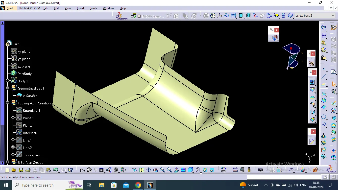
Tooling Axis Creation
To create tooling axis , following methods were used -
- First of all intersection of A Surface was taken along the complex surface.
- A line was generated to give a perspective idea for tooling axis, the two opposite lines were non-parallel to each other.
- Line was drawn using bisecting method using those non-parallel lines .
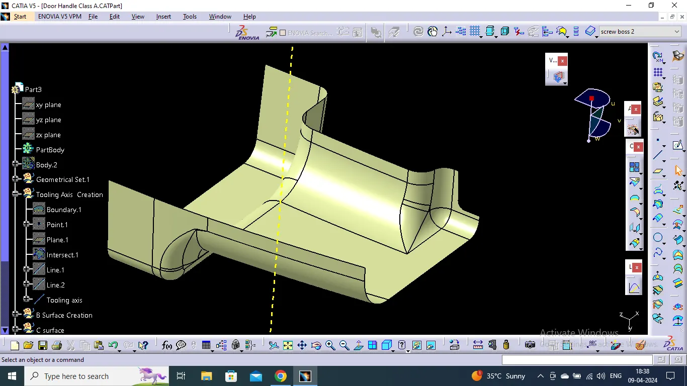
B-Surface Creation
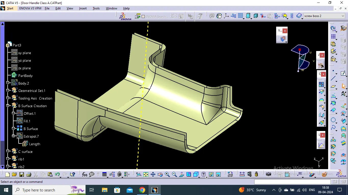
To create B-Surface following steps were taken,
- The A-surface was offseted by 2.5mm as given in question along the tooling axis.
- Some complications, were reasonably rectified using fill command.
C-Surface Creation
To create C-Surface following steps were taken,
- Using the boundry command Separate boundaries were created for seperate curves.
- All the curves were then sweeped along or pendicularly to the tooling axis according to their respective to their direction with draft angle (3 degrees).
- If needed some curved surfaces were generated using multisection command with the help of spline and multi-extracting curved lines.
- After all the surfaces were generated successfully, all the curves were joined using join command.
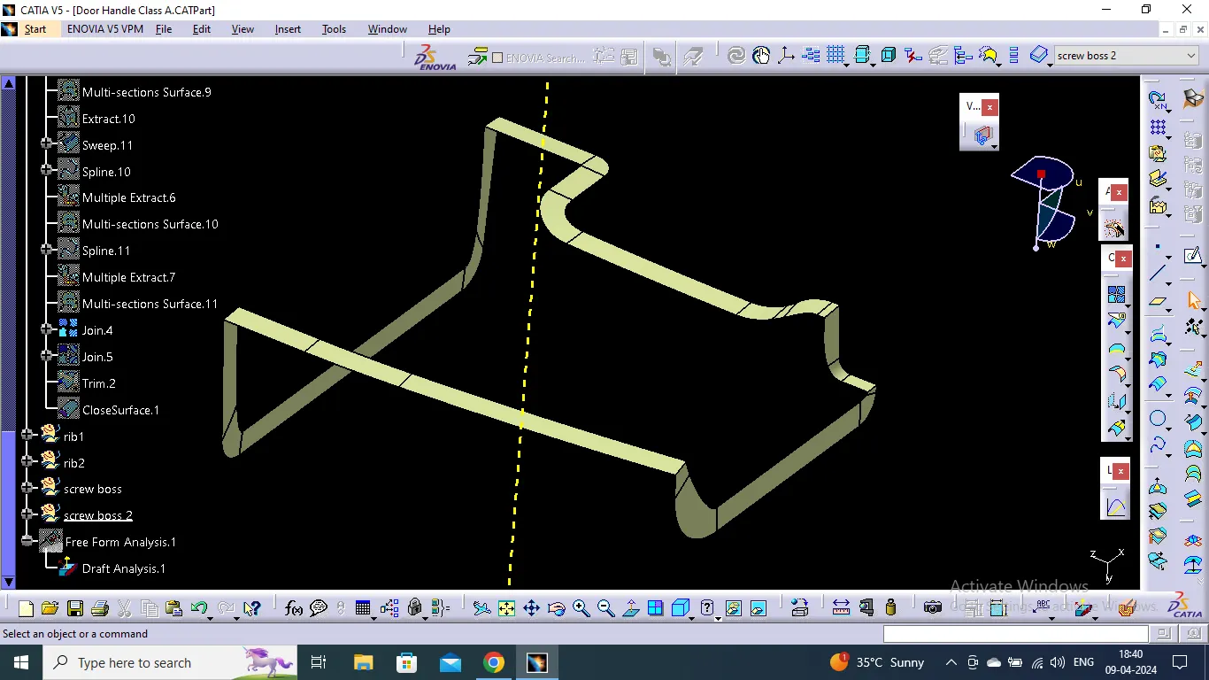
Creation od A-C Surface
After the creation of C Surface was completed , the A- Surface was joined to C-Surface using Join Command.
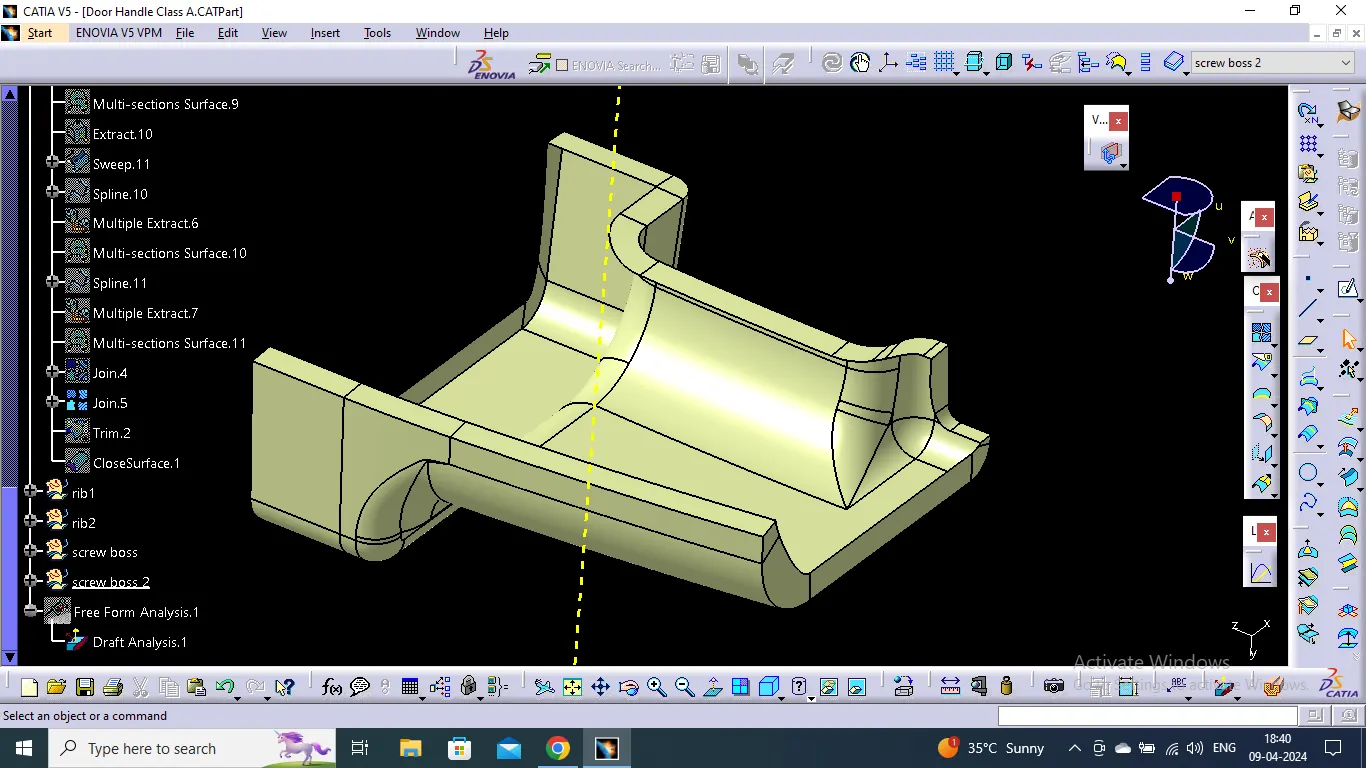
Creation of Closed Surface
After creation of A-C surface the whole surface is made to get trimmed with B-Suface to get a closed surface.
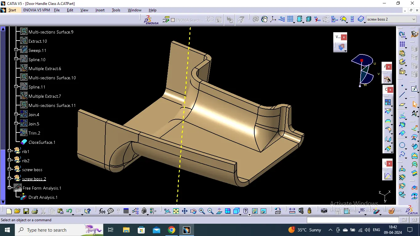
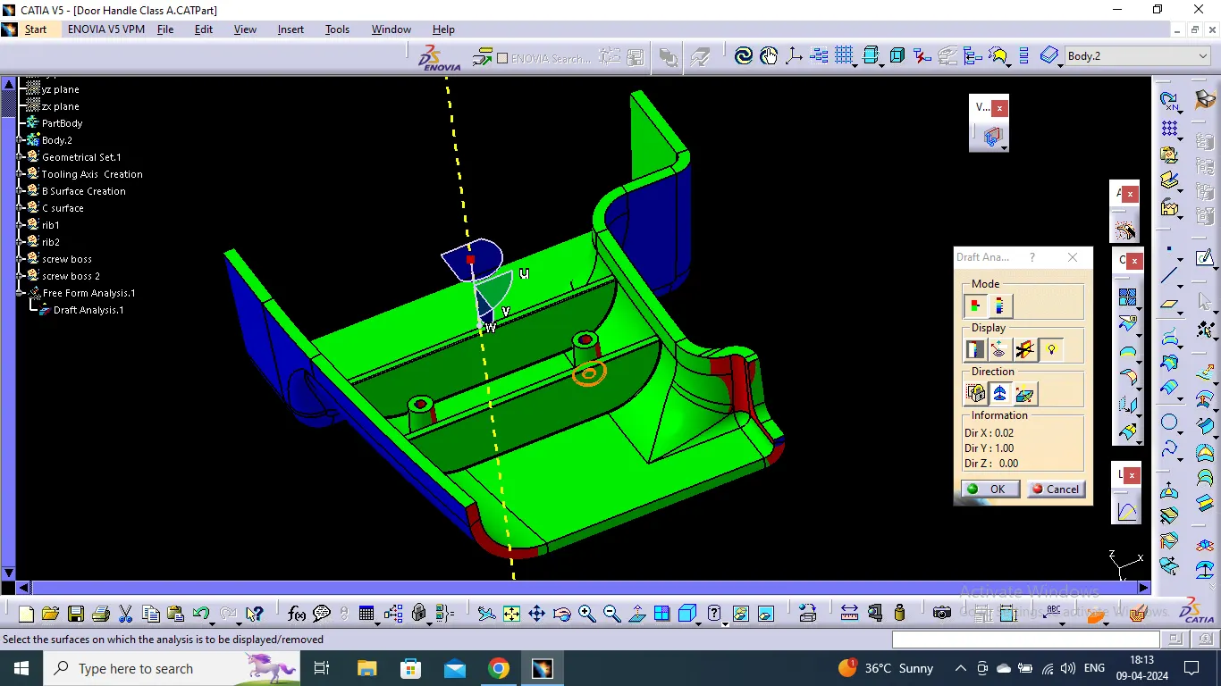
Generating Draft Analysis for Closed Surface
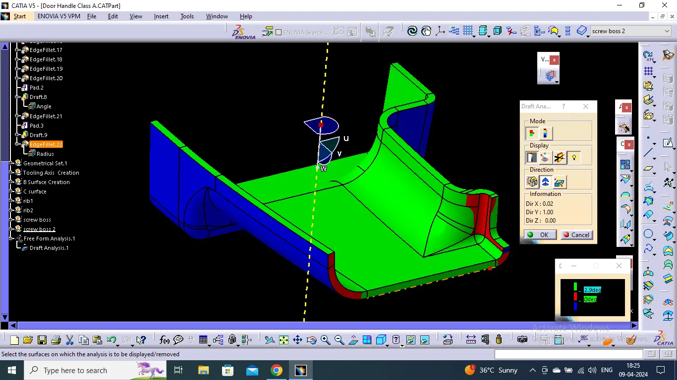
To genrate a draft analysis ,
- The material mode made to be ON at that time.
- Place the compass over the tooling axis in required direction.
- Click anywhere on the plane surface .
- The draft analysis would be generated , check the angles and color codes (2.9 degrees was in our case)
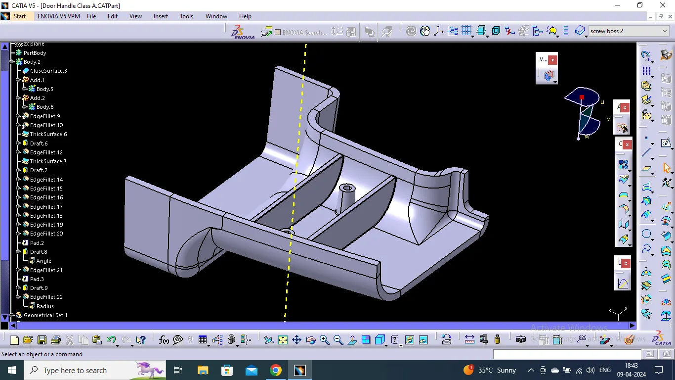
Creation of Ribs and Screw boss
To creat ribs and screw boss,
- For ribs intersections were taken at proper distances using a simple plane, sketch generated was filled and then thickened using thick surafce command , proper draft angles were given( 3 degrees in this case) and at last proper fillets were provided.
- For screw bosses, the plane was taken at a certain height (3 times the thickness of component) to create a hollow circular sketch, then it was padded upto the surface and then a draft angle of 3 degrees was provided accordingly, then it was filled at the joined corners by 0.25mm minimum radius fillets.
Draft Analysis of Closed body with Ribs and screw boss
At last, draft analysis was done on the final product as done in the previous draft analysis.
For any further clarification , the zip files have been attached below which contains part file and other screenshots.