Week 10 - Challenge 1- Attachment Feature Creation (Ribs & Screw Boss)
B-SIDE FEARURES DESIGN
(RIBS & SCREW BOSS DESIGN)
Objective:
To create a ribs & screw boss for drill handle by following design rules and perform Draft Analysis on the final plastic component.
Introduction:
In this project we are designing a drill handle component using given class A surface. The approach includes creation of class B surface keeping 2.5mm thickness in mind for complete component. The design also included class C creation from the given parent surface. After that we have to create the ribs and screw bosses to the drill handle component.
Class A Surface:
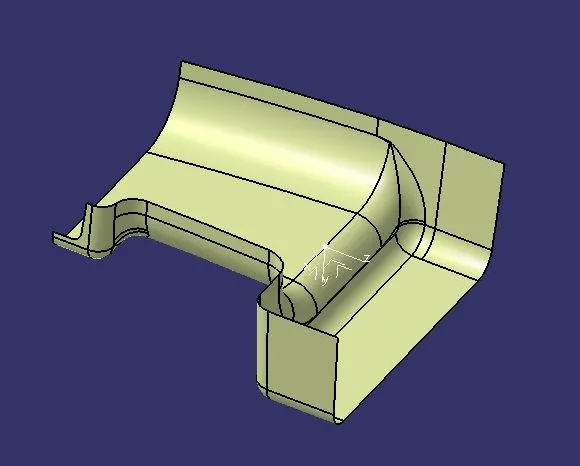
The given input surface is considered as Class A surface. Before creating a tooling axis, we have to check the connectivity of the surface and ensure there is no gap between the surfaces.
Tooling Axis:
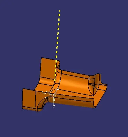
The direction in which the mold would open and close is called tooling axis. While creating the tooling axis give the tooling axis on a flat length surface or the surface which have a hole on it.
Create a point on the surface where we are going to create the dummy tooling axis and using line command create an axis. If there is a circle or flat length surface which is recommended. In this model we have to create a bisecting line by using two dummy tooling axis X and Y direction.
Draft Analysis:
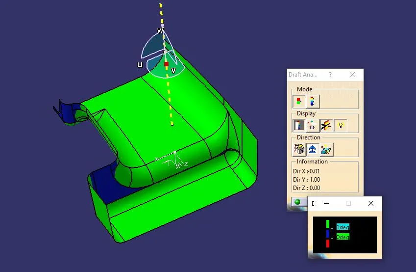
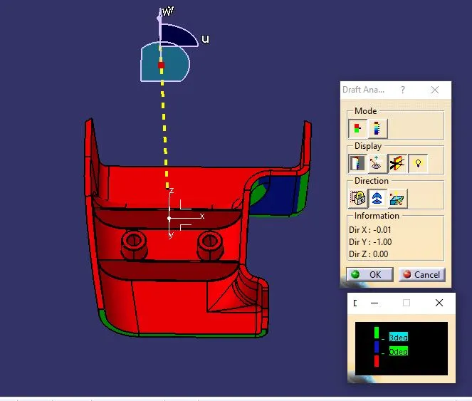
The draft analysis technique is used to analyze whether our part model created in CAD is manufacturable based on the draft condition applied. Here the part should get easily removed from the panel dies or mold.
No parts can be ejected from the tool if it is having 90° profile from its base surface. A small draft angle is provided to each and every area of the component in order to get easy removal of the component from the tool.
Here we are providing a direction in which components from the tool. In other word it also lets us know whether the model is having a draft angle and how much is the draft angle from the tool direction.
Class B Surface:
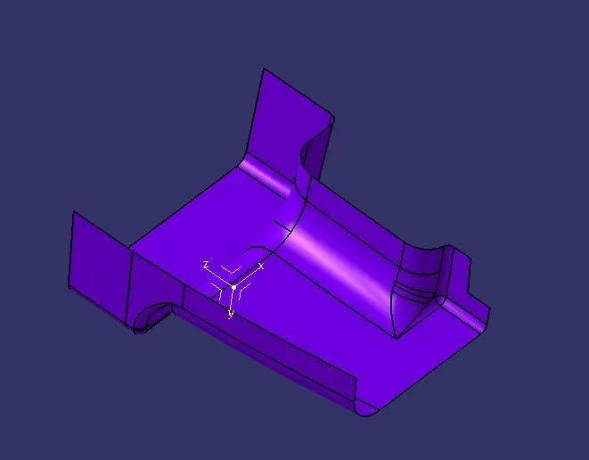
Class B surface is an offset surface to create a closed volume. To create a B surface, we have to offset the input surface in downward direction about 2.5 mm thickness. The offset surface is called Class B surface.
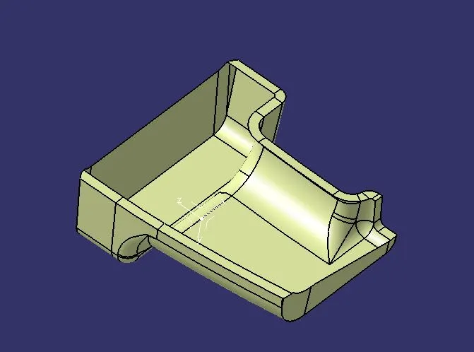
Class A and C Join:
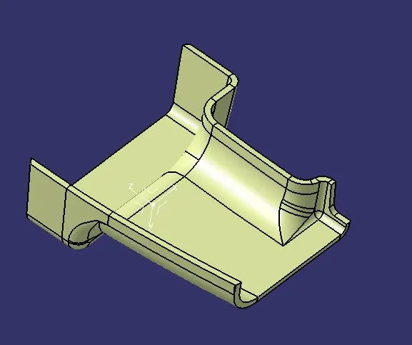
Final Trim:
Rib Design Rules:
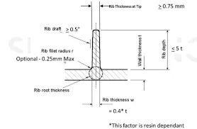
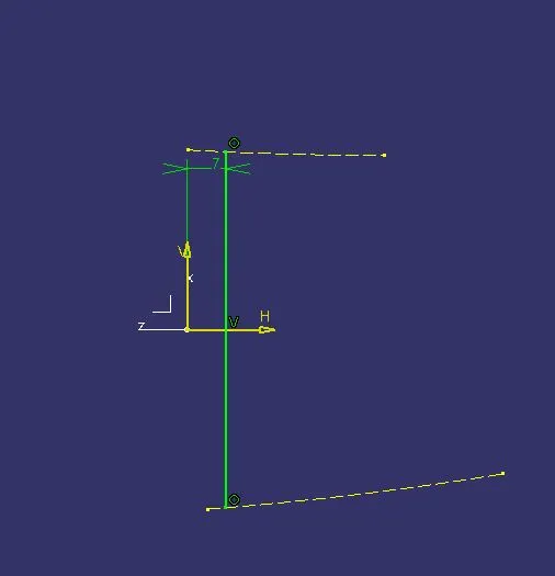
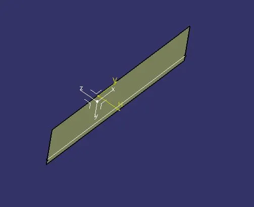
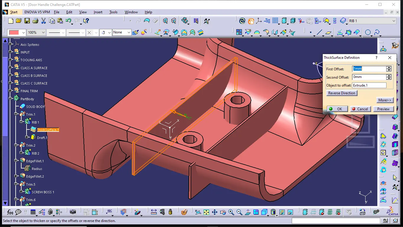
Ribs, in the context of plastic molding, are structural features incorporated into the design of plastic parts. They are thin, elongated projections that extend perpendicularly from the walls or surfaces of a plastic component. These ribs are strategically placed to provide reinforcement, improve rigidity, and distribute loads effectively within the part. Rib design in plastic parts is crucial because it significantly enhances the strength and performance of plastic parts.
Screw Boss Design Rules:
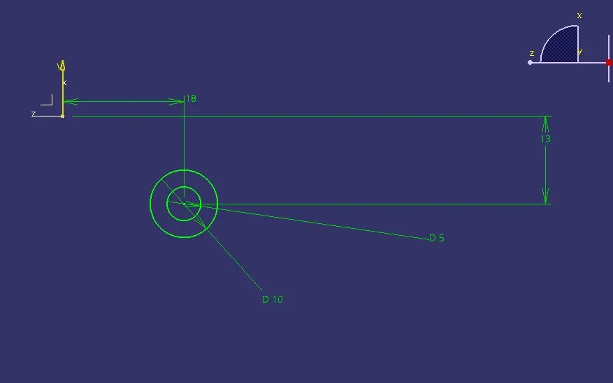
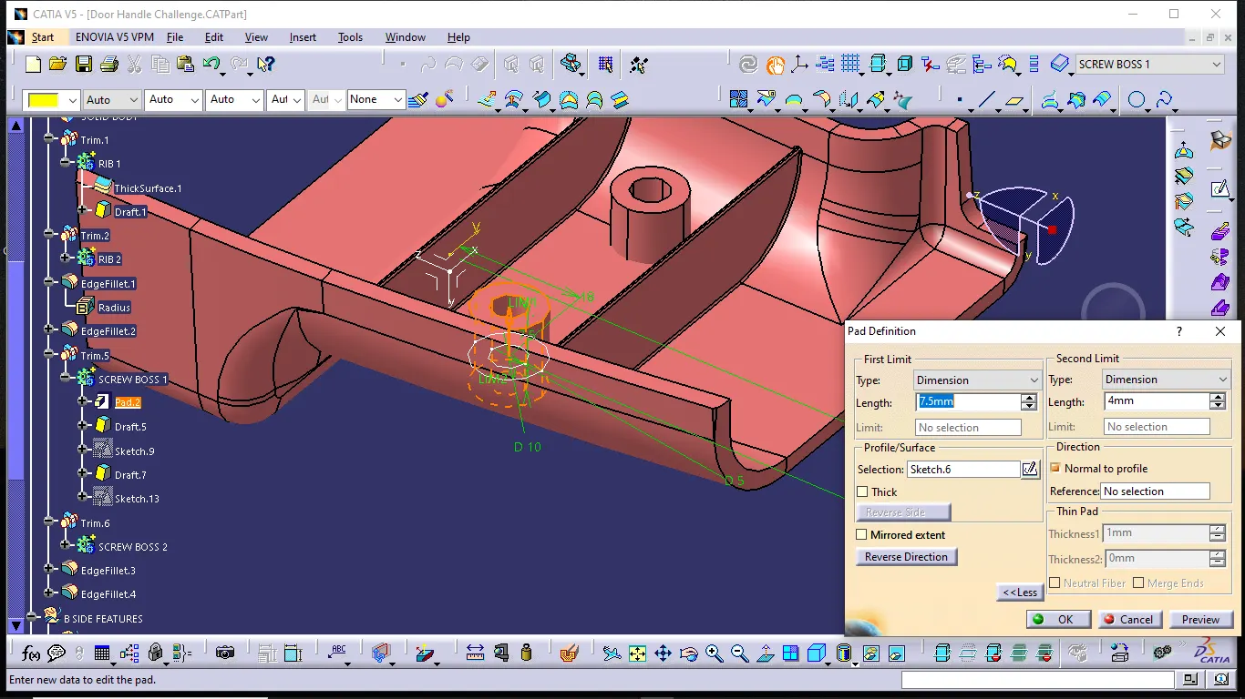
Screw bosses play a crucial role in molded parts as an attachment and assembly point. They are cylindrical protrusions that are typically located on a part’s wall and contribute to various functions such as positioning aids, fixation points, facilitating gear rotation, and acting as bearing surfaces or levers.
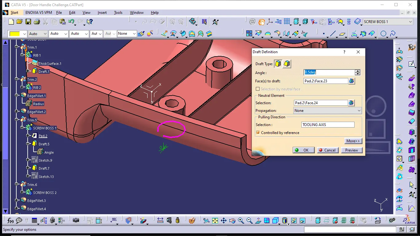
Ribs & Screw Boss:
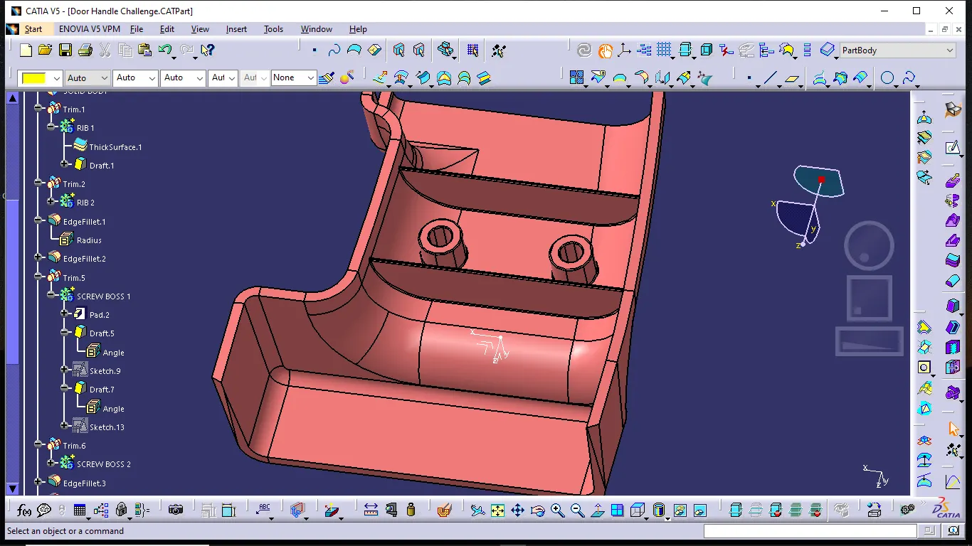
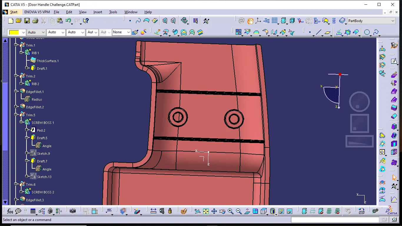
Orientations:
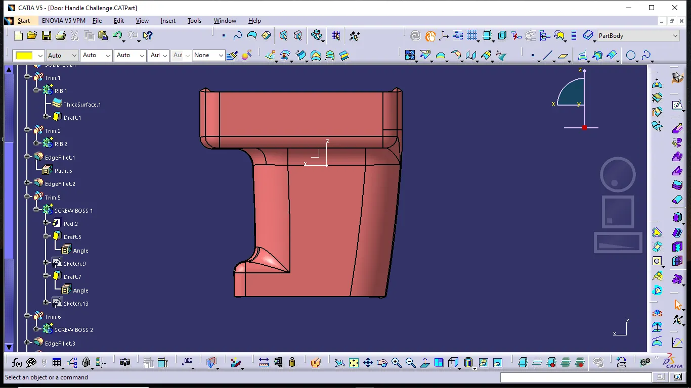
Front View:
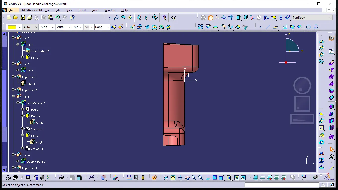
Right View:
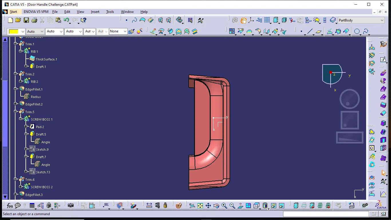
Top View:
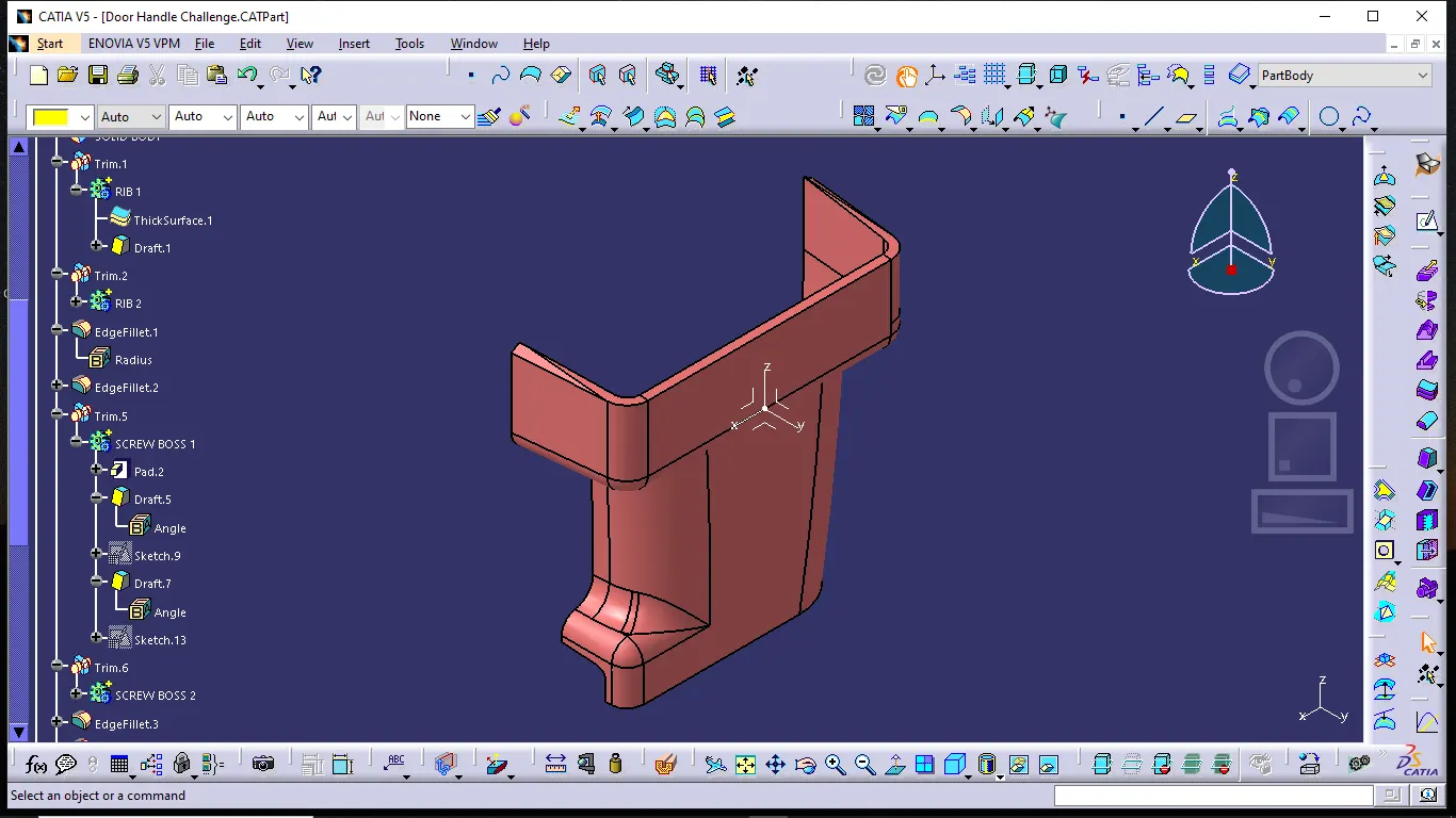
Isometric View:
Draft Analysis on Final Part:
Conclusion:
Thus, the ribs and screw bosses are created for the drill handle by following the deisgn rule and the draft analysis performed on the final plastic component.