Fender Design - Wheel Arch Challenge
Fender Design Wheel Arch Gap Calculation
Objective:
To calculate the wheel arch gap at required points and check whether the car passes the European standard.
Introduction:
Fender
Fenderis the part of an automobile, motorcycle or other vehicle body that frames a wheel well(the fender underside). Its primary purpose is to prevent sand, mud, rocks, liquids, and other road spray from being thrown into the air by the rotating tire. Fenders are typically rigid and can be damaged by contact with the road surface.
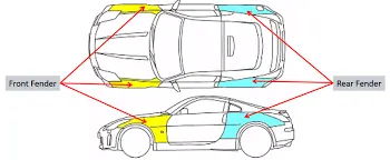
- The main purpose of fender in car is protect the pedestrains and the passenger from stones, mud and other debris that can fly in the air because of the speeding rotating wheels while the car is running.
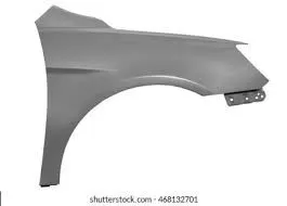
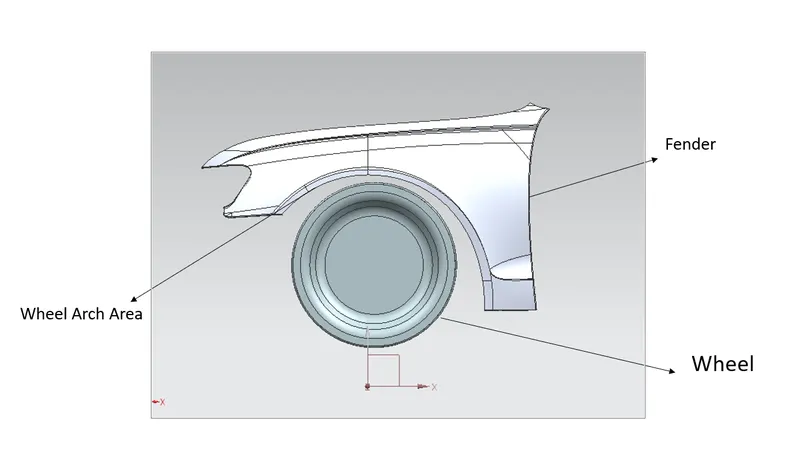
Fender - Wheel Arch:
Wheel Arch is the semi-circular part of the fender positioned above the wheel of the vehicle. The design of the wheel arch of the fender should be such that it must shield wheels and protect both passengers compartment and pedestarians from the projection of water, mud and stones.
Fender Wheel Arch Regulations:
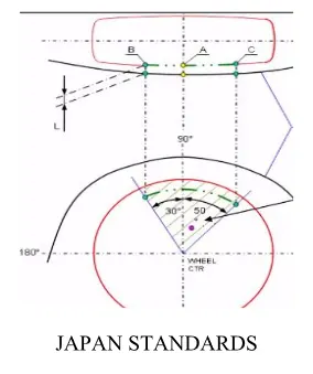
Japan Regulations:
According to the Japan standards the distance between the wheel and the fender should be the minimum 5mm distance.
European Regulation:
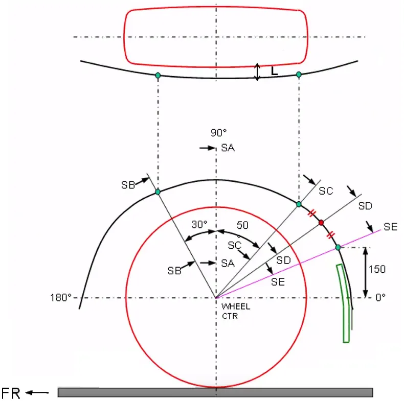
As per the European standards, the value of 'L' should be greater than 10mm. But at Section SB, the value of L is equal to 10mm and at other sections the value of 'L' is less than 10mm.
US Standard:
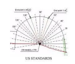
As per US regulation, the clearance between tyre and fender must be greater than 5mm. The projected points to be measured are at an angle 0° forward to 100° respectively. Thus each position is divided into 10°.
Calculation of Wheel Arch Gap based on European Regulation:
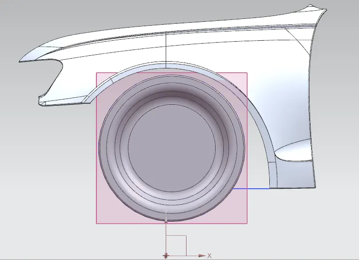
- To calculating the wheel arch gap between the fender and wheel we have to create a sketch at the outer most face of the wheel.
Before start a sketch of the wheel we have to create a datum plane on outer most face wheel.
- After creating a datum plane draw a horizontal and vertical line for reference. Then draw two line 30° & 50° from the vertical line respectively. After that create a point at 150mm distance from the horizontal line.
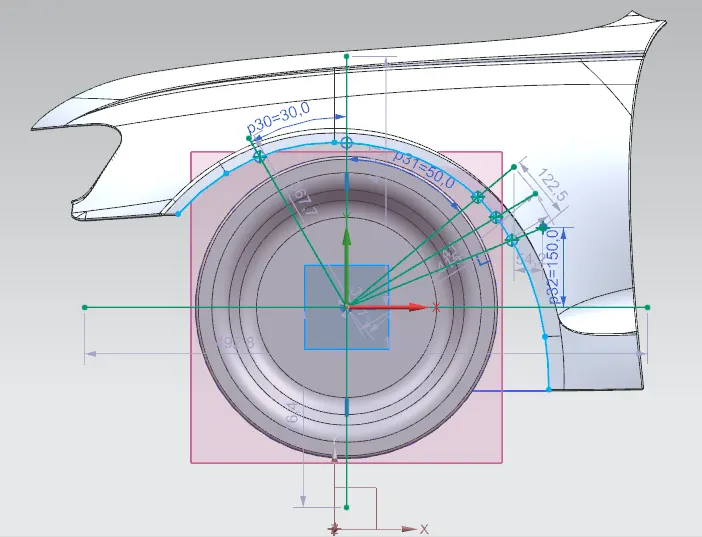
- Once the sketch is completed create a intersection point and project the points to the fender and name it as SB, SA, SC, SD, SE.
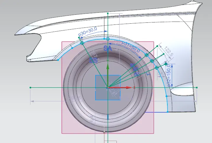
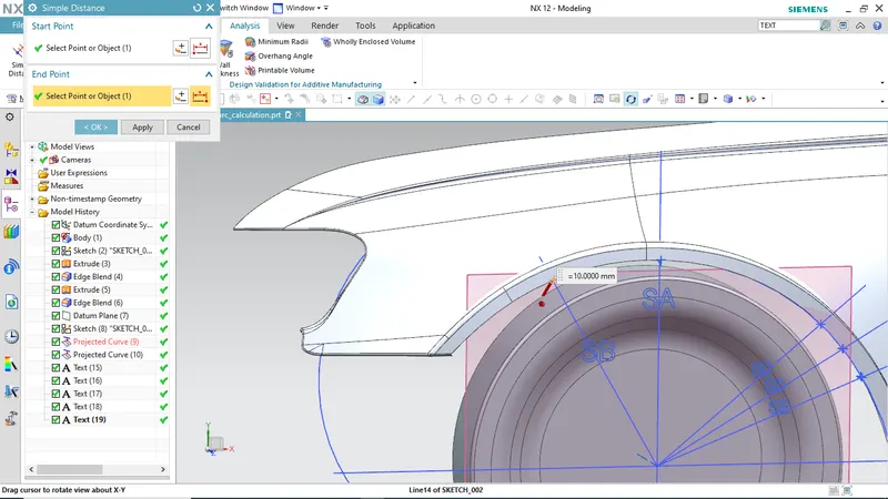
- After Sketch completed we have to measure the “L” distance by using the measure the simple distance command. First measure the distance of SB-SB and the observed distance is SB-SB = +10.00.
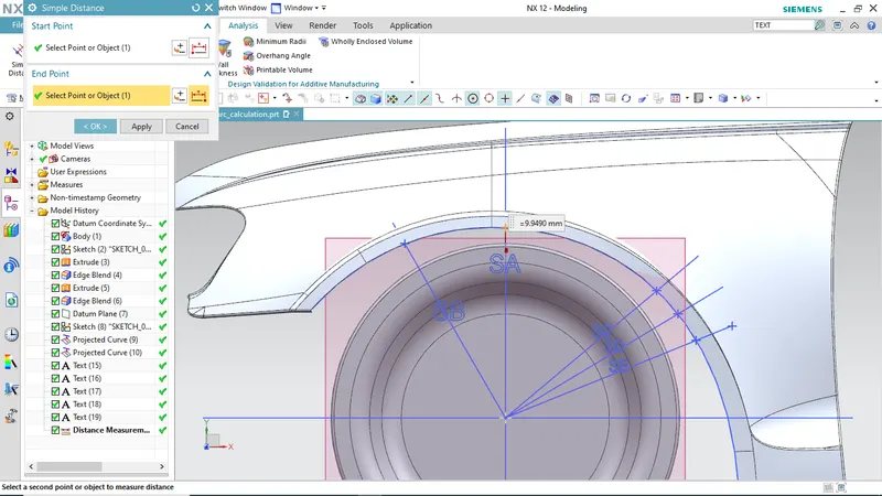
- Calculate the distance SA-SA = 9.9490.
- After calculating SB, SA, calculate the distance SC, SD, SE as shown in figures.
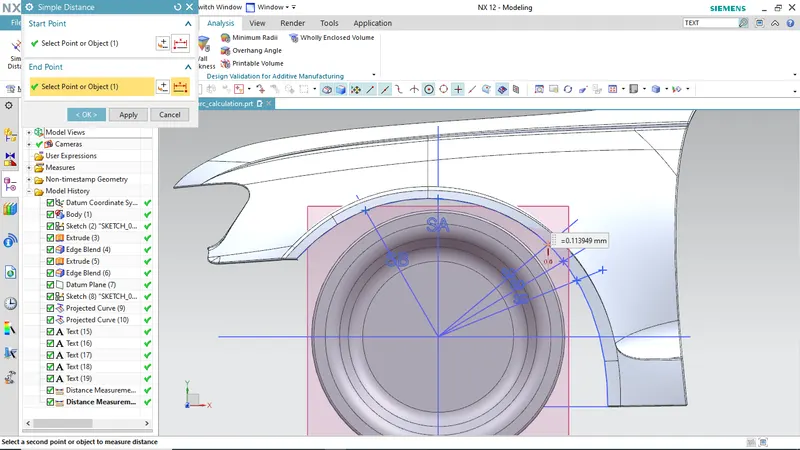
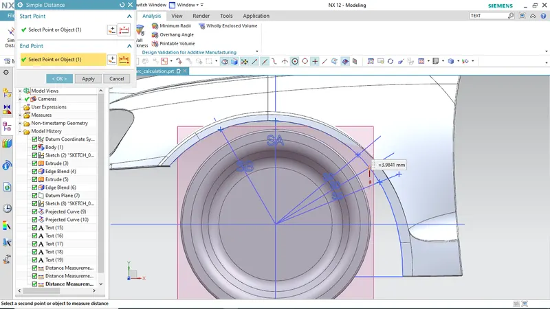
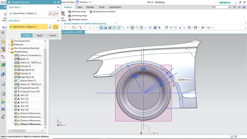
The above calculation results are tabulated below:
|
S.NO |
Section |
Clearance ‘L’ |
Result |
|
1. |
SA-SA |
+9.9490 < 10 |
FAIL |
|
2. |
SB-SB |
+10.0000 = 10 |
PASS |
|
3. |
SC-SC |
-0.1139 < 10 |
FAIL |
|
4. |
SD-SD |
-3.9841 < 10 |
FAIL |
|
5. |
SE-SE |
-8.4740 < 10 |
FAIL |
Conclusion:
Thus from the above results we can conclude that the fender does not pass the European regulation and this design does not meet the design requirement.