Week 10 - Challenge 1- Attachment Feature Creation (Ribs & Screw Boss)
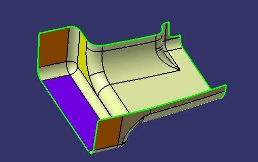
Class A Boundary Check
Creating A Tooling Axis
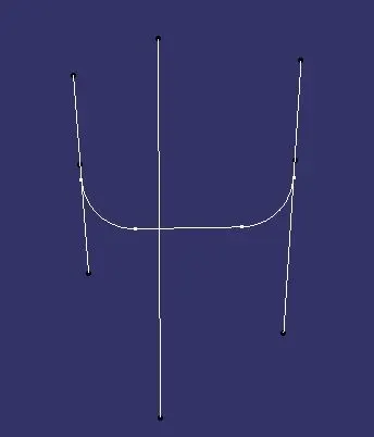
The direction in which a part is pulled out of a mould is known as the tooling direction. The mould is constructed out of two independent components. You have the Core side and the Cavity side. The Die line or Tooling Direction is when the Core separates from the Cavity.
Bisecting Lines
Compare the yz plane to the class A surface and intersect it.
Put point-to-point lines where there are alleged drafts and conceal the class A surface.
To establish a tooling axis, create a bisecting line by connecting the two lines.
BISECTING LINES were employed to separate the medium from the two sides to obtain the most positive draught angle possible.
Two axes from the x and y planes are divided to generate the tooling axis for the component.
Class B
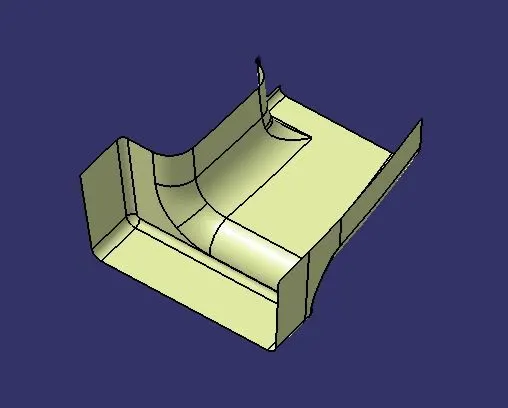
Using multiple extracts, separate the surfaces from class A and untrim them.
To construct the thickness, offset the surfaces to 2.5 mm using Extrapolate to ensure that all of the untrims are appropriately intersected.
Use the trim command to trim the superfluous surfaces.
Add them to the new geometric set and give it the names of the corresponding parts.
After finishing the model's full surface, add fillets.
For example, if the component's thickness is 2.5 mm and the fillet value is 15 mm, the outside portion value should be 17.5 mm, and the inner edges should be filleted 12.5 mm to achieve uniform thickness. The fillet value is added to the component's thickness if the edges are on the outside, and subtracted from it if the edges are on the inside.
Trims should be carried out one at a time to ensure clarity.
Class C
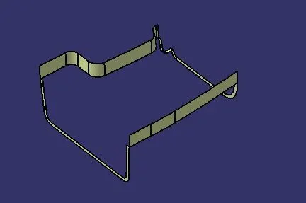
Use the boundary command to extract the border from the class A surface.
Using a disassembly tool to separate the boundary because it has domains.
Employ the sweep command, then select the profile type line, a subtype with draught direction, guide curve, draught direction, draught angle of 3, and preview options.
After obtaining the sweep, trim the output with a class B surface to obtain the desired result.
Now make a solid of the component using the open part design workbench and a closed body surface.
Various Orientations
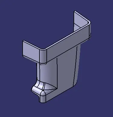
Isometric
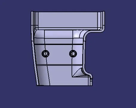
Side
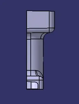
Front
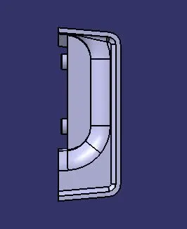
Top
Conclusion
As per above guidelines door handle is created by using class A surface, ribs and screw bosses are also created by following all the guidelines mentioned