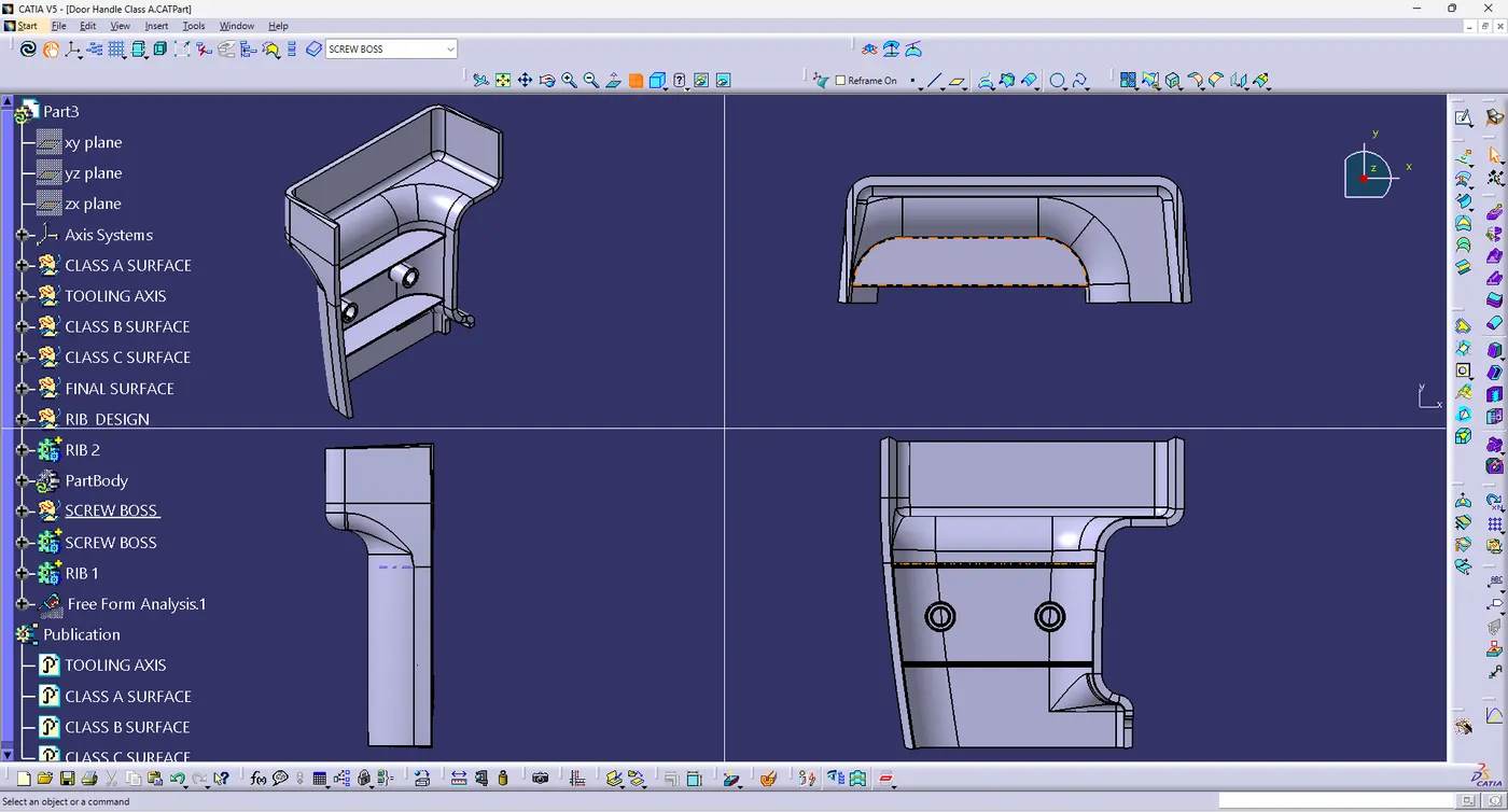
Week 10 - Challenge 1- Attachment Feature Creation (Ribs & Screw Boss)
RIBS & SCREW BOSS
- RIB DESIGN :-
Ribs provide a mean to economical stiffness and strength in molded parts without increasing overall wall thickness.
they also facilitate
- Locating and arresting components of an assembly
- providing alignment in mating parts
- Acting as stops or guides for mechanisms .
- proper Rib Design involves five main issues:-
- THICKNESS
- HEIGHT
- LOCATION
- QUANTITY
- MANUFACTURABILITY
CONSIDER THESE ISSUES CAREFULLY WHEN DESIGNING RIBS
- GUIDELINES FOR RIBS ON SHOW SURFACES :-
- DRAFT
- THICKNESS
- HEIGHT
- SPACING
- THICKNESS AT TOP
- OPTIONAL RADIUS
- DESIGN SUGGESTIONS
- Draft 0.5 deg. per side minimum
- W=0.4*t (Typically 40%wall thickness)
- measure base thickness of rib at tangent of radies if radil are modeled in
- the larger the area at the base of the rib, the more retained heat
- the retained heat causes more shrinkage ,which causes sink
- minimum thickness at top of the rib =.75mm
- optional Rib fillet radius= .25mm maximum (do not want to significantly increase rib thickness must not violate 40%thickness requirement)
- Rib height <5x nominal wall thickness(limited by draft and thickness requirements)
- Rib should be spaced so that the steel between the ribs is
- hight / width ratio
3:1 steel
2:1 is preferred
| WALL STOCK(MM) | MAX RIB THICKNESS AT BASE @40%(MM) | MIN RIB THICKNESS @(MM) | MIN | MAX RIB HEIGHT (MM) |
| 2.5 | 1 | 0.75 | 0.5 | 14 |
| 3 | 1.2 | 0.75 | 0.5 | 25 |
- SCREW BOSS DESIGN :-
BOSSES FIND use in many part design as points for attachment and assembly. the most common variety consists of cylindrical projections with holes designed to receive screws, threaded insert or other types of fastening hardware ,as a rule of thumb, the outside diamenter of bosses should remain within 2.0 to 2.4 times the outside diameter of the screw or insert.
to reduce stress concentration and potential breakage, bosses should have a blended radius, rather than a sharp edge at their base , larger radii minimize stress concentration but increase the chance of sink or voids . specifying smaller screw or inserts oftenn prevents overly thick bosses.if the boss wall thickness must exceed the recommended ratio, consider adding a recess around the base of the boss to reduce the severity of sink.
avoid bosses that merge into sidewalls because they can form thick section that lead to sink . instead position the bosses away from the sidewall, and if needed use connecting ribs for support.
normally , the boss hole should extend to the base wall level, evem if the full depth is not needed for assembly
- DESIGN RULES FOR SCREW BOSS :-
- DRAFT
- THICKNESS
- HIGHT TO DIAMETER RATIO
- OPTIONAL RADIES
- BOSS GUSSETS
- CORING OUT BOTTOM
- PLANNING AHEAD FOR TYPE OF EJECTION
- (W= 0.6*T)
- MEASURE BASE THICKNESS OF RIB at tangent of radius if radius are modeled in
- the larger the area at the base of the rib , the more retained heat .
- the retained heat causes more shrinkage , which causes sink .
- optional rib fillet radius - 0.25mm maximum
- must not vidate 40%thickness requirement
- 0.5 degrees on both inside and outside walls of boss
- different rules if sleeve ejection is used
- needs to be planned for
- height to diameter ratio (general rule H/B<3)
- USEING CATIA SOFTWARE :-
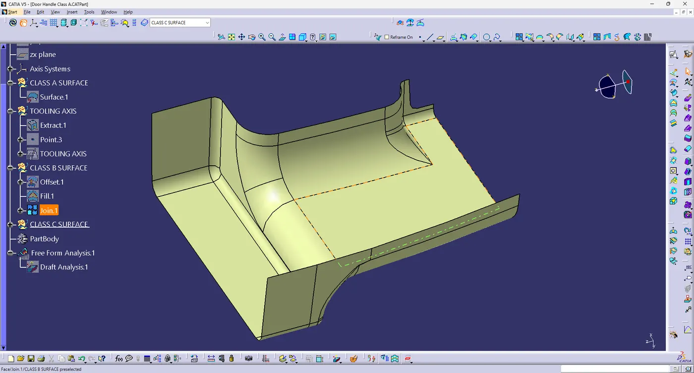
1. CLASS A SURFACE :-
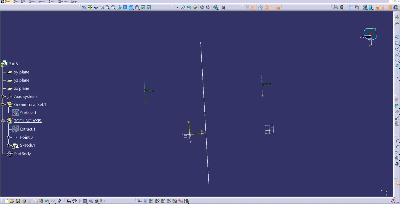
2. TOOLING DIRECTING :-
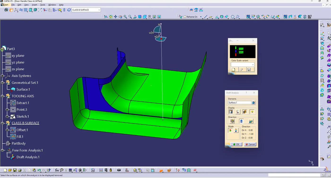
3. DRAFT ANNALYSIS ON CLASS A SURFACE :-
4. CLASS B SURFACE CREATE BY OFFSET METHOD :-
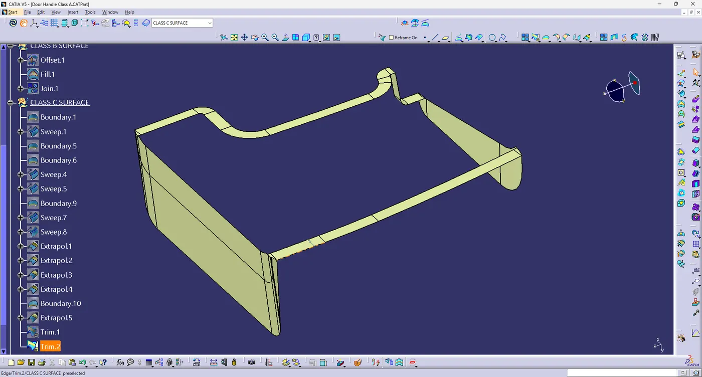
5. CLASS C SURFACE:-
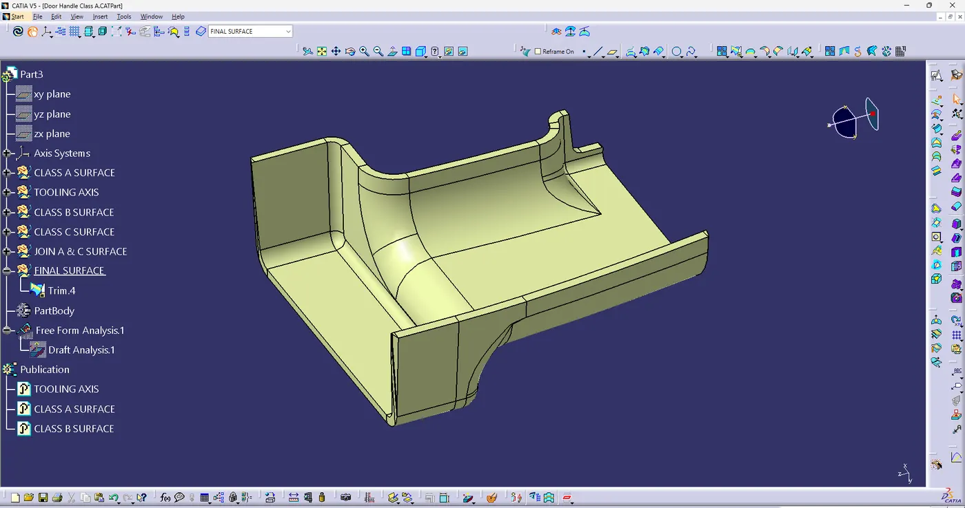
6. FINAL BODY :-
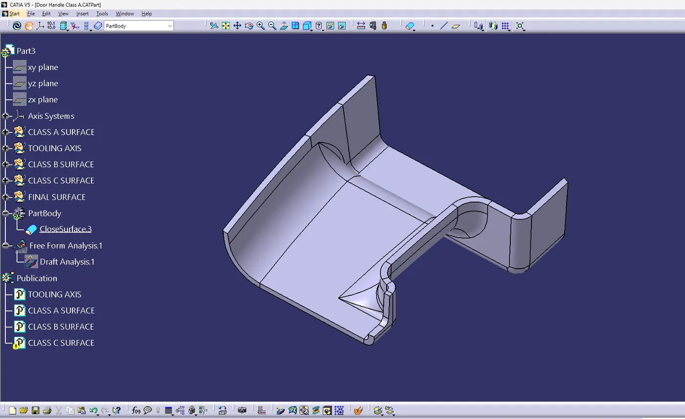
7. CLOSE BODY :-
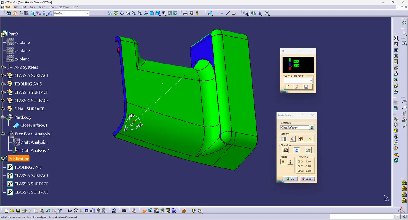
8. DRAFT ANNALYSIS ON CLOSE BODY :-
9. CREATE 2 RIBS :-
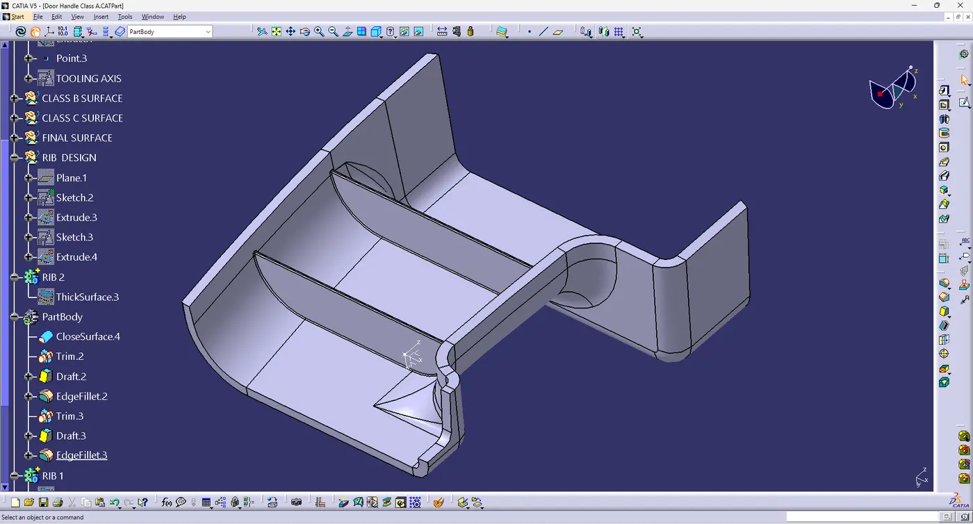
10. CREATE 2 SCREW BOSS:-
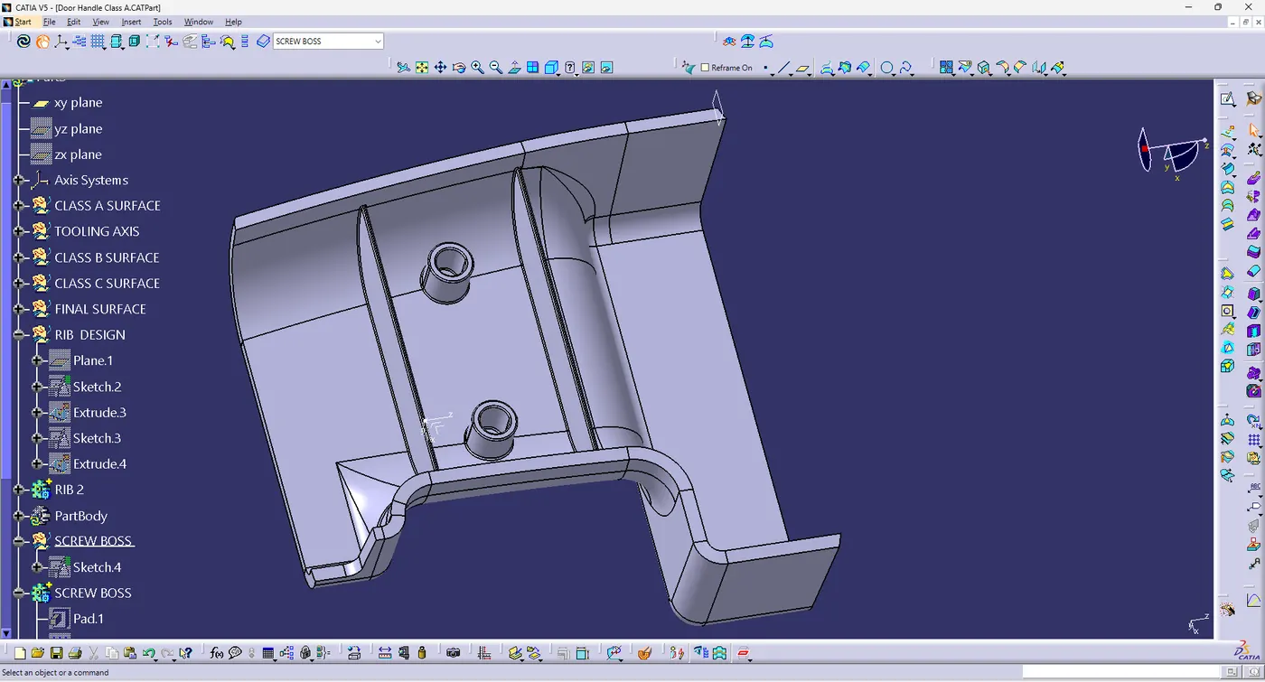
11. FINAL BODY DRAFT ANNALYSIS :-
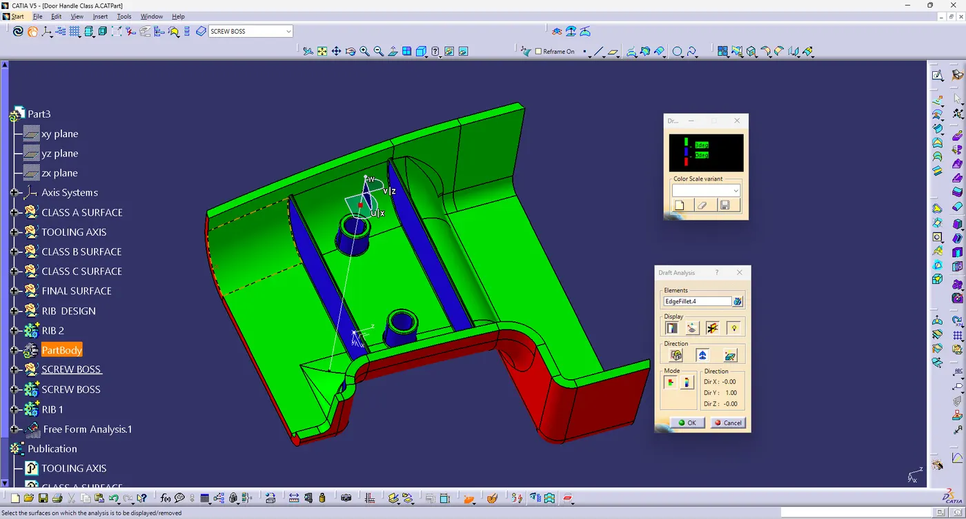
12. ALL VIEWS :-