Week 10 - Challenge 1- Attachment Feature Creation (Ribs & Screw Boss)
Objective:
The main objective of this challenge is to Create the rib for the Drill Handle considering the design rules. To Create the tooling axis for the given Class-A Surface meeting the requirements of the draft angle. To Attach B side Features in the component. To perform the Draft analysis on the model.
Procedure for the projects
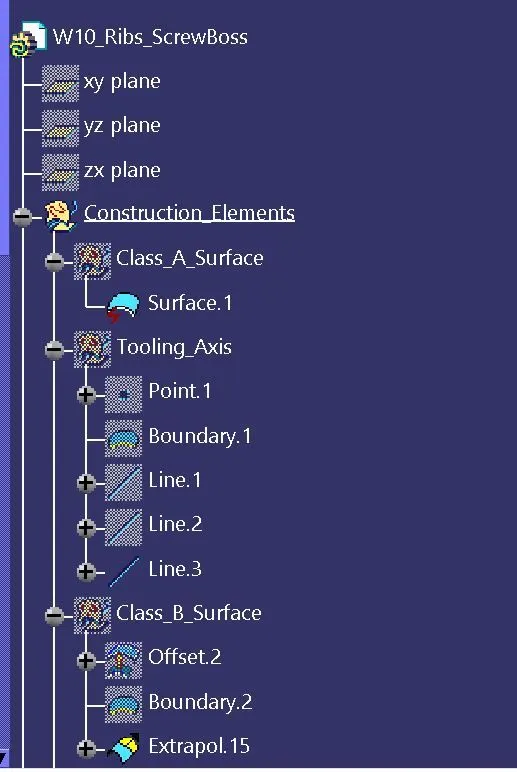
- Creating the tooling axis
- Draft analysis of Class A surface
- Creating Class B surface
- Creating Class C surface
- Surface and solid body
- Draft analysis of Solid body
- Engineering features Rib and Screw boss
Class_A_Surface:
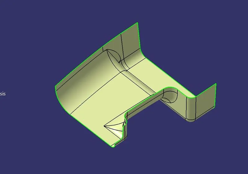
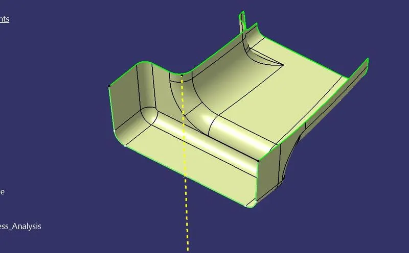
The above A_Surface is the source part for creating the B and C surface.
Tooling Axis:
To create the tooling axis first we have to check the best suitable direction for tooling by using the compass. I'm choosing one side edge for the tooling axis creation. Then using the bisecting line to create the tooling axis.
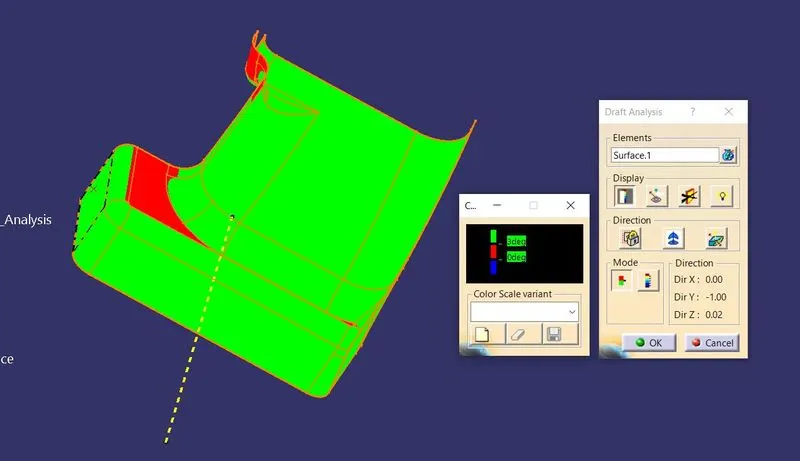
Draft analysis of Class- A
After creating a tooling axis we do the draft analysis. Before drafting we have to make sure that in the view mode it is selected for the materials.
After selecting the feature draft analysis tool we drag the compass from its position to the tool axis. Then lock the compass. After that select anywhere on the component and it will give you the result.
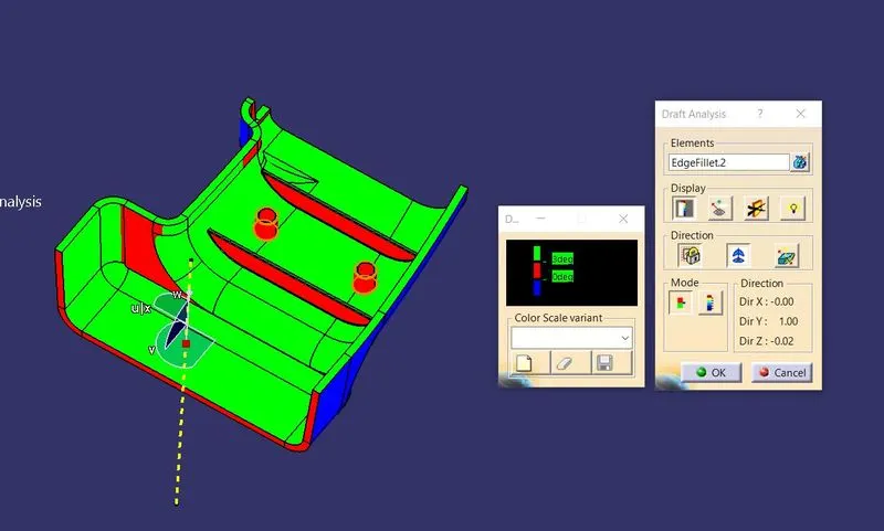
We change the minimum draft for the component to 3°.
We can use the running point option to check the angle of the component.
Class_B_Surface:
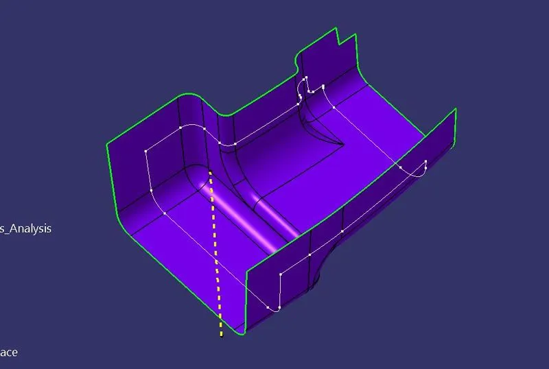
For creating the B_Surface, I'm using the A_Surface to offset it to 2.5 mm outwards. Then I'm using the extrapolate their edges by using the boundary option in it. Then there is no erors in it, so I'm using the Offset surface as the B_Surface.
Class_C_Surface:
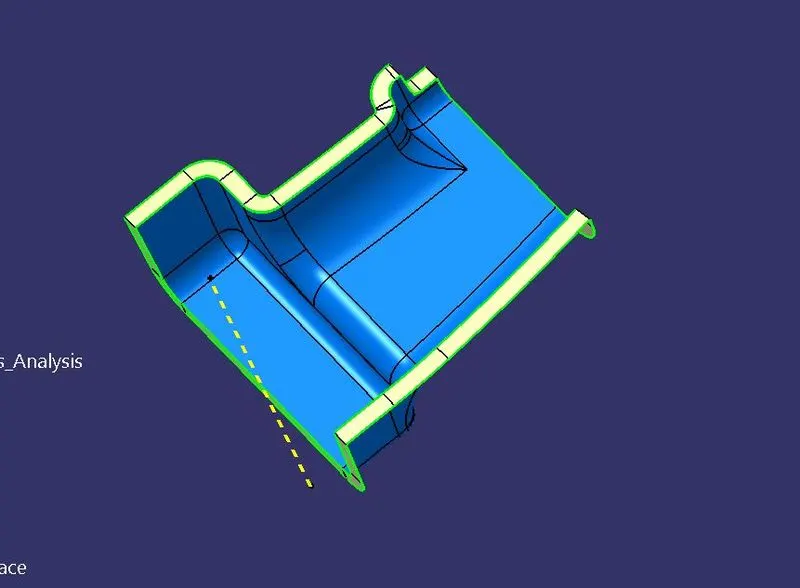
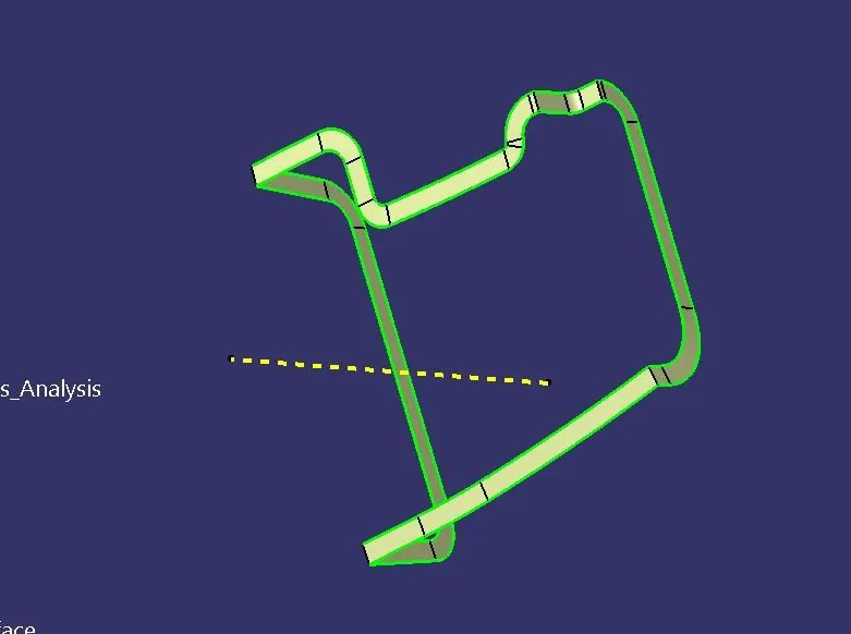
In this we are going to use the A_Surface edge boundaries to create the C_Surface for the by using the sweep tool.
Final Part Surface:
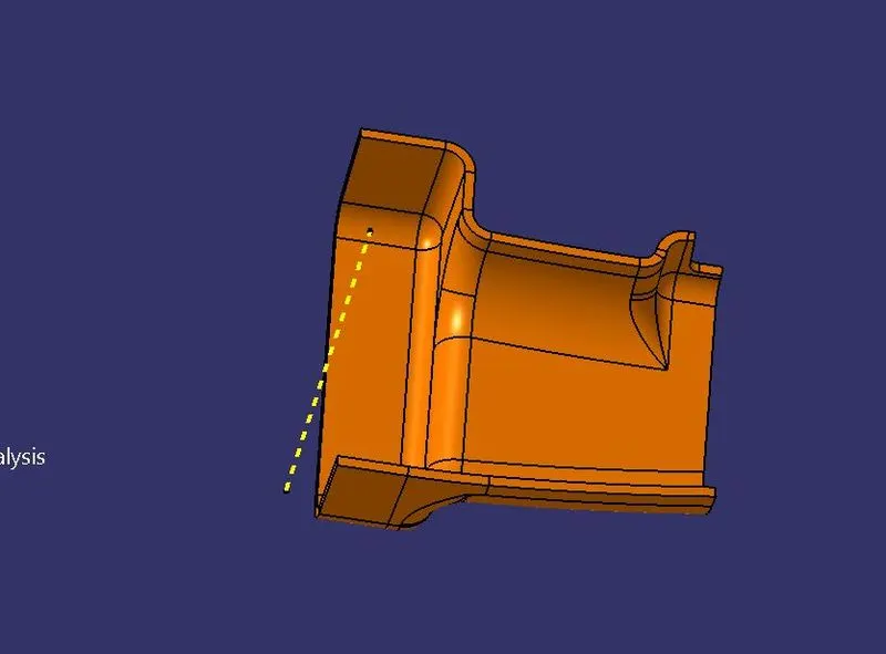
Then we are going to join the A_Surface and the C_Surface, later we'll get this surface. Then we can trim with the B_Surface, Later we'll get the final part surface.
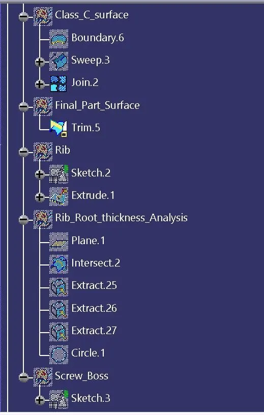
Rib Creation:
General Guidelines for Bosses:
- Draft - 0.5 degrees on the walls of boss
- Thickness - Typically 40%* of the nominal wall at the base.
- Height to Diameter Ratio - 3:1
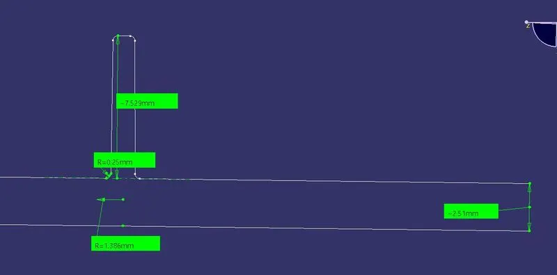
- Radii - 0.25mm maximum radii.
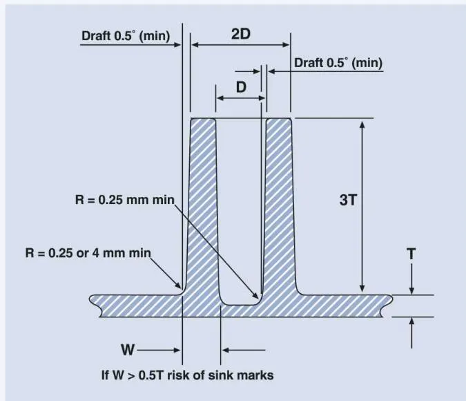
Rib provides an economical way to increase stiffness and strength to the mould parts without increasing the overall thickness of the wall. It is thin protrusion that extended perpendicular from the wall.
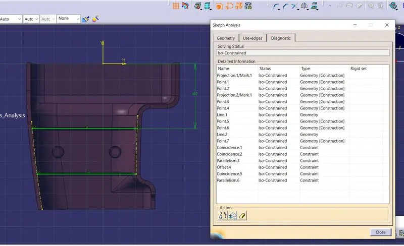
Sketch used for rib creation:
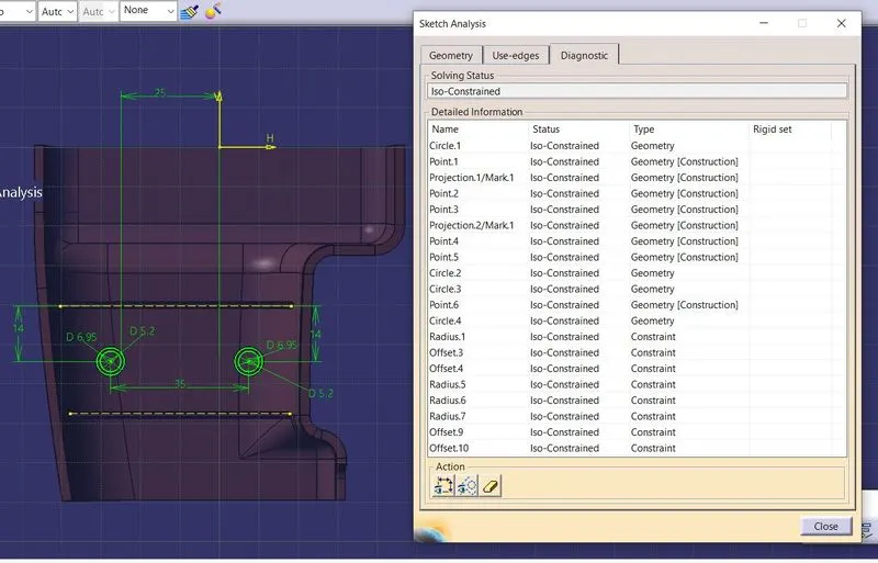
Sketch used for Screw Boss Creation:
Root thickness analysis:
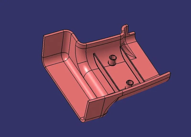
Final created Part:
Final Part Draft Analysis:
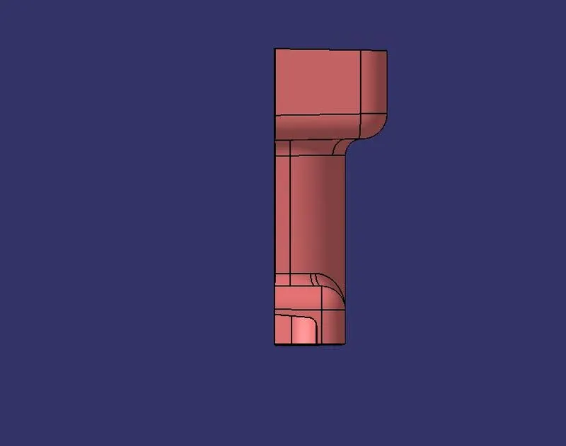
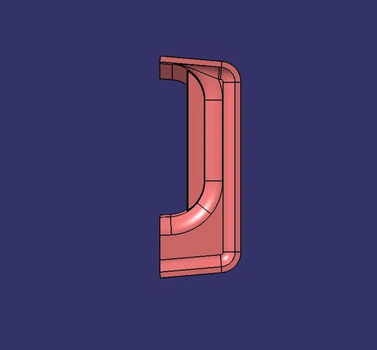
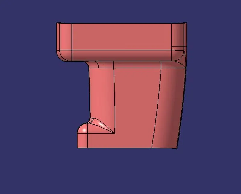
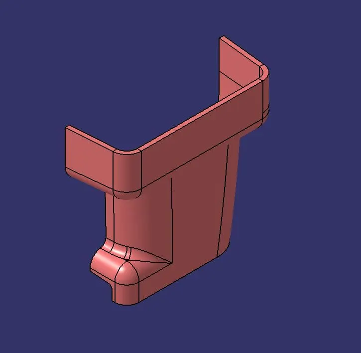
3D_Orientation of the final part:
Front View:
Top View:
Side View:
Isometric View:
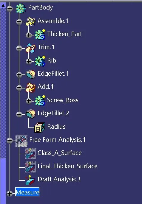
Tree Structure: