Week 10 - Challenge 1- Attachment Feature Creation (Ribs & Screw Boss)
Attachment Feature Creation (Ribs & Screw Boss)
-> Ribs are engineering features that can provide stiffness and strength in moulded parts without increasing the overall wall thickness.
They also help in:
- Locating components of an assembly
- Providing alignment to mating parts
- Acting as Stops or Guides for mechanisms
While designing Ribs we need to follow certain Design Rules:-
- Draft Angle: 0.5 degrees per side
- Thickness: Typically, 40% of the wall thickness
- Height: Less than or equal to 5 times the wall thickness
- The minimum thickness at the tip of the Rib should be 0.75
- Rib fillet radius of 0.25mm maximum
- Rib Root thickness can have a deviation of 30% from the wall thickness
-> Screw Bosses are used for attachment and assembly. It is an engineering feature that helps us to screw components together. We increase the height of the component at a specific area and have provision for the screw, this constitutes a Screw Boss.
Similar to Ribs and other B-Side Features, we need to follow a certain set of design rules to avoid plastic defects:-
- Draft Angle: 0.5 degrees on the walls of the Boss
- Thickness: typically 0.6 times the nominal wall thickness
- Height to Diameter ratio: 3:1
- Fillet Radius: 0.25mm
Class-A Surface of the Drill Handle provided as input:
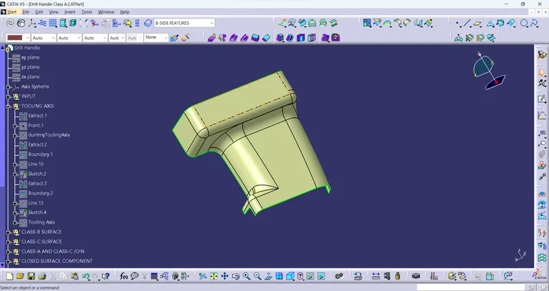
- Tooling Axis Creation:
We first study the Class-A surface from all directions to find the optimum direction to be the Tooling Axis.
X-Direction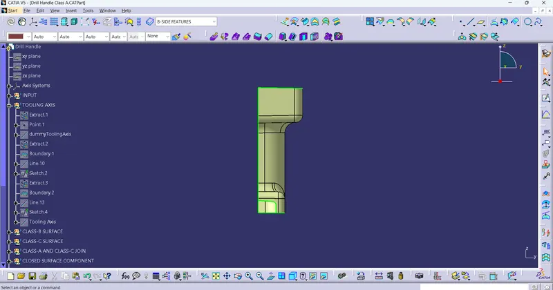
Y-Direction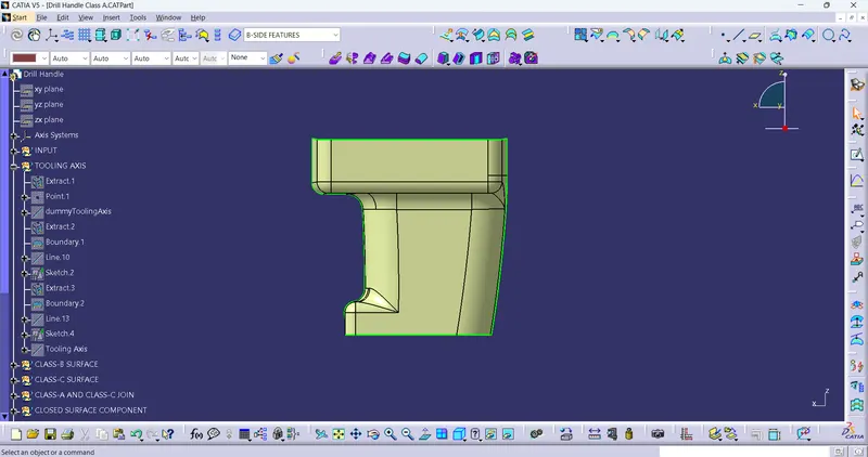
Z-Direction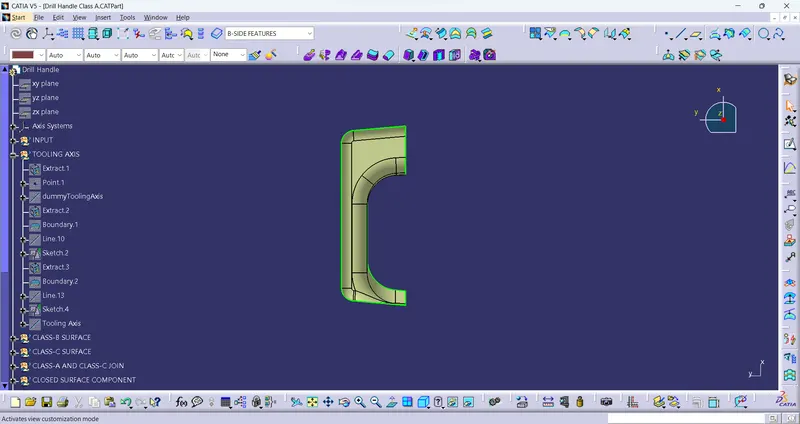
We find that from the Y-direction we can see the most surfaces and therefore we choose the Y-direction to be the Dummy Tooling Axis.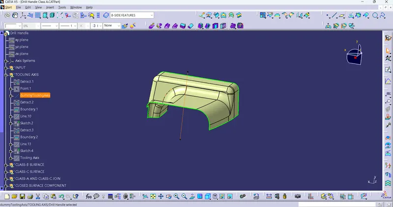
From the Draft Analysis of the Class-A Surface using the dummy tooling axis (image shown later), we find that some faces have an angle less than the Draft Angle (3 degrees) with respect to the dummy tooling axis.
Therefore, we have to optimize the Tooling Axis such that most surfaces of the part we are designing can be ejected easily and without any damage from the mould. We use the Bisecting-Line method to optimize the Tooling Axis.
- We create lines using the boundary of the problematic surfaces representing the orientation of the surfaces.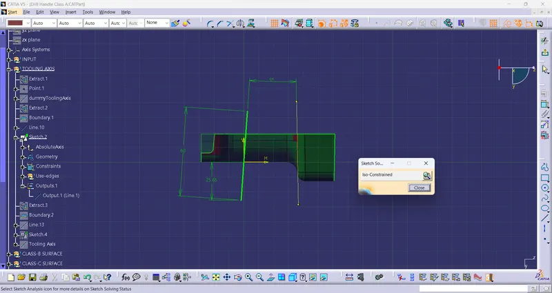
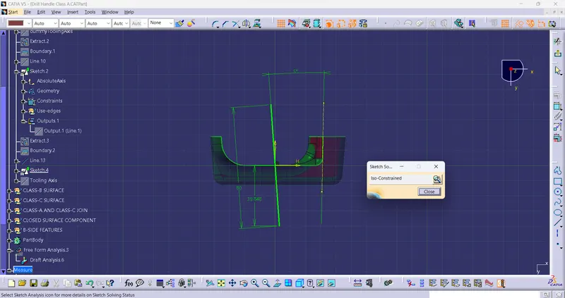
- Using these lines we create a bisecting line that represents the direction in which most surfaces could clear the mould. The line created is the Tooling Axis.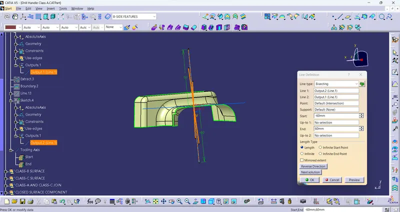
- Draft Analysis:
To check if we have selected the Tooling Axis correctly we perform the Draft Analysis. The result of the analysis shows us, using colour codes, which surfaces have an angle lower than the draft angle with respect to the Tooling Axis (in Red).
These surfaces may cause problems when we try to eject the part from the mould.
Therefore, we then adjust the Tooling Axis orientation to have as many surfaces in Green as possible, i.e. having an angle greater than the draft angle with respect to the tooling axis.
- Performing the Draft Analysis in the Class-A Surface using the Dummy Tooling Axis (Y-Direction):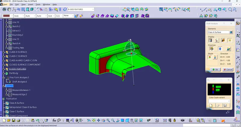
We can see from the image above that there are certain surface patches which are in the Red. Since these surfaces might get damaged during ejection we have to optimize the Tooling Axis.
- Performing Draft Analysis on the Class-A surface using the Tooling Axis: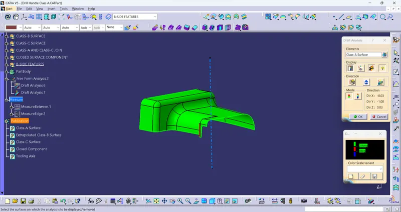
Most of the surfaces are now in the Green. There is a small patch that is still in the Red, for that, we may need to contact the Class-A modeller and ask them to provide Draft Angle to that surface.
- Performing Draft Analysis on the Closed Surface component using the Tooling Axis: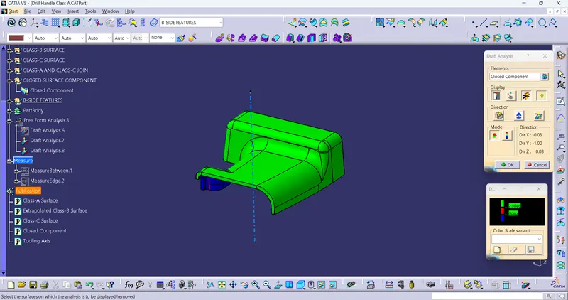
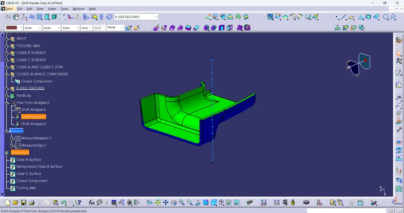
Once we have created the closed surface component using the Class-A, Class-B and Class-C Surfaces we perform the Draft Analysis again. This is done to check that the surfaces we created have the required draft angle i.e. the closed surface can be ejected easily from the mould.
- Finally, we perform Draft Analysis on the Solid Part (with all the B-Side Features) using the Tooling Axis: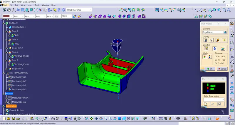
The result of the Draft Analysis on the Solid Part shows all the B-side features in Red because the Draft angle provided is 0.5 degrees as per the design rules.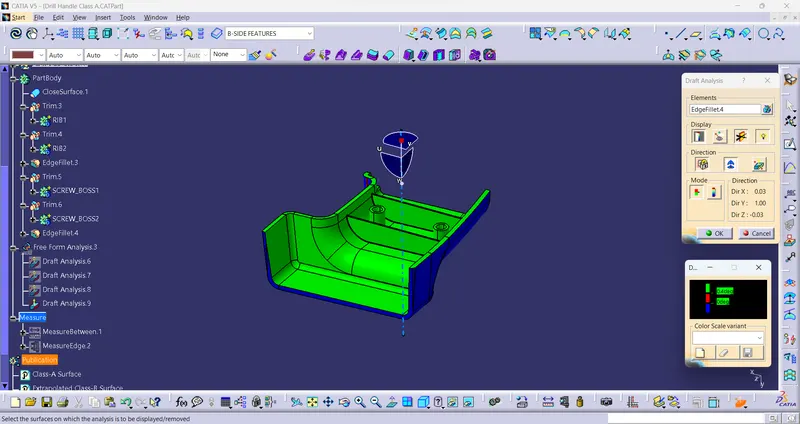
Editing the colour codes for the Draft Analysis results to include features with a draft angle of 0.5 degrees in the Green shows us that all the B-side features have the required draft angle.
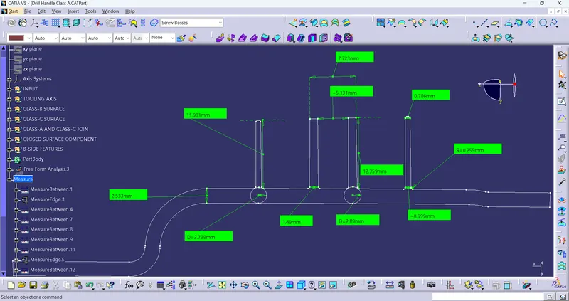
Before finalizing the part, we must also confirm that the B-Side Features follow the Design Rules:
The nominal thickness of the part wall is 2.5mm.
Ribs
- A draft Angle of 0.5 degrees can be confirmed from the Draft Analysis.
- The fillet radius provided is 0.25mm.
- The thickness of the Rib provided is 0.4*2.5mm = 1mm
- The thickness of the Rib at the tip is 0.786mm, greater than 0.75 mm as per the design rules.
- The height of the Rib is 11.9mm, less than 5 times the thickness of the nominal part thickness (5*2.5=12.5mm)
- The Rib Root Thickness is 2.72 mm, within the 30% deviation limit.
Screw Bosses
- The thickness of the Screw Boss is (0.6*2.5 =) 1.5mm.
- The fillet radius provided at the base is 0.25mm.
- Height to Diameter ratio is 2.5, less than 3 as per the design rules.
- A draft angle of 0.5 degrees can be confirmed from the Draft Analysis.
- Screw-boss hole depth is such that the root thickness is within the 30% deviation limit.