Week 10 - Challenge 1- Attachment Feature Creation (Ribs & Screw Boss)
AIM
Create the rib for the Drill Handle considering the design rules mentioned in the video.
DESIGNING OF RIB AND SCREW BOSS
TOOLING AXIS
Create a tooling axis for given class A surface . The first step is to examine the given class-A surface and consider the proper tooling axis .For the given class A surface Y -axis is consider as theTooling axis .The larger flat area which is perpendicular to the Tooling axis and inclined faces along the tooling axis. Then create the tooling axis clearing X and Y directions using bisecting method.Using this two lines to create a bisecting line .This bisecting line consider as the is the main tooling axis.
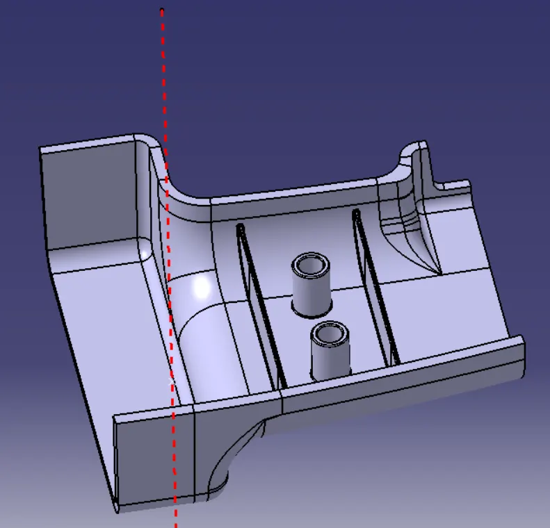
DRAFT ANALYSIS OF GIVEN CLASS A SURFACE
Check the draft analysis of the given class A surface along the tooling direction to ensure the part has minimum draft angle (3 degree) in all faces .Here the faces along Z-direction is not clearing the minimum draft . The tooling axis created in three methods (point and direction,bisecting and normal to face method ) and checked the draft analysis. The result is same so it conclude that class A surface not clearing the minimum draft angle 3 degree.
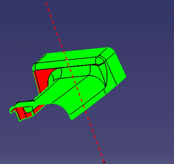
CLASS B SURFACE
Class b surface created from class A surface using extracting ,extrapolate,untrim and trim operation
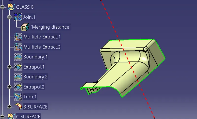
CLASS C SURFACE
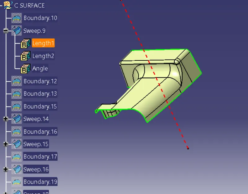
Class c surface created using the boundary of class A and sweep with reference surface operation .
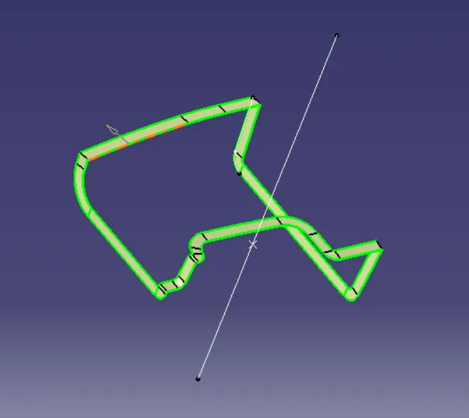
Then join the class A with class C surface and finally trim with class B surface to create the closed surfcae of handle part .
RIB DESIGN
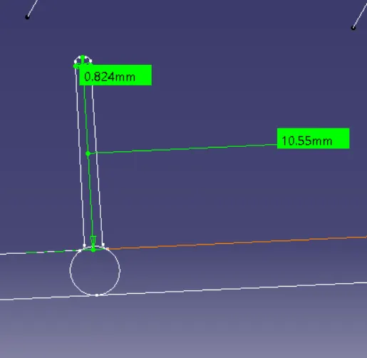
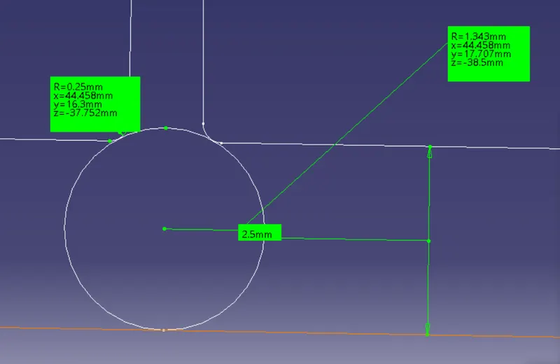
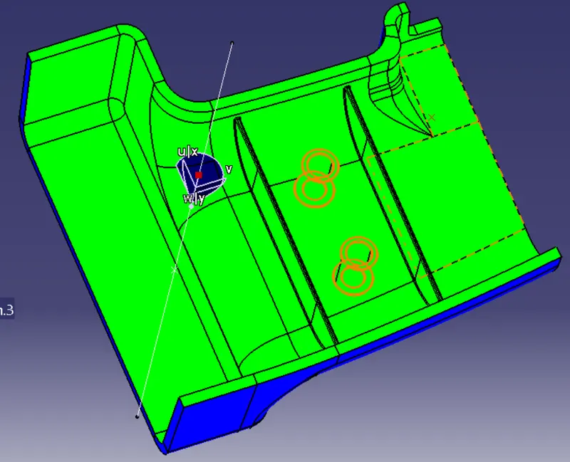
Rib created for the given hnadle part by folloing the design rules shown in fig
The rib thickness is 1 mm and the rib depth is 12.5mm (5*2.5).The rib root thickness is 2.68mm which is inside the limit.The maximum deviation is 30% of wall thicknes at the rib root area (2.5*1.3=3.25mm ).rib thicknes at the top is 0.78mm(>0.75mm).Hence the rib design following the design rules.
SCREW BOSS DESIGN
General Guidelines for Bosses:
- Draft - 0.5 degrees on the walls of boss
- Thickness - Typically 40%* of the nominal wall at the base.
- Height to Diameter Ratio - 3:1
Radii - 0.25mm maximum radii.
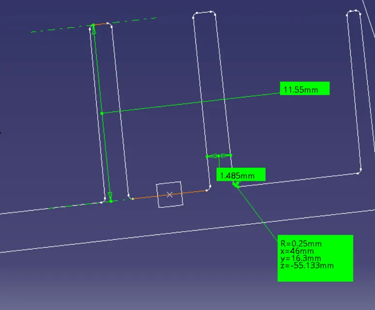
The screw boss thickness is 1.5 (0.6*2.5) and draft is provide 0.5 degree .The screw boss created by following the design rules.
DRAFT ANALYSIS OF RIB AND SCREW BOSS
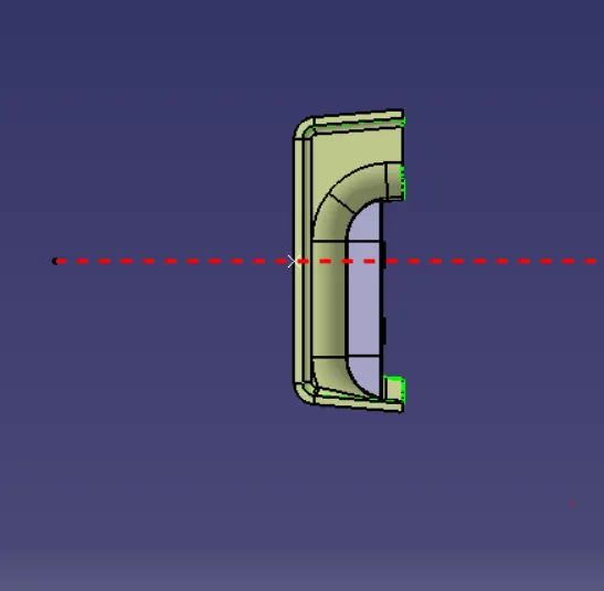
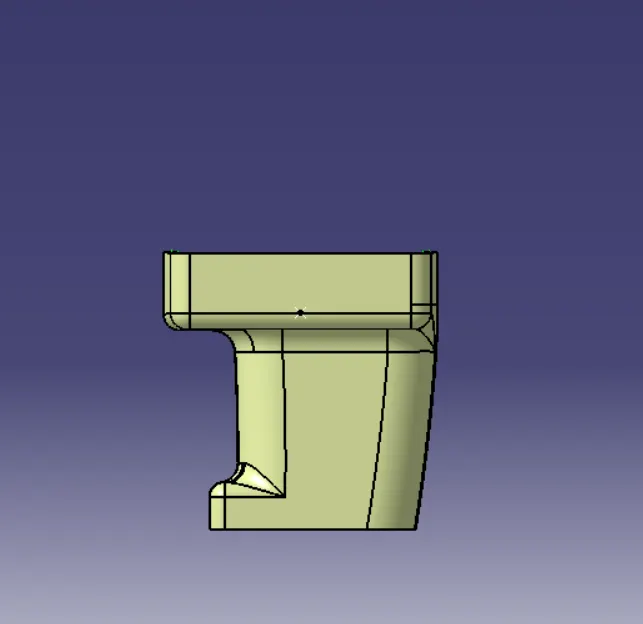
Checking the rib and screw boss has minimum draft of 0.5 degree on the wall. shown fig.
The screw boss and rib has minimum draft 0.45 along the tooling direction
CONCLUSION
The rib and screw boss created by considering the design rules.