Week 10 - Challenge 1- Attachment Feature Creation (Ribs & Screw Boss)
Aim:-
To create the Rib and Screw Boss for the Drill Handle considering the design rules from the given Class-A surface.
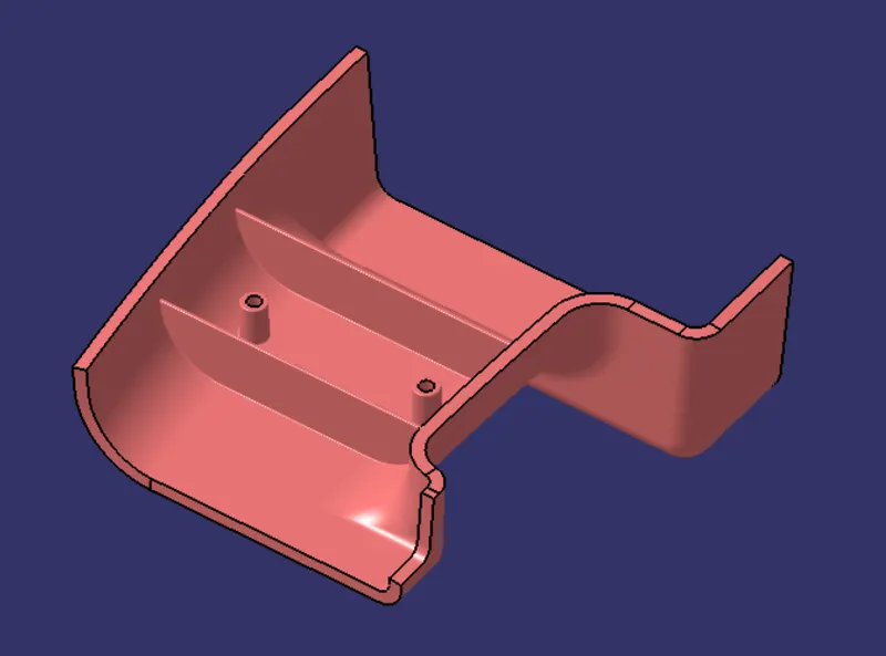
Fig.1: Drill Handle.
Tooling Axis:-
The direction with respect to the component in which the mould opens and closes is the tooling axis. Basically, it defines the direction in which the mould pulls apart.
Procedure to create the tooling axis:-
For this model,
- First, the given Class-A surface was observed carefully from every direction and found that in Y-direction the Tooling Axis can be created.
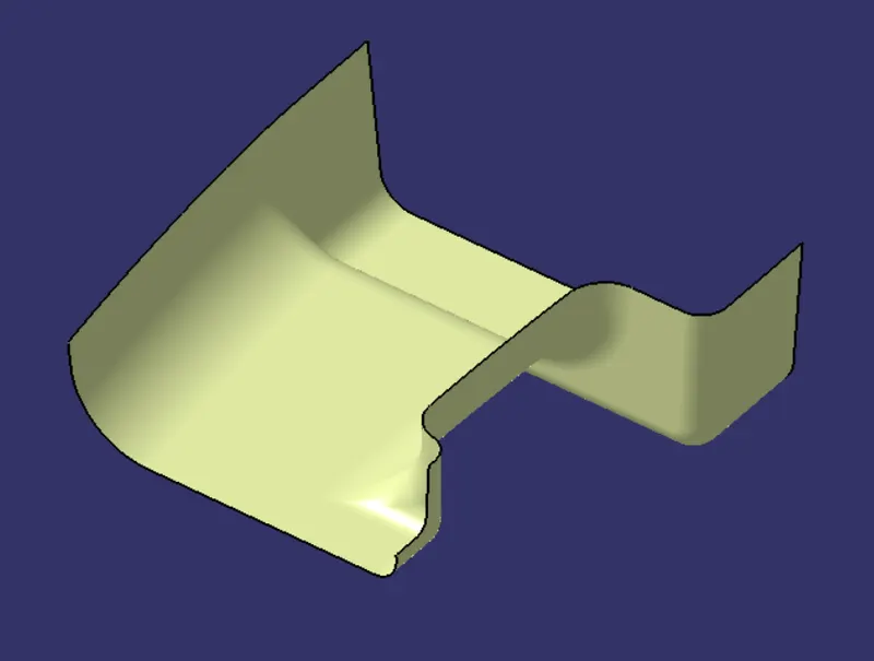
Fig.2: Given Class-A surface. - Then, one bottom surface was extracted and a point was created in the middle of that surface.
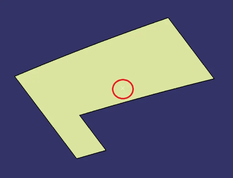
Fig.3: Point on the extracted surface. - Then, a line was created passing through that point along Y-Axis.
- Then, draft analysis was done for the Class-A surface considering the line as tooling direction.
- When no error was found in the draft analysis the line was named as Tooling Axis.
- Hence, the Tooling Axis was created.
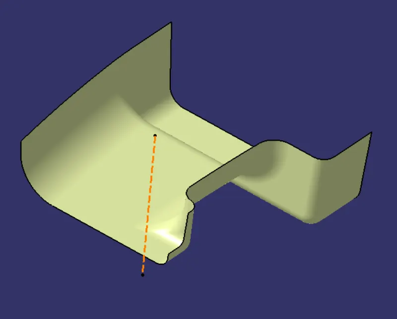
Fig.4: Tooling Axis.
Draft Analysis:-
The draft analysis is used to analyze whether our part model created in CAD is manufacturable based on the draft angle and the tooling direction provided. It also enables us to detect if the part will be easily removed from the mould or not. The ejection of the part from the mould depends on the draft angle.
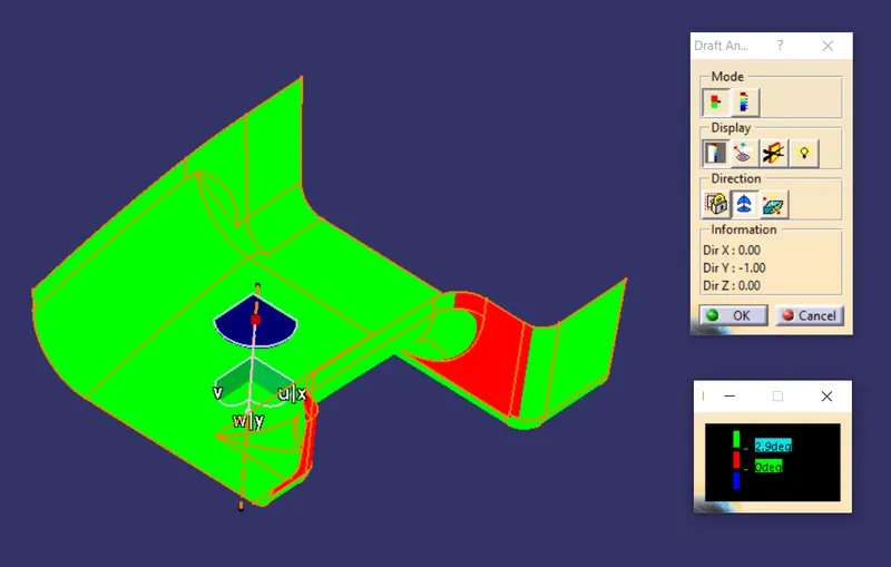
Fig.5: Draft analysis of the given Class-A Surface, considering the draft angle of 2.9 degrees.
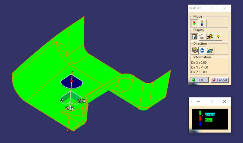
Fig.6: Draft analysis of the given Class-A Surface, considering the draft angle of 0.5 degrees.
Class-B Surface:-
Class-B Surface was created by offsetting the Class-A surface by 2.5 mm. Then the surface patches were solved.
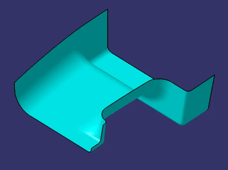
Fig.7: Class-B Surface.
Class-C Surface:-
Class-C Surface was created using the boundary of the class-A surface and sweeping it perpendicular to the class-A surface. Then the edges of the sweeps were extrapolated and trimmed with each other.
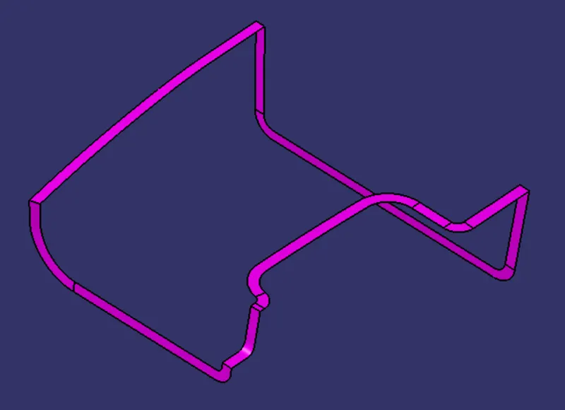
Fig.8: Class-C Surface.
Combining A, B and C Surface:-
All three surfaces were combined by joining the Class-A and Class-C surfaces and trimming them with the Class-B Surface. At last, it was converted into the Solid Model by using the Close Surface command.
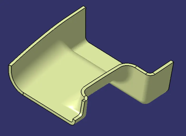
Fig.9: Joined Class-A, Class-B, and Class-C Surface.
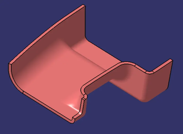
Fig.10: Solid Model.
Rib Design:-
After making solid model ribs were created following the rib design rules.
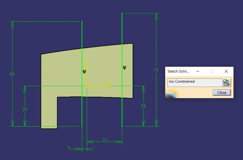
Fig.11: Sketch for ribs.
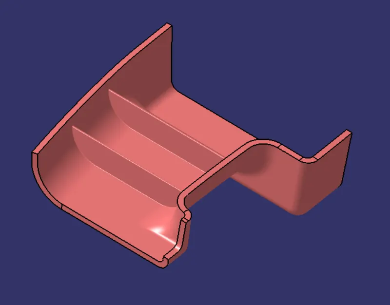
Fig.12: Model with ribs.
Screw Boss Design:-
At last Screw Bosses were created following the screw boss design rules.
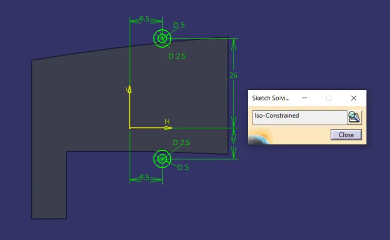
Fig.13: Sketch for Screw Bosses.
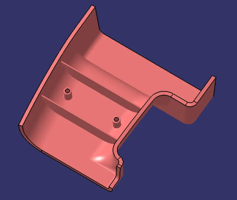
Fig.14: Model with screw boss.
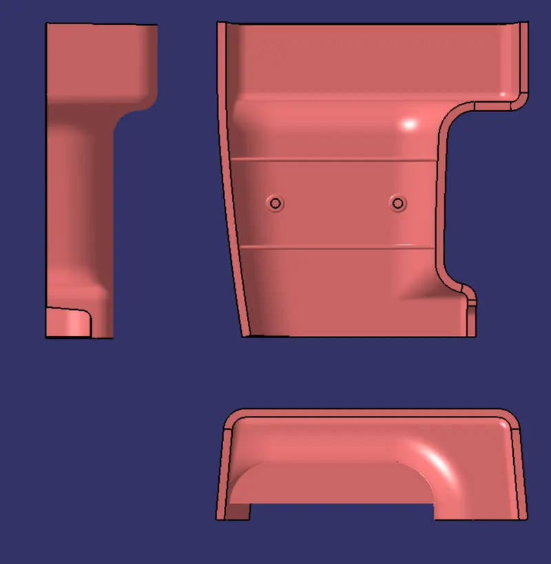
Fig.15: Different views of the Drill Handle.
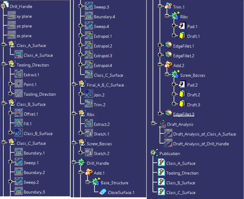
Fig.16: Tree Structure for the Geometrical Sets and the Part Body of the Model.
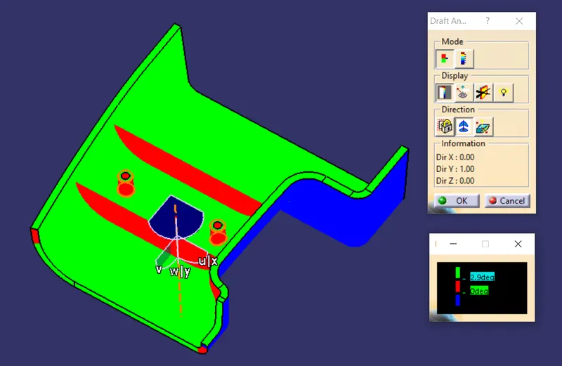
Fig.17: Draft analysis of the Drill Handle, considering the draft angle of 2.9 degrees.
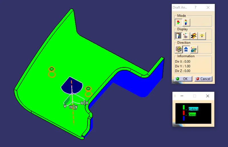
Fig.18: Draft analysis of the Drill Handle, considering the draft angle of 0.4 degrees.
Conclusion:-
The Rib and Screw Boss was created for the Drill Handle considering the design rules from the given Class-A surface. Also, the Tooling axis was created and perform the Draft analysis on both Class-A Surface and the solid model.