Week 10 - Challenge 1- Attachment Feature Creation (Ribs & Screw Boss)
STEPS
- Import the given A surface to the CATIA V5.
- After importing insert a geometric set for A surface
- Then insert a new geometrical set for Tooling axis.
- With the tooling axis created check the Draft analysis.
- Then Create B surface in New geometrical set by offseting by 2.5mm.
- Correct the mistakes in B surface bt extracting, extrapolating, trim and by multi-section surface.
- After creating B surface insert new Geometrical set and name it as C surface
- For Creating C surface create bountary in A surfaces.
- Then Sweep the bountary by Using With draft Direction tool ande select tooling axis as direction
- Give 3degree draft.
- Then create A+C surface and then Trim A surface and C surface.
- Create Final Trim Geometrical set and trim A+C surface with B surface.
- After getting final trim then create a body.
- Change work bench into part design and create close cody.
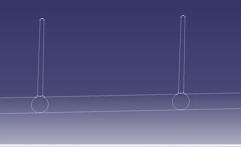
- Create a point on B surface where you want to create heat stake.
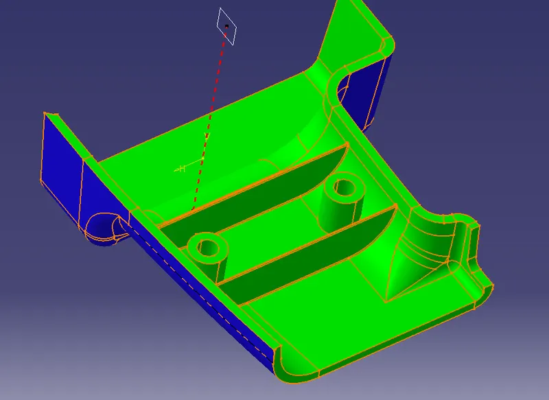
- By the given dimension Create Heat stake .
- Give Draft angle of 0.5degree
- Create a new body for creating RIB.
- create rib and draft it and give fillet as in the question .
- Union trin the Heat stake and Ribs with the main body.
- Check the Draft analysis and confirm it.