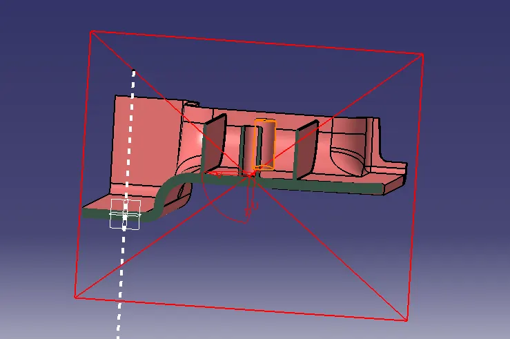
Week 10 - Challenge 1- Attachment Feature Creation (Ribs & Screw Boss)
CREATING TOOLING AXIS.
- First, we create a plane on the surface. Then draw two lines based on the projection of class A or using the intersection of the point’s method.
- Now Using the Bisecting method, select the two projected lines and get the Tooling axis.
DRAFT ANALYSIS OF SURFACE A
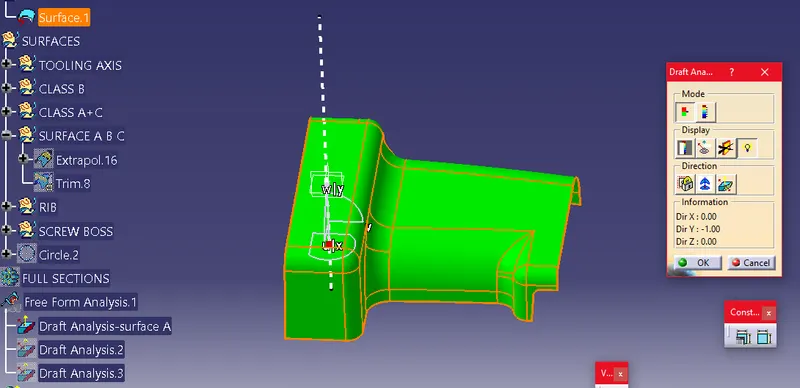
CREATING CLASS B AND CLASS C SURFACES.
- Then I created the Class B surface, Using the following commands.
Offset.
Trim.
Multi-surface.
Boundary.
Split.
Join.
Untrim.
Extract.
Multi-Extract.
- Then I created the Class C surface, Using the following commands.
Sweep.
Boundary.
Smooth- Surface.
Multi-Extract.
- After creating the Class B and Class C Surface, I Joined the Surface A and Surface C and Trimmed them with Surface B.
Join A+C.
Trim A+C-B.
SURFACE B
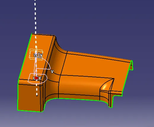
SURFACE A + C
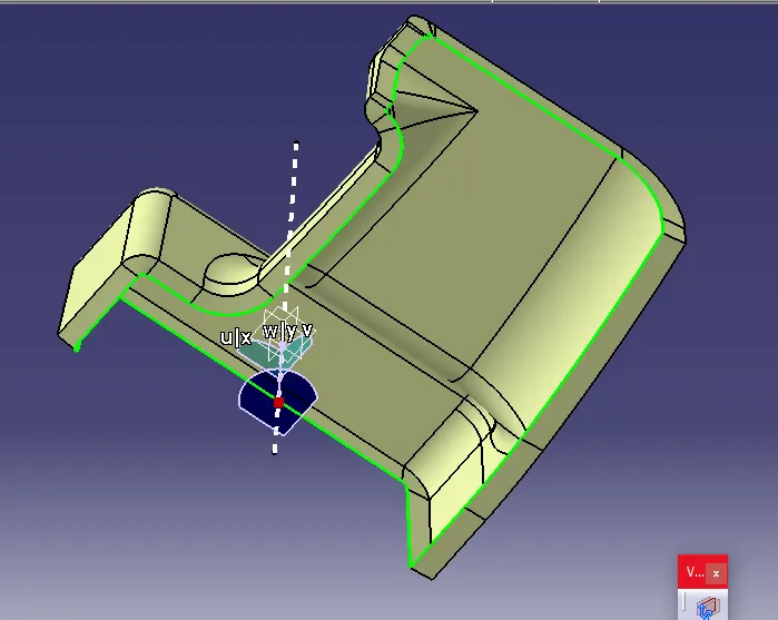
SURFACE A + B + C
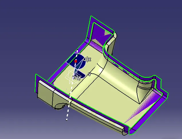
- After creating the Closed Surface, I checked for the closed surface using the Boundary Condition.
FINAL SURFACE
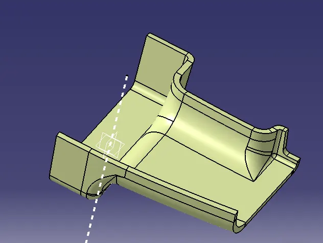
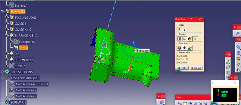
DRAFT ANALYSIS OF CLOSED SURFACE.
- After creating the closed surface, I checked for the draft analysis by clicking insert-->Analysis-->Draft analysis.
- And My Closed surface passed the draft analysis test.
CREATING RIBS AND SCREW BOSSES ON THE SURFACES.
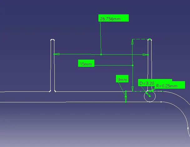
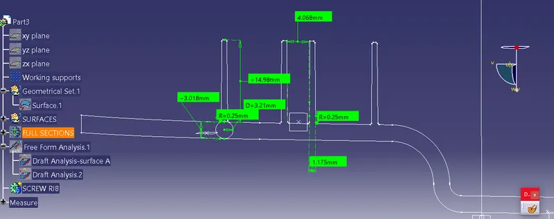
Now I create the Ribs and Screw Bosses on the surfaces based on the design rules given and draft analysis also taken for the surfaces.
DRAFT ANALYSIS OF PRODUCT WITH RIB AND SCREW BOSS.
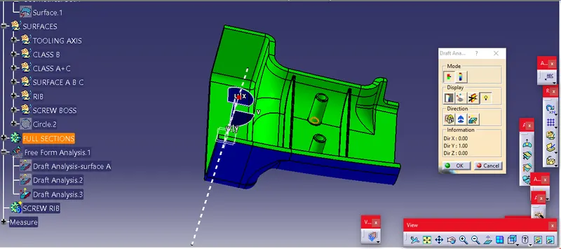
RIB ANALYSIS AT INTERSECTION 1
SCREW BOSS AND RIB- INTERSECTION 2
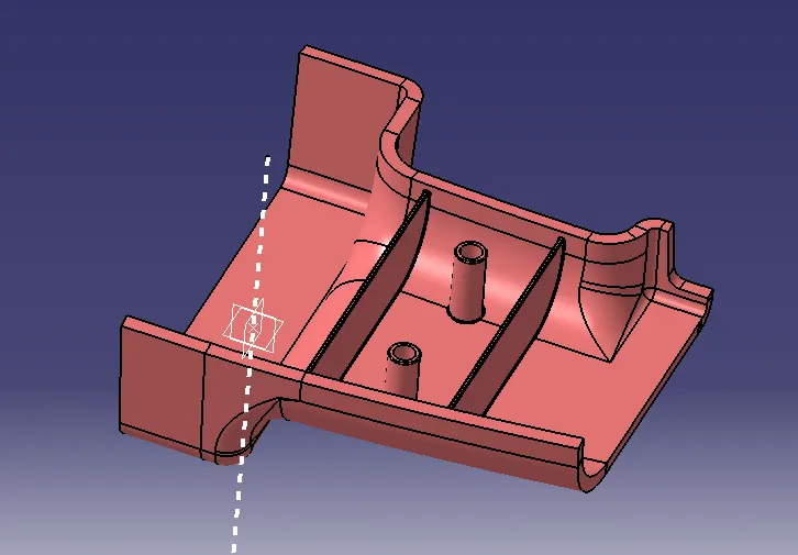
SAVING CLOSED SURFACES AS A PART.
FINAL PART
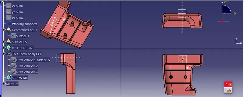
DIFFERENT VIEWS
CROSS SECTIONS