Week 10 - Challenge 1- Attachment Feature Creation (Ribs & Screw Boss)
Attachment Feature Creation (Ribs & Screw Boss)
OBJECTIVE:
- Create the rib for the Drill Handle considering the design rules
- Create the Screw boss for the Drill Handle considering the design rules
- A detailed report should be done explaining the draft analysis and the tooling axis creation.
REPORT:-
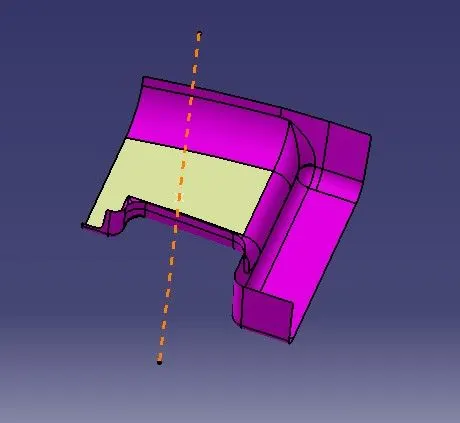
TOOLING AXIS
Tooling axis is the direction in which mold or core and cavity opens. The ejection of the part from mold depends on the draft. A zero draft can result in difficult or no ejection due to shrinkage. It is recommended to add a minimum of 0.5 to 1 degree of the draft for non-textured surface & 3 to 5 degree of draft for textured surfaces.
Steps used to create tooling axis for the given Class-A Surface
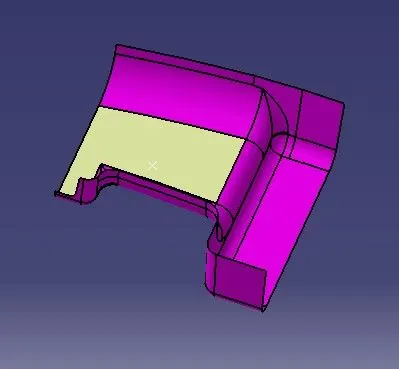
- Extract the surface from Class A surface by using extract command and create a point in it.
2. Define the tooling axis in y direction.
SURFACES
CLASS A SURFACE
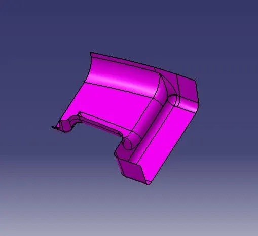
It gives the aesthetic of the component which is created by the styling team and gives to the part design engineer to create the part with all engineering aspects.
CLASS B SURFACE
Class B surface is created by Offseting the class-A surface to 3mm inward direction. The patches are created while offsetting the surface. Rework on the patches using the features like extract, multi-extract, sweep, multi-section surfaces, extrapolate.
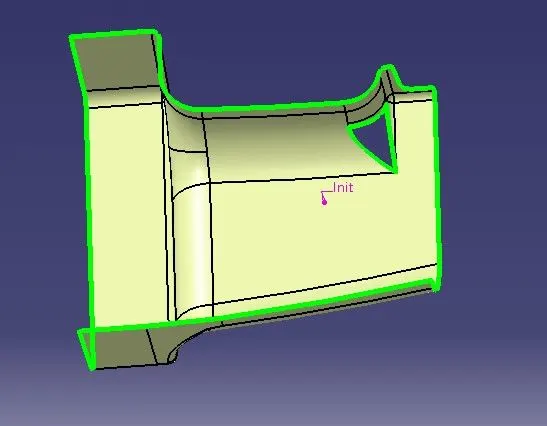
CLASS B SURFACE IS CREATED
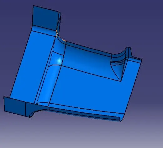
CLASS C SURFACE
The surface that joins class-A and class-B surfaces are class-C surfaces. Class C is often specified for interior surfaces not readily visible, surfaces that will be covered by another part when assembledThe Class C finish allows more imperfections than Class A or B. Class C is often specified for interior surfaces not readily visible, surfaces that will be covered by another part when assembled, or surfaces which the Customer feels do not need to meet a high cosmetic finish.
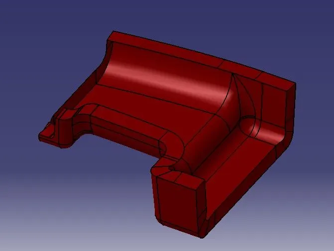
CLASS B is trimmed with CLASS A AND C
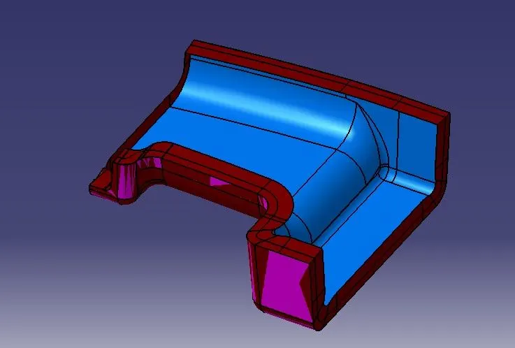
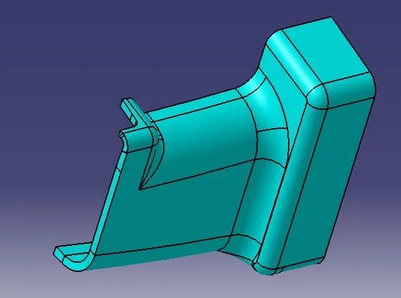
SOLID BODY
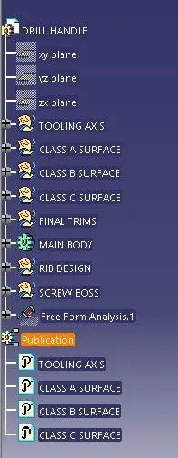
TREE STRUCTURE
RIB DESIGN
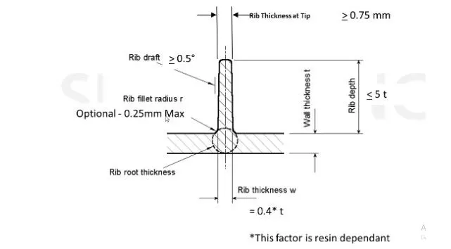
DESIGN RULE FOR RIB CREATION
Sketch for rib creation
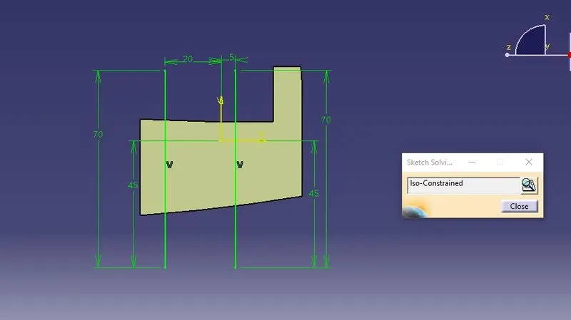
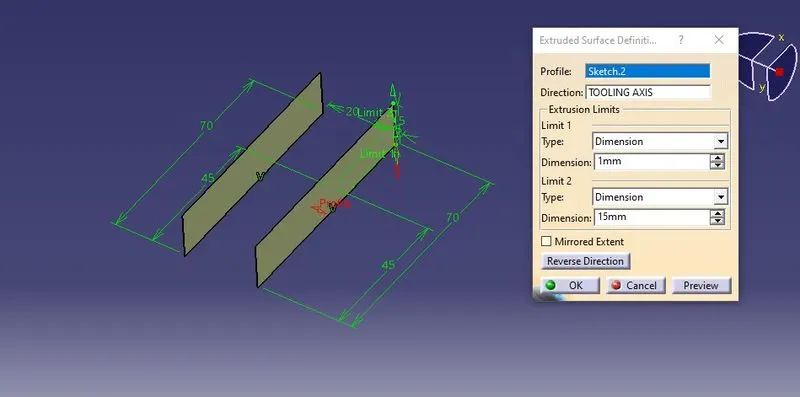
Extruded and created the surface according to the height of ribs in design rules
height - <=5t (thickness of part)
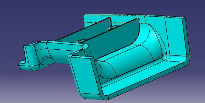
Part is timmed with main component
DESIGN RULE FOR SCREW BOSS CREATION
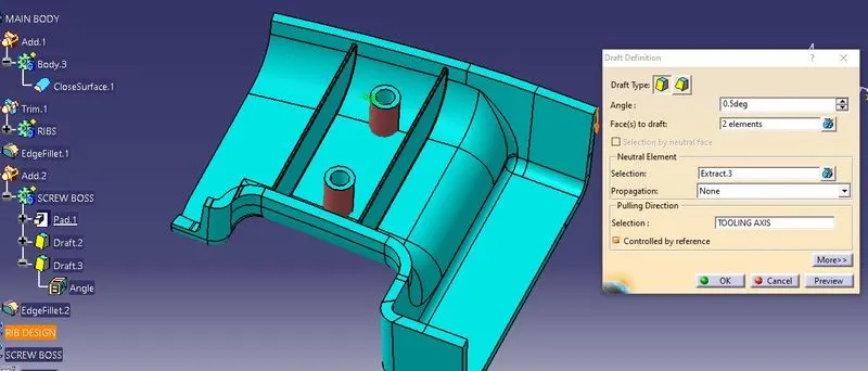
- Draft - 0.5 degrees on the walls of boss
- Thickness - Typically 40%* of the nominal wall at the base.
- Height to Diameter Ratio - 3:1
- Radii - 0.25mm maximum radii.
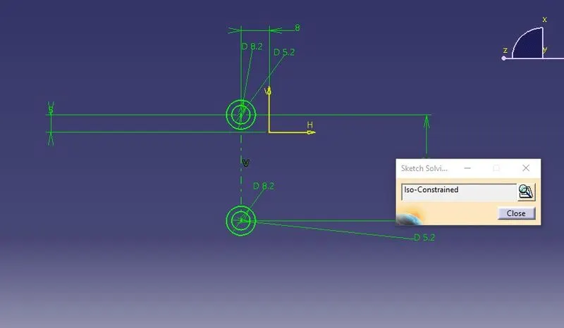
Sketch is created the diameter taken (m6 bolt) 5.2mm
paded the sketch for height
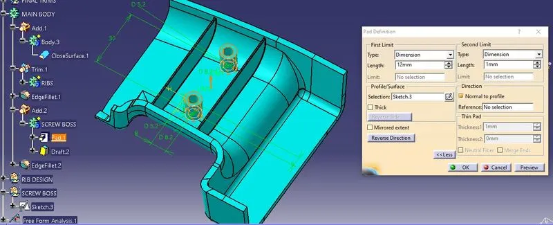
draft direction of inner and outer walls is opposite
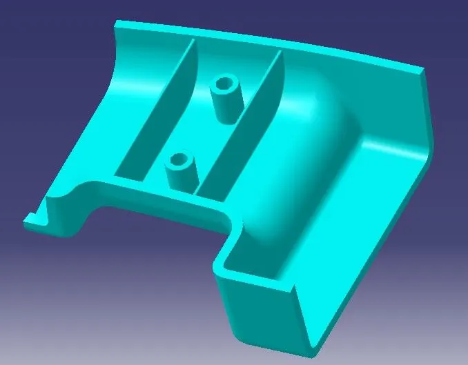
FINAL COMPONENT
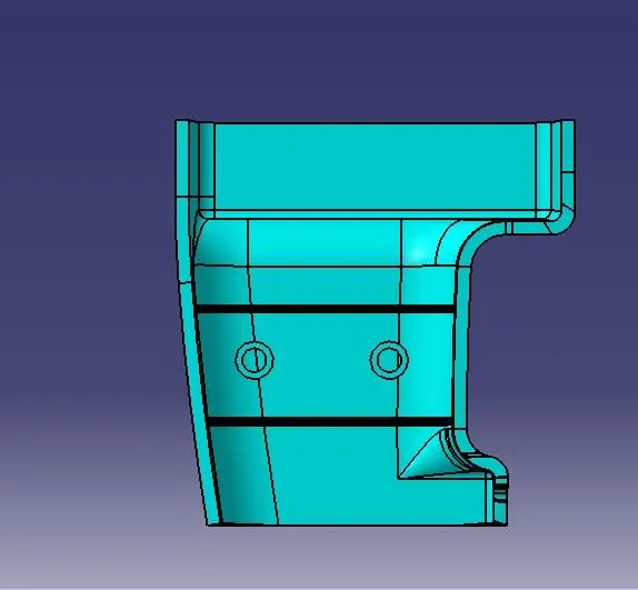
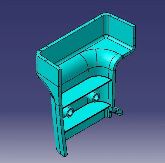
DRAFT ANALYSIS
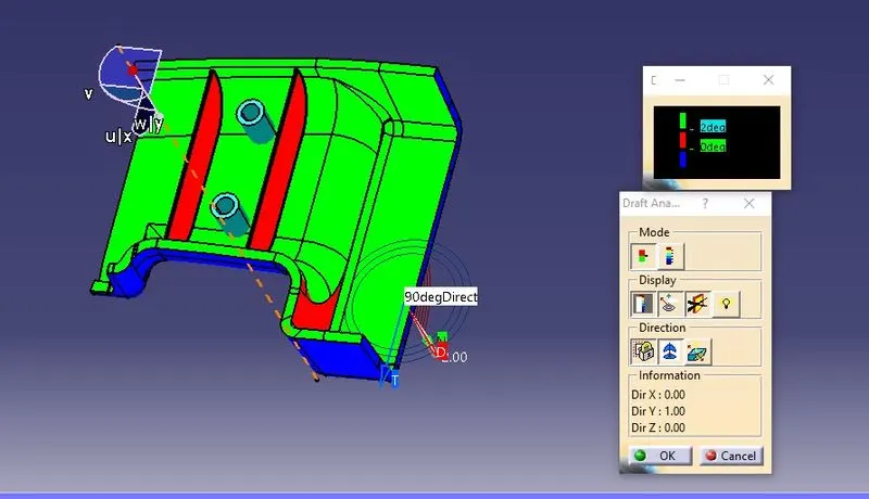
Draft analysis is performed based on color ranges identifying zones on the analyzed element where the deviation from the draft direction at any point, corresponds to specified values. Minimum draft angle is considered as 3 degree.
- Screenshots of the Draft analysis report for both the given Class-A surface and the final plastic component.
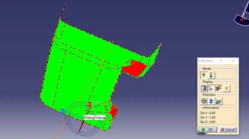
DRAFT ANALYSIS OF FINAL COMPONENT