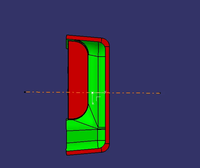
Week 10 - Challenge 1- Attachment Feature Creation (Ribs & Screw Boss)
RIB:
Ribs are created to provide additional strength and stiffenes to the solid model without affecting the thickness of the product. In addition to that in some designs ribs are also used as stoppers.
Design considerations on Rib:
- Draft need to be 0.5 deg
- Height of the rib 5 times the thickness (t)of the base
- The nominal thickness of the rib is 40% - 50% of the thickness (t)of the base
- Top end thickness should be greater than or equal to 0.75mm
- Fillet radius can be 0.25mm as minimum
- Spacing between ribs are 2:1 or 3:1 with height to thickness of base
SCREW BOSS:
Screw boss are to provide strength to the holes and screw the fasterners easily free-off using instruments.
Design considerations of Screw boss:
- Draft angle = 0.5deg
- Width of the screw boss is 60% of the thickness of the base
- Fillet radius =0.25mm as minimum
Door Handle component Design:
Door handle to be created with ribs and screw boss.
First check the surface of the given class A surface whether any discontinuties. Then to do draft analysis on the class A surface.
DRAFT ANALYSIS:
Draft is defined as providing a taper angle to the core and cavity , mould model . It is provided to ease ejection of the moulded product from the core cavity without any wear , damages alon walls cause due to friction. So it is important to give draft angle to the part body.
Draft analysis is done to ensure whether the draft provided product is feasible for manufacture.
TOOLING AXIS:
The draft analysis can be done only with the tooling direction, so creation of tooling axis is also important.
The surfaces of the component is more visible on y direction.
Creation of Tooling axis:
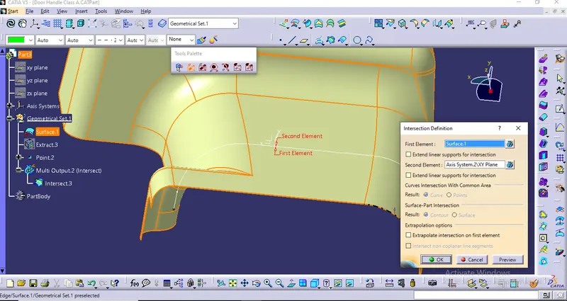
Intersect the surface along xy and yz planes and craete each lines along each planes. and by bisectingg these two ines we have the tooling axis.
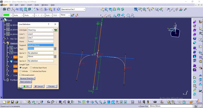
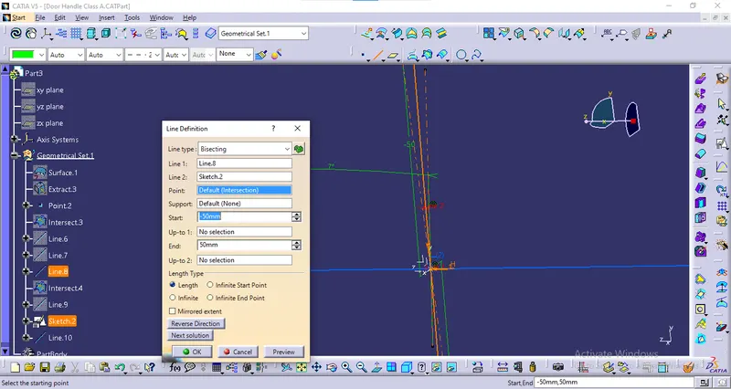
Draft analysis on class A surface:
The draft of the surface is identidied using color variants. The minium draft angle for the component is 3deg.
color code:Green - more than 3 deg
Red - between 0 - 3 deg
Blue - less than 0 deg or inverse deg
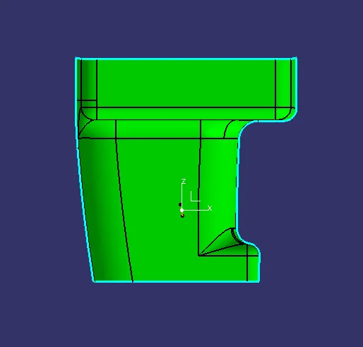
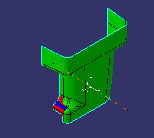
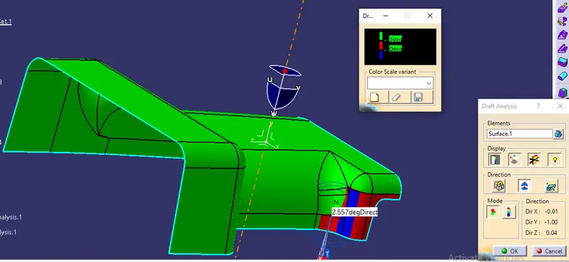
We can also find the draft angle at particular point by using the "running command" .
Creation of solid close surface:
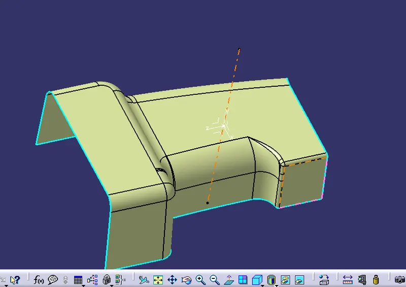
Create class B surface from the input class A surface , the class A is the aesthitic surface received from the styling team. Class B is the surface in whichh engineering works are done . The thicknesss of the component is 3mm .
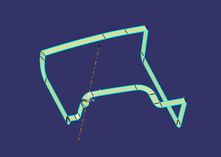
Class C surface is the joining surfaces of class A with Class B.
CREATION OF RIB and SCREW BOSS:
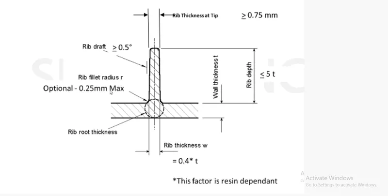
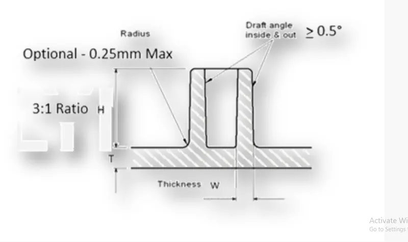
height = 5*t= 15mm , whereas thickness t=3mm
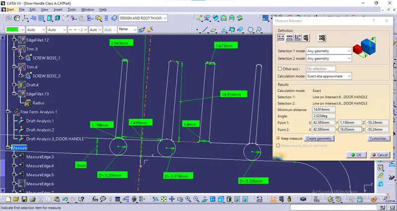
nominal width of rib = 0.4*t = 1.2mm
The two ribs are created with spacing of 23.8mm considering the position of the srew boss between the ribs.
Gap between rib= 2:1 = h:t
=15/2=7.5mm
Width thickness of screw boss = 0.6*t = 1.8mm
ROOT THICKNESS:
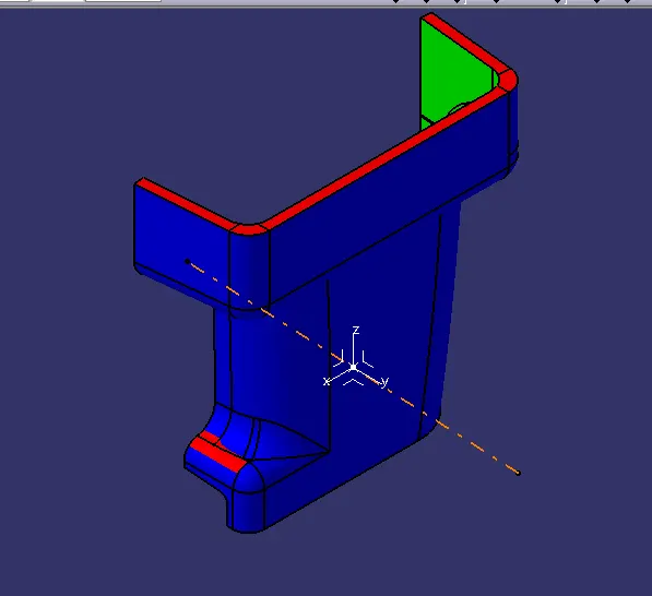
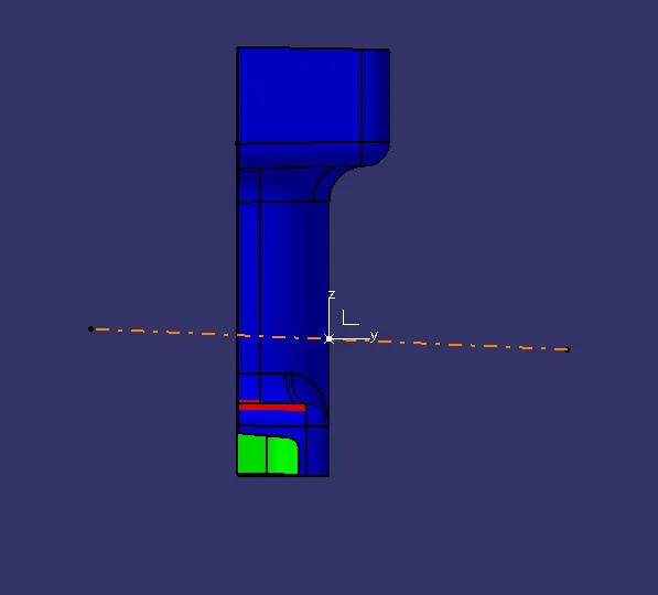
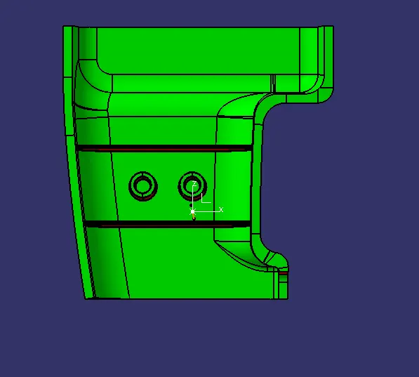
DRAFT ANALYSIS ON FINAL MODEL:
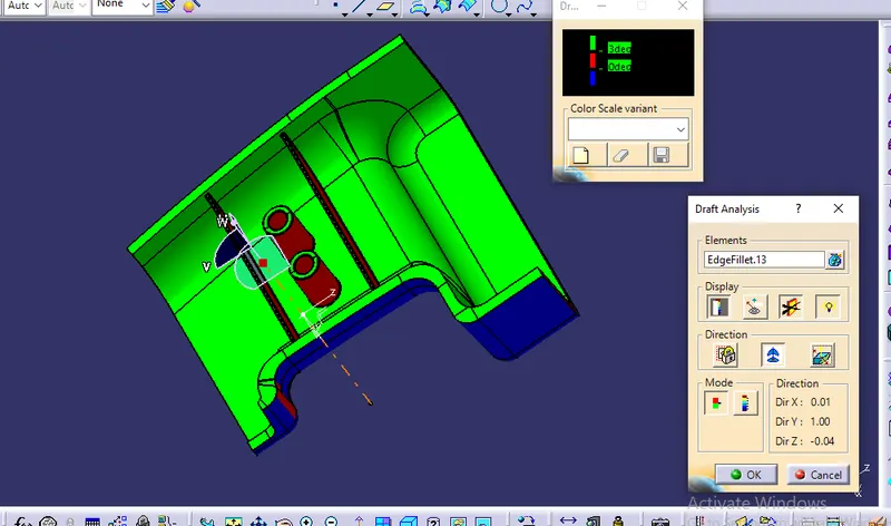
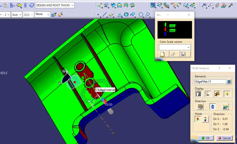
color variant ; Green - more than 3 deg
Red - between 0 to 3 deg
Blue - less than 3 deg and inverse direction
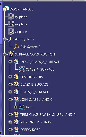
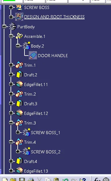
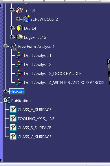
TREE STRUCTURE:
ISOMETRIC VIEWS:
FRONT VIEW:
SIDE VIEW:
TOP VIEW: