Week 10 - Challenge 1- Attachment Feature Creation (Ribs & Screw Boss)
AIM: Create a RIB and SCREW BOSSES for the Dril Handle considering all designing rule.
Objective: In this project i'm going to create rib and screw bosses on Door Handle using the different tools in CATIA V5 software. Use positioned sketch and this sketch should be ISO constrainted. Also perform draft analysis.
General guidelines for RIB
- Draft should be equal to or greater than 0.5 degree
- Hight/Depth of the rib is greater than or equal to 5*t (Where t is thickness of the Door Handle wall)
- Thickness (t) of the Door Handle wall
- Optimal fillet should be 0.25mm maximum
- Ribroot must be greater than thickness of the Door Handle and optimal value 0.25 max
- Buttom rib thickness should be 0.4*t
- Upper rib thickness should be greater than or equal to 0.75mm
- Distance between two rib should be greater than 2:1 ratio and less than or equal to 3:1 ratio.
General guidelines for SCREW BOSSES
- Draft - 0.5 degrees on the walls of boss
- Thickness - Typically 40%* of the nominal wall at the base.
- Height to Diameter Ratio - 3:1
- Radii - 0.25mm maximum radii.
RIB DESIGN
Begore going on to the rib design we will have to create close surface of given input class A surface.
TOOLING AXIS:
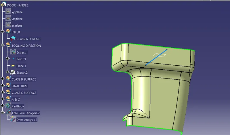
First we have to observe and study the class A surface to create the "Tooling Axis" for the component, and for the above given door handle. Here i use bisecting method to create tooling axis by the use of side wall surface. Initially, I create a dummy tooling axis on y-axis by considering the reference point created on the any curve of the door handle. When we create axis on door handle through bisecting method, the axis coinside with the dummy axis but first we have to check class A surface making an angle direction inbetween 0-3 degree by draft analysis method.
DRAFT ANALYSIS:
To perform draft analysis, click on Insert>Analysis>Feature Draft Analysis
Once the draft analysis toolbar is opened, go to the display block and select the 'Analysis under the running point' command to check the angle for different sides (walls and inclined plane angles) on the class A surface. The color scale on the bottom visualizes, whether the draft angle meets the requirements or not (3 deg) by indicating the colors Green, Blue and Red. Once the draft angle analysis was done, we need to align and fix the compass to the tooling axis of the class A surface.
To align and fix the compass to the tooling axis, go to the Direction block in the draft analysis toolbar and click on the 'Use the compass to define the new current draft direction option (or just click on the compass symbol). Now bring the compass to the surface and align it to the tooling axis of the class A surface and click on the lock symbol beside the compass in the direction block. Once we click on 'ok' on the draft analysis toolbar, we can finish the draft analysis process.
NOTE: First check shading is in material mode (Go to the customise view parameter)
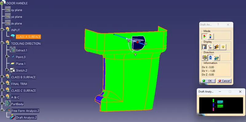
We can clearly see in the above figure draft angle is set to be 3 degree and all the surfaces are in green color it means we can consider tooling axis is now main tooling axis. But also it shows in blue color which is zero degree.
CLASS B SURFACE:
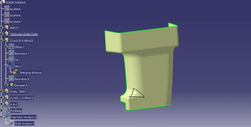
To create te class-B surfeace, I will go through the direct offset method becouse here the given door handle surface are very difficult to find out where to start class-B surface so to do that we have to directly offset it upto desired thickness and then we will go through, like some part are missing in offset surface. So that surface we have to fill by using extraction, untrimmed, extrapolation, trimming, joinning tool in surface design workbench etc.
Here it showing warning that some element or patches are missing so we have to click "OK".
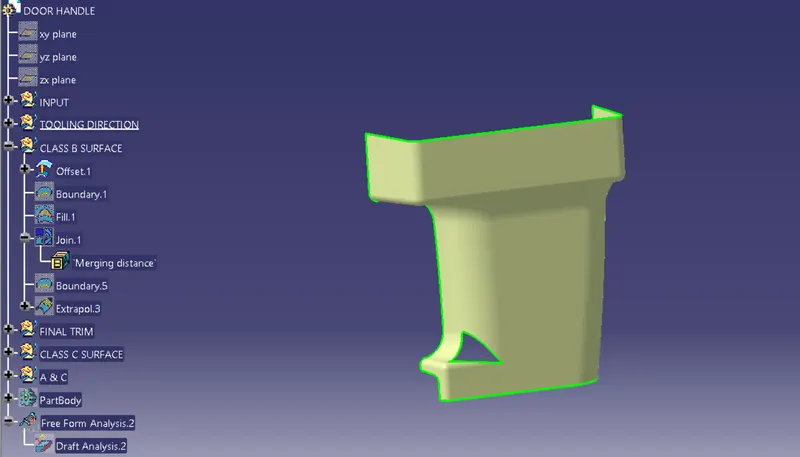
Use fill command to fill this empty surface
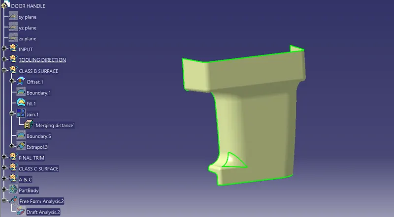
Now extrapolate this whole surface to trim with combined class A & C.
CLASS C SURFACE
It is the combination of Class A, Class B and Class C surfaces. To create a class C surface, I used the sweep command by considering the outer boundary of the class A surface. In the sweep command, go to the 'line' command in the 'profile' block and the subtype is 'with draft direction'. Now select the outer boundary and tooling axis, give 90 deg in the angle and select the direction to sweep, in this condition the class B surface is under the class A surface so select the inside down arrow to sweep. Now I joined all the sweeped surfaces by using the 'join' command and then I trimmed the Class A, Class B and Class C surfaces to make a closed surface, to make a Solid body.
Boundary creation and Sweep command:
Here we use one by one sweep and boundry command becouse there is sharp edge in the class A.
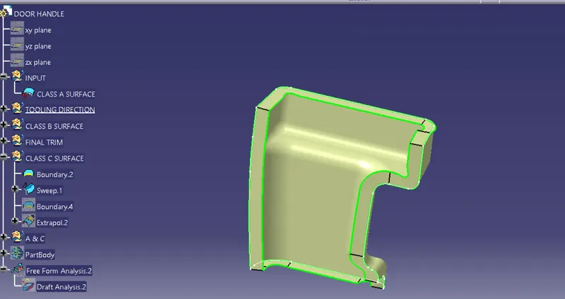
Join with class A surface
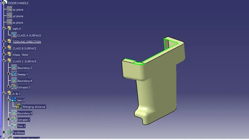
Now we can see that after joining boundry not created properly so we have to extrapolate and then trim it
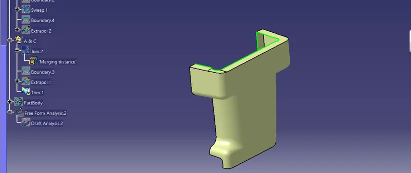
FINAL TRIM with Joined Class A & C
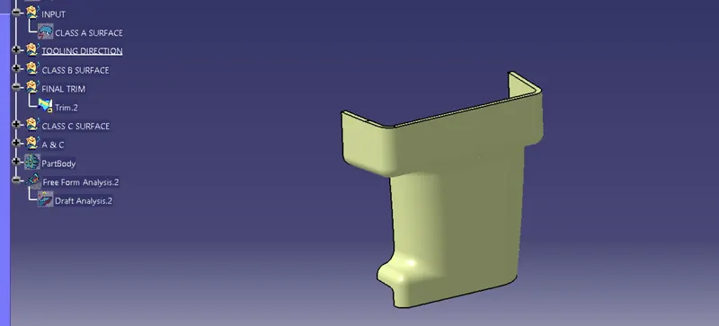
Now we have to check boundry of final trim, for checking final surface is in close or not
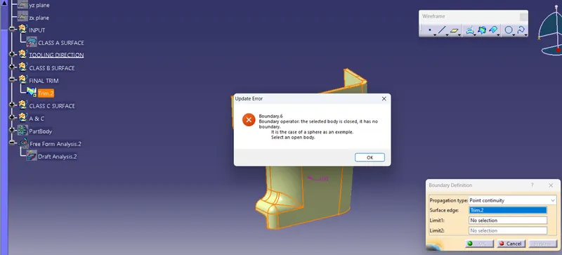
Now make it solid
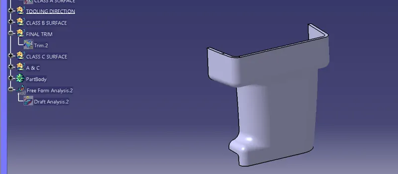
Now we have create RIB on solid body
So for RIB Design, first we have to study about where to create rib like here we have to create rib on b-surface so extract b surface and then create point on that surface where we want to create rib and then draw sketch, extrude it upto desired lengh like if the thickness of the solid body is about 2.5mm so we have to give hight less than or equal to 5t (t = thickness of wall)
Extract b-surface
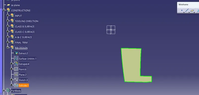
Untrim and then extrapolate
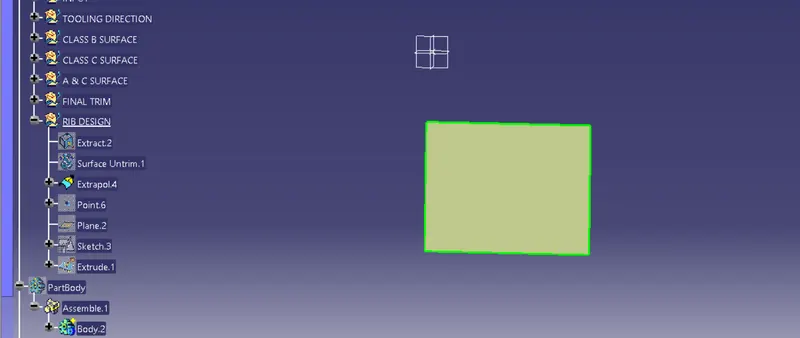
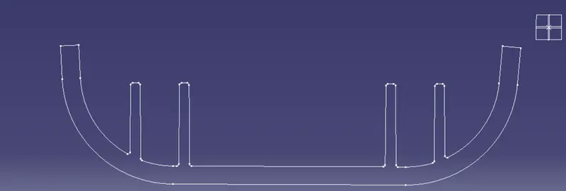
Sketch for rib design
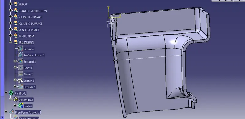
Extrude it upto 5*t = 12.5mm
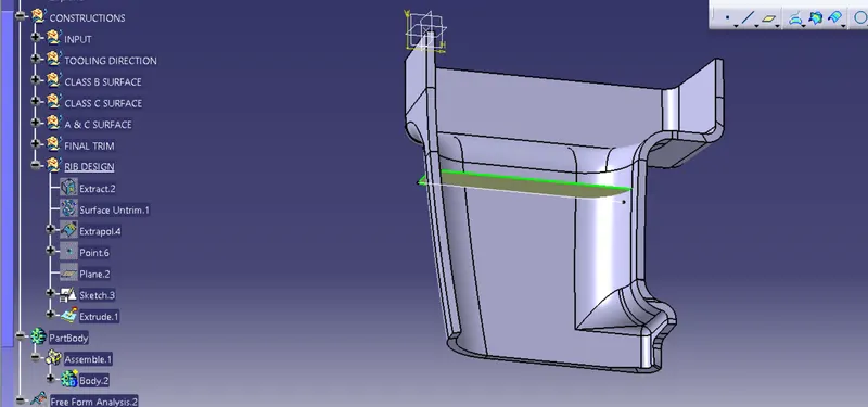
Thicken it in a new body upto 1mm according to guidelines (0.4*t)
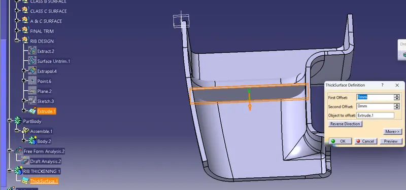
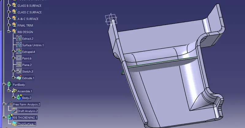
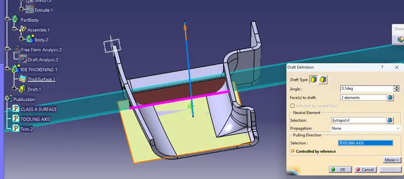
Draft it about 0.5mm from wall side
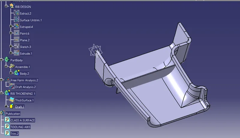
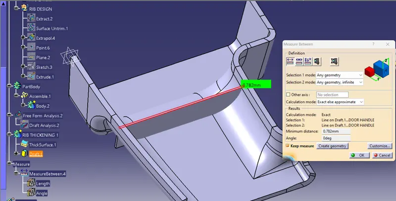
Upper side rib flatness should be greater than or equal to 0.75mm and here is approx 0.78mm
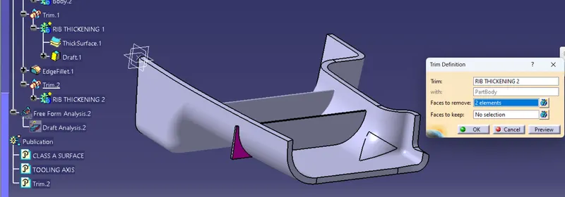
Now give union trim
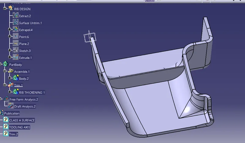
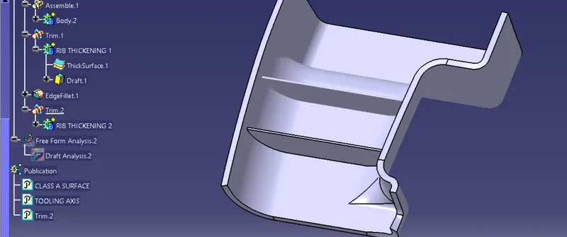
Now edge fillet 0.25mm
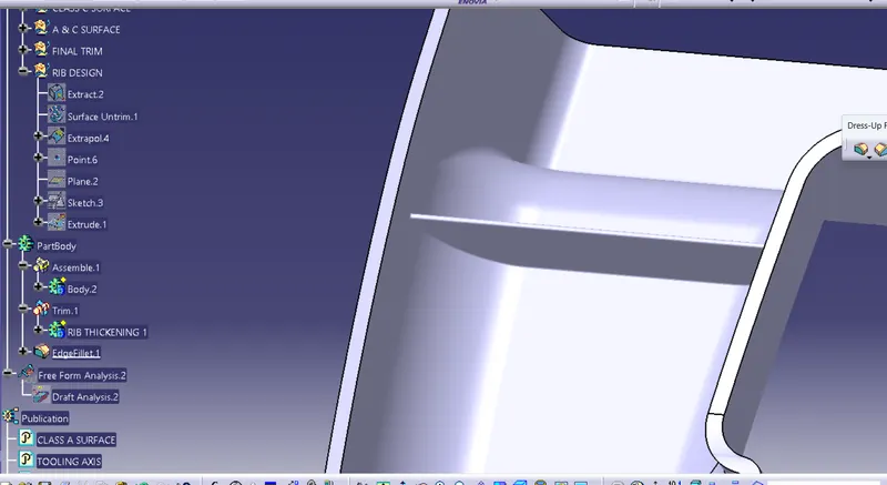
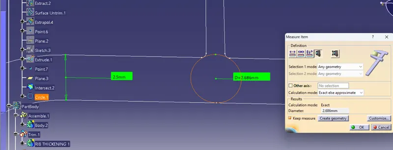
RIBROOT (ribroot circle dia is greater than 2.5mm thickness of the wall)
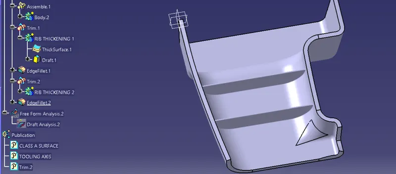
Now we have to create RIB 2 like rib 2 is not the offset of rib 1 sketch so we give the some distance and then by the use of copy paste method we translate solid rib 1 to rib 2
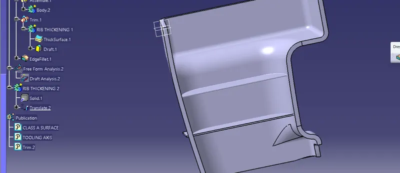
Give union trim and then give edge fillet
BOSS DESIGN
For the boss design,
- Create point and axis
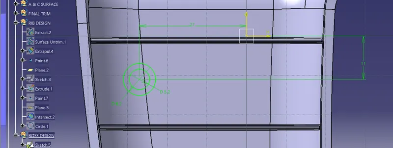
- Draw a sketch
- Pad it but less than rib hight
- Draft (greater than or equal to 0.5 deg)
- Add to the part body and
- Give fillet
Sketch
Padd it
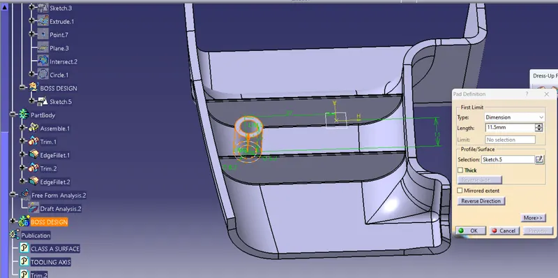
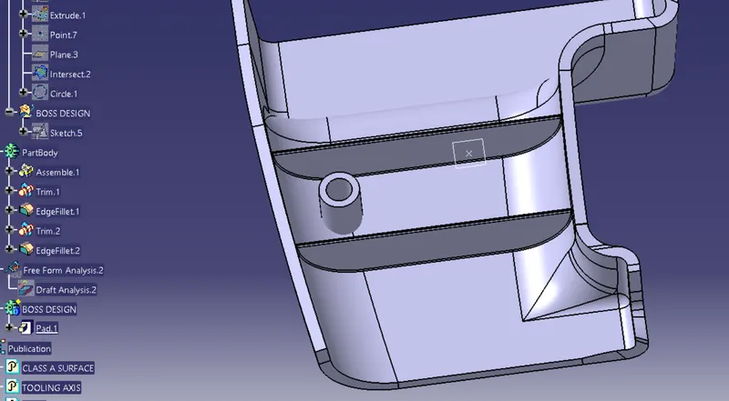
Give draft 0.5 degree
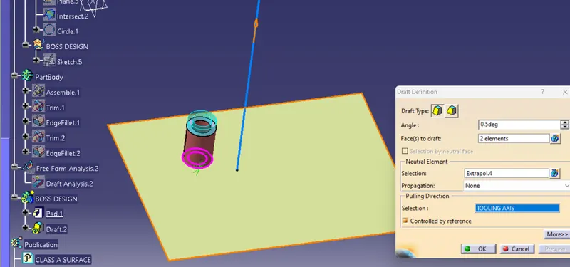
Add it in partbody and give edge fillet
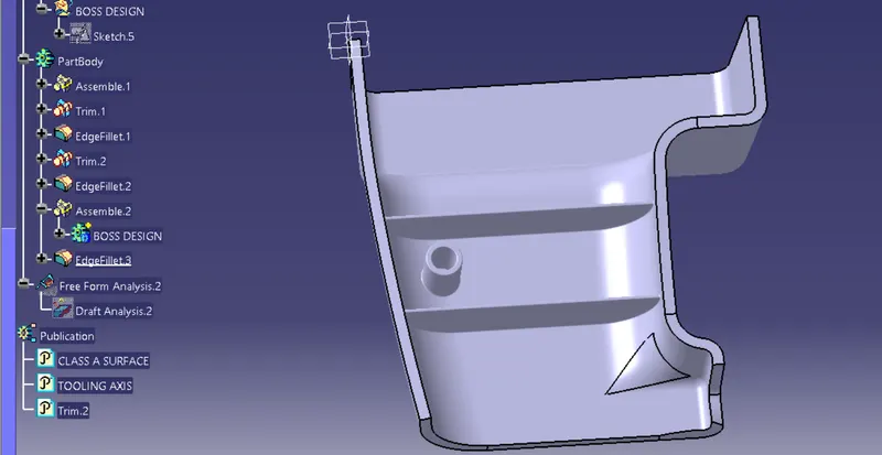
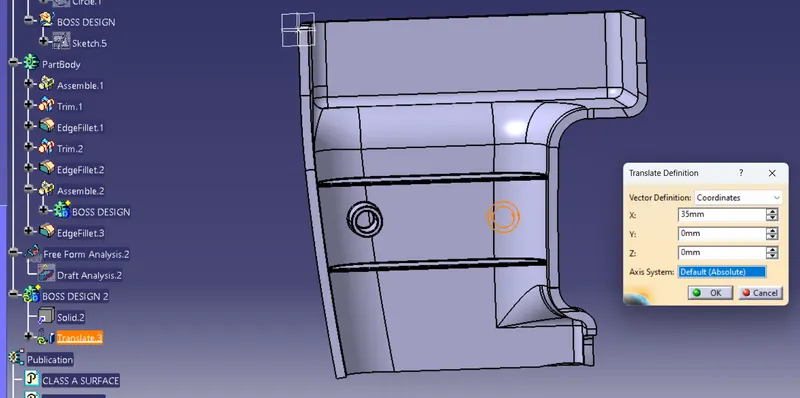
Now BOSS 2 by using copy paste and then translate it
Add this to part design and then give edge fillet
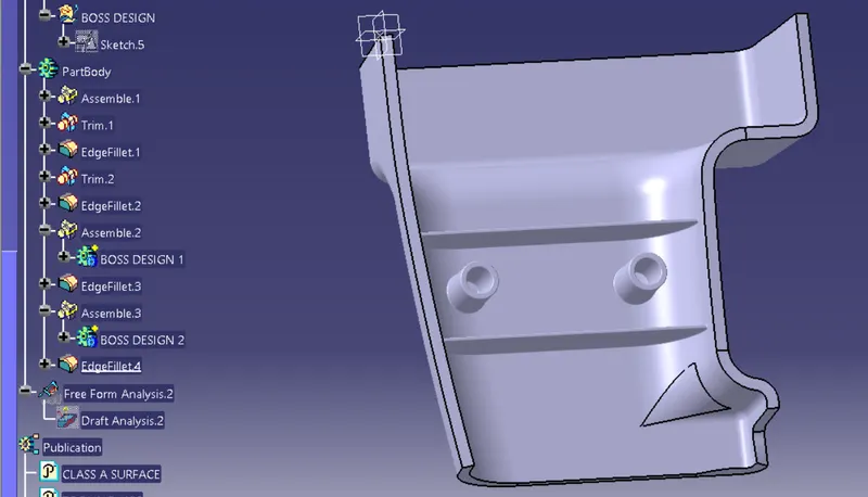
Check intersecion along with bosses
DRAFT ANALYSIS
To perform draft analysis, click on Insert>Analysis>Feature Draft Analysis
Once the draft analysis toolbar is opened, go to the display block and select the 'Analysis under the running point' command to check the angle for different sides (walls and inclined plane angles) on the class A surface. The color scale on the bottom visualizes, whether the draft angle meets the requirements or not (3 deg) by indicating the colors Green, Blue and Red. Once the draft angle analysis was done, we need to align and fix the compass to the tooling axis of the class A surface.
To align and fix the compass to the tooling axis, go to the Direction block in the draft analysis toolbar and click on the 'Use the compass to define the new current draft direction option (or just click on the compass symbol). Now bring the compass to the surface and align it to the tooling axis of the class A surface and click on the lock symbol beside the compass in the direction block. Once we click on 'ok' on the draft analysis toolbar, we can finish the draft analysis process.
NOTE: First check shading is in material mode (Go to the customise view parameter)
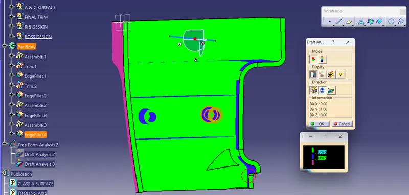
We can clearly see in the above figure draft angle is set to be 3 degree and all the surfaces are in green color but in some surface there is blue color also becouse of parallel to the tooling axis where blue color shows that 0 deg angle inbetween them.
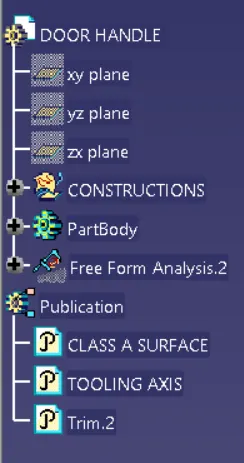
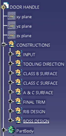
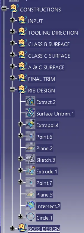
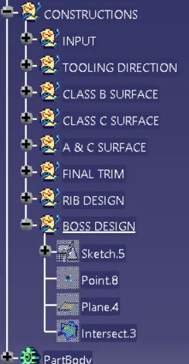
TREE STRUCTURE:
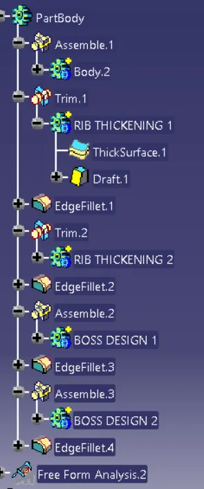
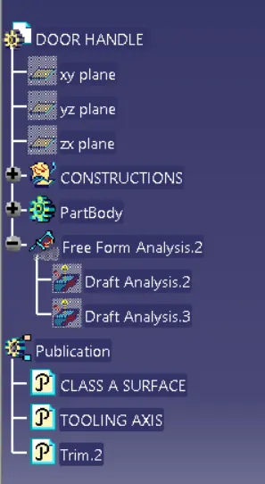
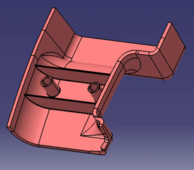
ISOMETRIC VIEW
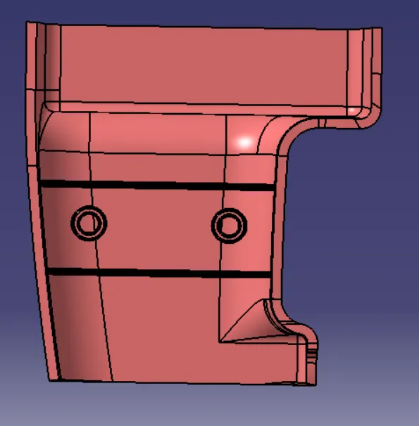
FRONT VIEW
CONCLUSION:
Here we studied RIB and SCREW BOSSES where we use different tools in surface design and part design workbench in CATIA V5 software. In this project first we create solid body of given input class A surface and then create RIB and SCREW BOSSES on solid body, also check their intersection and analyse the draft.
LINK:
https://drive.google.com/file/d/1igHEmHUP4azl6pqJchdoWvSvT-IStabe/view?usp=share_link