Week 10 - Challenge 1- Attachment Feature Creation (Ribs & Screw Boss)
AIM:
- To Build the Door Handle Component from the provided Class-A surface.
- To design a tooling axis that complies with the draught angle requirements for the supplied Class-A Surface.
- To attach the component's B side features.
- to run the model through the Draft analysis.
TOOLS USED:
- Boundary
- Join
- Multiple extract
- Bisecting line
- Trim
- Surface offset
- Draft analysis
- Intersect
- Surface sweep
- Close body surface
- CREATING TOOLING AXIS:
The direction in which an item is pulled out of a mould is known as the tooling direction. Basically, the mould is constructed out of two independent components. You have the Core side and the Cavity side. The Dye line or Tooling Direction is when the Core separates from the Cavity.
CLASS A SURFACE
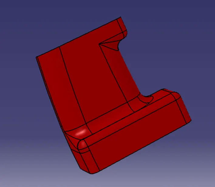
- In relation to the class A surface, intersect the yz plane.
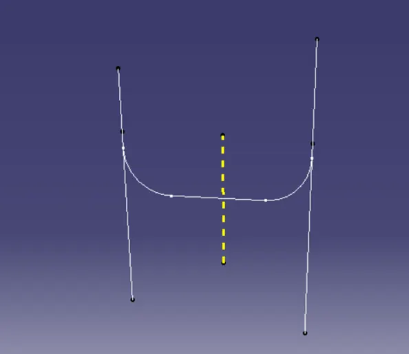
- On the alleged drafts, conceal the class A surface and draw point-to-point lines.
- To construct a tooling axis, draw a bisecting line through the two lines.
- BISECTING LINES were employed to obtain the precise medium from the two sides in order to maximise the positive draught angle.
- The tooling axis is created for the component by bisecting two axes from x and y planes
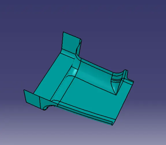
CREATION OF CLASS B SURFACE
CREATION OF CLASS C SURFACE:
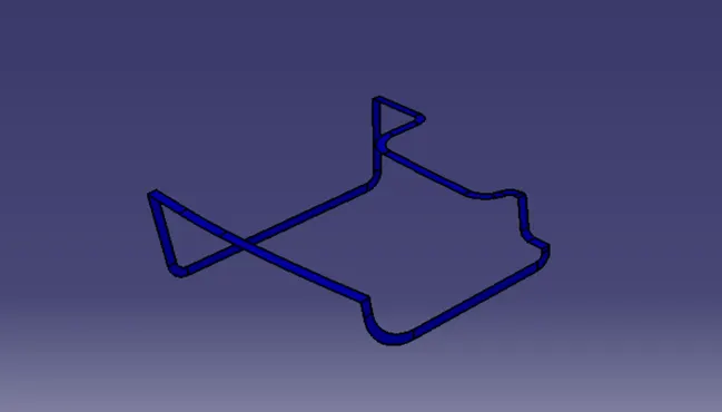
FINAL TRIM:
CLASS A + CLASS B + CLASS C
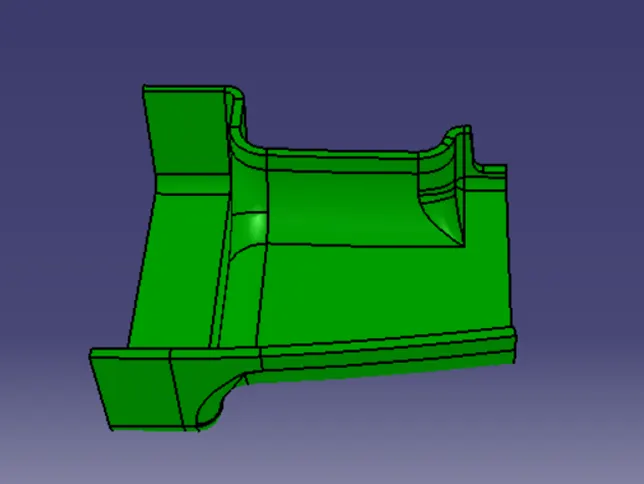
CLOSED SURFACE:
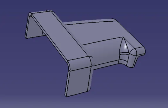
RIB CREATION:
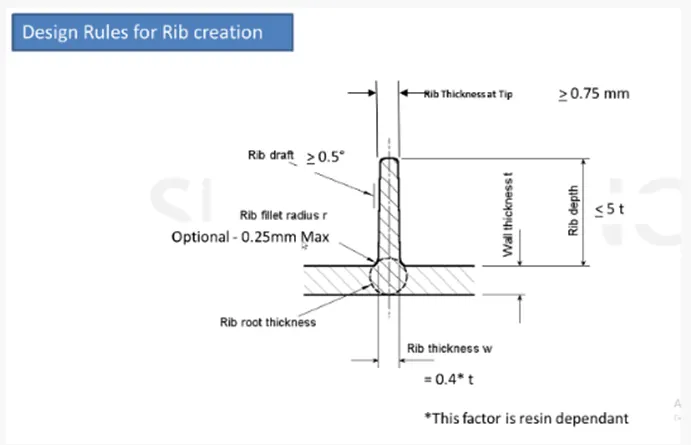
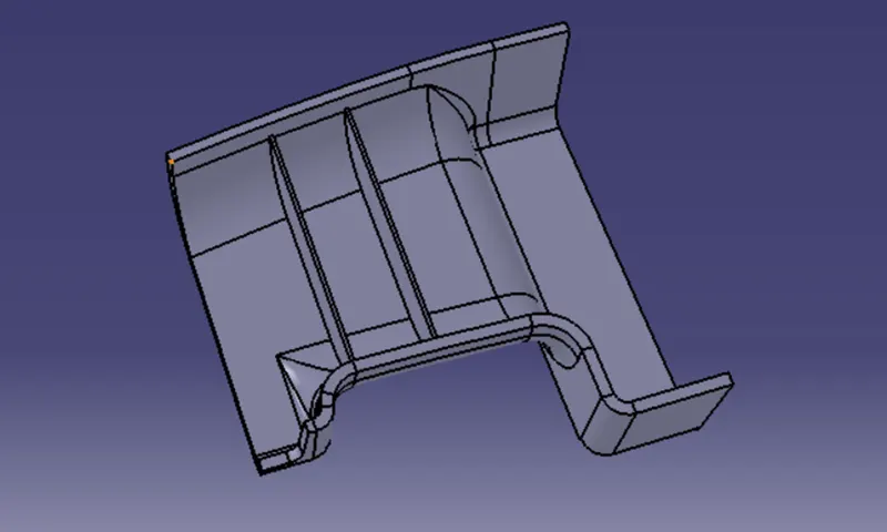
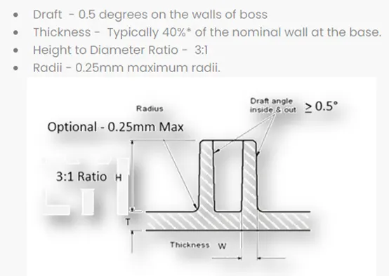
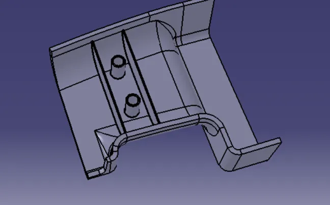
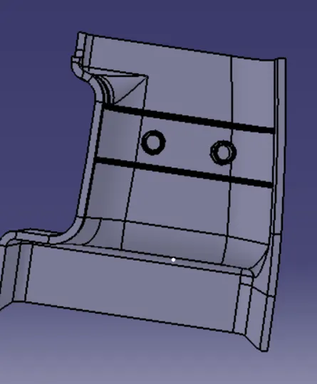
SCREW BOSS DESIGN:
CONCLUSION:
Thus, the rib and screw boss design are successfully done.