Week 10- Assembly Workbench
REPORT:
AIM:TO CREATE ALL THE CAT PARTS SEPARATELY AND ASSEMBLING IT PROPERLY.
PROCEDURE: first we will recieve the sketches of the CAT drawings in a drawing sheet as an input from that we have to make CAT parts out of it.
Here we have to assemble two full components one is CV Joint and another one is quick return mechanism.
so for assembling the parts for example if we are assembling the quick return mechanism we have 5 parts in it so we have to create those parts separately and then we have to assemble it.
so first we will create the quick return mechanism parts one by one.
so our first part sketch will be as follows:
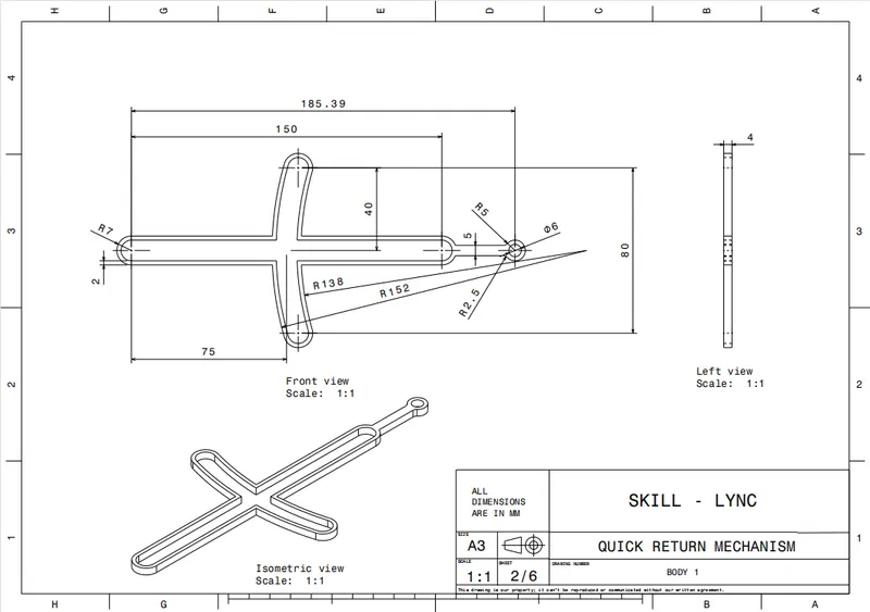
from this sketch we have to make the CAT part of this component.
as usual we will follow the design rules and we will make the CAT part and our output will be as follows:
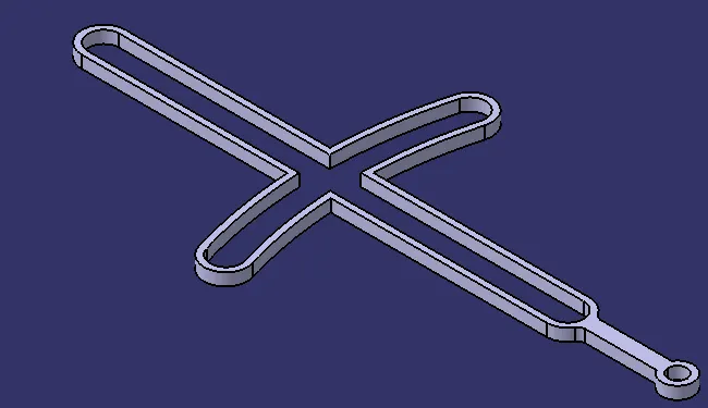
after getting the first part we have to create the second part and our second part sketch will be as follows:
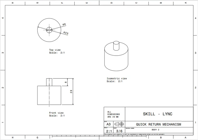
from this sketch we have to make the CAT part of this component.
as usual we will follow the design rules and we will make the CAT part and our output will be as follows:
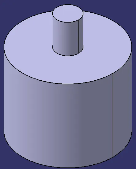
after getting the second part we have to create the third part and our third part sketch will be as follows:
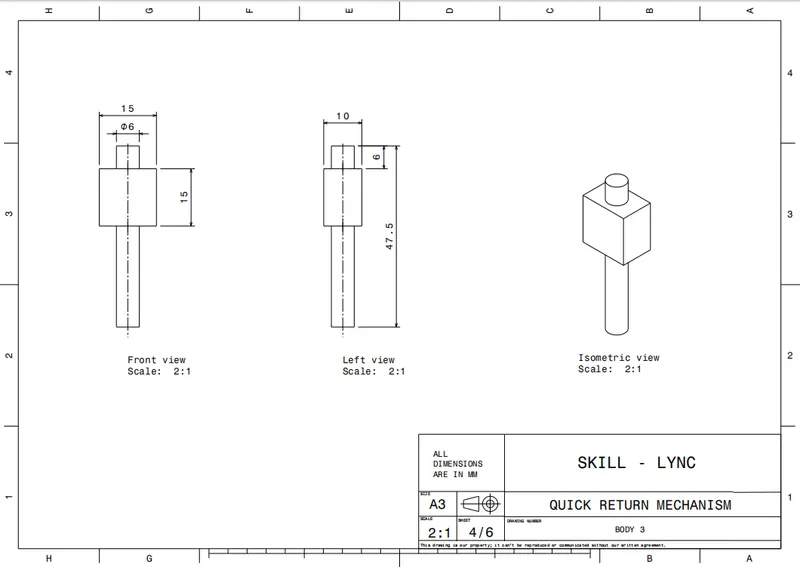
from this sketch we have to make the CAT part of this component.
as usual we will follow the design rules and we will make the CAT part and our output will be as follows:
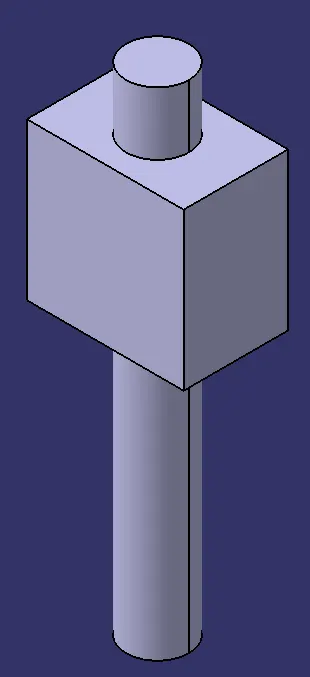
after getting the third part we have to create the fourth part and our fourth part sketch will be as follows:
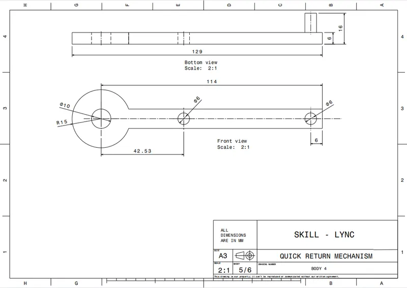
from this sketch we have to make the CAT part of this component.
as usual we will follow the design rules and we will make the CAT part and our output will be as follows:
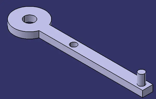
after getting the fourth part we have to create the fifth part and our fifth part sketch will be as follows:
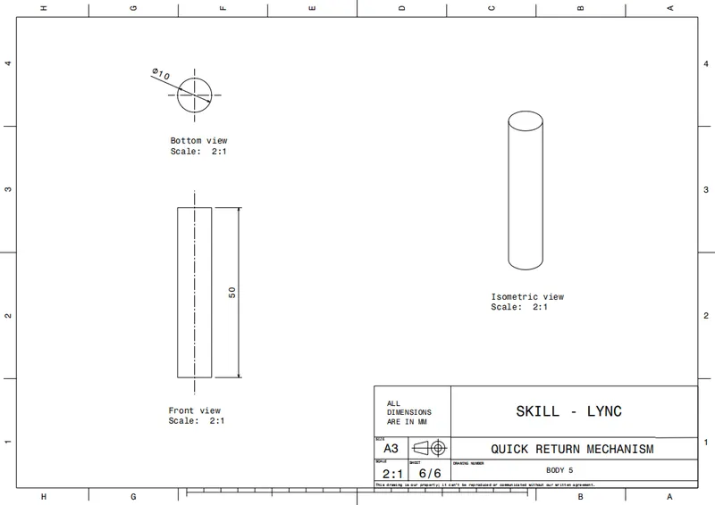
from this sketch we have to make the CAT part of this component.
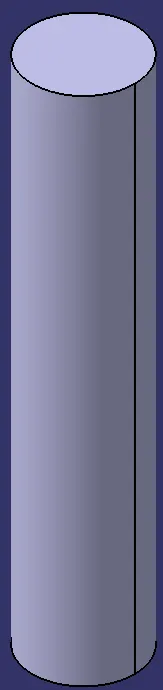
as usual we will follow the design rules and we will make the CAT part and our output will be as follows:
after getting all the parts of quick return mechanism we have to assemble all the parts in the assembly workbench to the refferal image the referral image will be as follows:
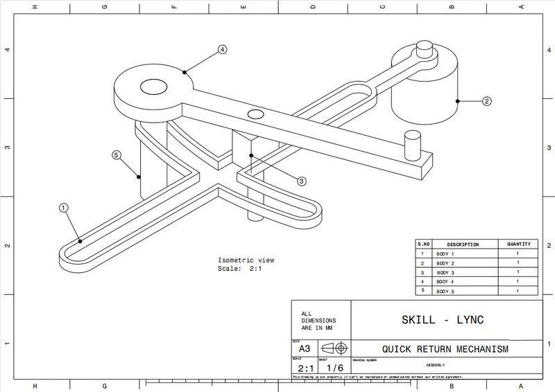
for assembling them all first we will create a reference element geometry set in the each parts in the reference geometry we will create axis in the place where the two parts meet each other for example as the above referral image the number 1 component is meeting the second component so we will create the axis in that place.
after creating the axis in the first component we will create the axis in the second component at the meeting place of the first component after that we will coincide the both axis using coincidence constarint tool and after the we will offset the bottom face of the meeting surface and and the top face of the biggest bush and then our component will as follows:
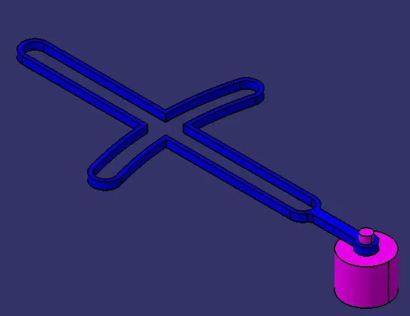
after assembling the first part with the second part we have to assemble the third part to the main part(first part) for assembling the third part we will directly offset one of the face of third part to the required face of the first part to a value of 0mm and then we will offset the bottom face of the third part to the first part of required face to the value of 0mm and then we will recieve the output as follows:
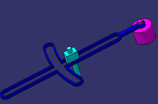
after assembling the third part we will assemble fourth part for assembling the fourth part first we will coincidence the axis of the fourth part to the axis of required axis of the mainpart and then we will offset the required faces for the value of 0mm and then we will get the output as follows:

after assembling the fourth paret we will assemble the final part of the component and then our final component is ready.
for assembling the finnal componentwe will assemble fifth part. for assembling the fifth part first we will coincidence the axis of the fifth part to the axis of required axis of the mainpart and then we will offset the required faces for the value of 0mm and then we will get the output as follows:
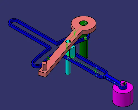
as per the above image our component is fully assembled and it is ready.
ASSEMBLING CV JOINT:
for CV joint we have the sketch in drawing sheets as input and hefre we have three parts:
so our first part sketch will be as follows:
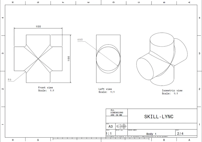
from this sketch we have to make the CAT part of this component.
as usual we will follow the design rules and we will make the CAT part and our output will be as follows:
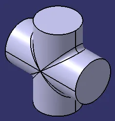
after getting the first part we have to create the second part and our second part sketch will be as follows:

from this sketch we have to make the CAT part of this component.
as usual we will follow the design rules and we will make the CAT part and our output will be as follows:
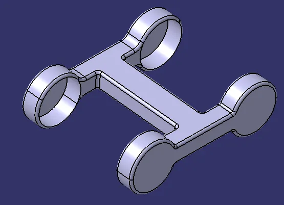
after getting the second part we have to create the third part and our third part sketch will be as follows:
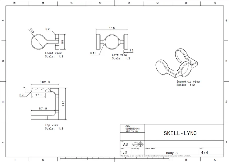
from this sketch we have to make the CAT part of this component.
as usual we will follow the design rules and we will make the CAT part and our output will be as follows:
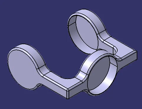
after creating all the CAT parts we have to asemble them for assembling them all together we will use the same rules which we used to do in the quick return mechanism and after doing all that we will recieve the output as follows:
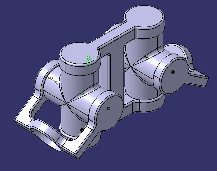
after getting all these we will do the drafting sheets for each parts separately and we will give all as output:
NOTE:PLEASE KINDLY OPEN AND SEE ALL THE FILES IN THE ZIPPED FILE.