Week 10- Assembly Workbench
ASSEMBLY WORKBENCH
AIM: In the assembly workbench we create a CAT product by assembling the CAT parts of the components which are created seperately in the part work bench by providing required constraints for the assembly.
OBJECTIVE: In the part workbench first we need to create the parts of an assembly with suitable dimensions provided and then the assemly 0f the components are done in the assembly workbench by providing the suitable constraints in order to restrict the motion of the components with relevant to the other components
PROCESS:
- Creation of CAT parts of the individual components
- Generating the assembly for the components
- Creating the reference elements
- Publishing the reference elements
- Providng the constraints
- Saving the component
- Developing the CAT drawings of the components
ASSEMBLY 01:
QUICK RETURN MECHANISM
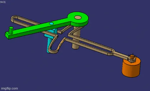
The Quick return mechanism is the inversion of a single slider crank chain.The main purpose of this mechanism is to convert the rotary motion of the crank into the reciprocating motion of the ram.In this mechanism, the movement of reverse stroke is faster than the forward stroke. The mechanism is generally used in applications where the velocity of the tool at return stroke is not considerable.
The Quick return mechanism consist of the following key components:-
1] Crank: The crank is connected to the pinion wheel or motor and rotates with a uniform angular velocity.
2] Slider & Slotted bar: The slider is pivoted at the end of the crank. This slider moves freely into the slotter bar. This component is used to convert the circular motion of the crank into the oscillating motion of the slotted bar.
3] Connecting rod: The purpose of the connecting rod is to convert the oscillating motion of the slotted bar into the reciprocating motion.
4] Ram: The ram reciprocates in the horizontal direction along the line of stroke.
Some of the applications of the Quick return mechanism are as follows:-
- Shaper machine
- Slotting machine
- Mechanical actuators
- Rotary internal combustion engine
- Mechanical cutter
- Air compressors
- Power saws
In the following assembly we assemble the simple quick return mechanism using the components
- Dead load
- slider
- .slottted bar
- Slider
- Transltory pin
Design of the following part components:
Creation of CAT parts of the individual components :
Dead load:
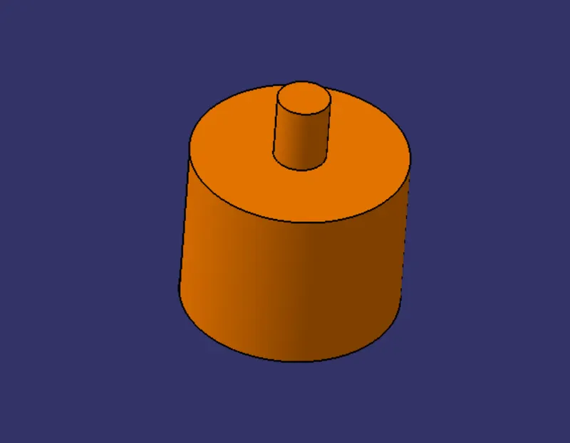
Crank:
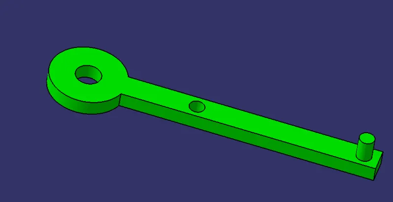
Slotted bar
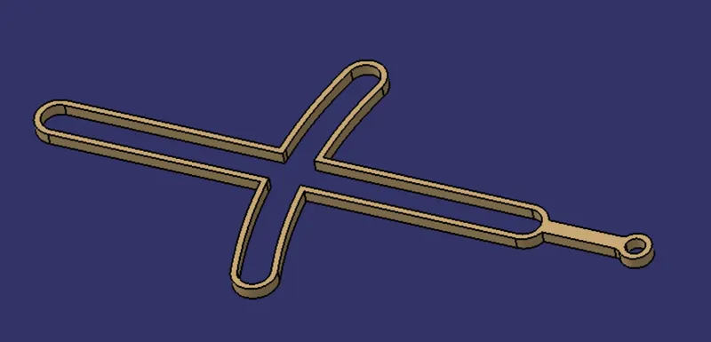
Slider
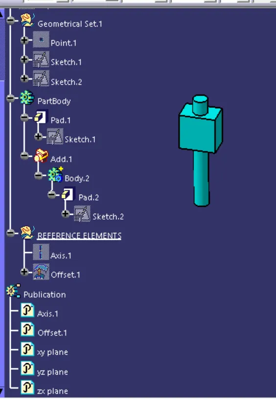
TRanslatory pin:
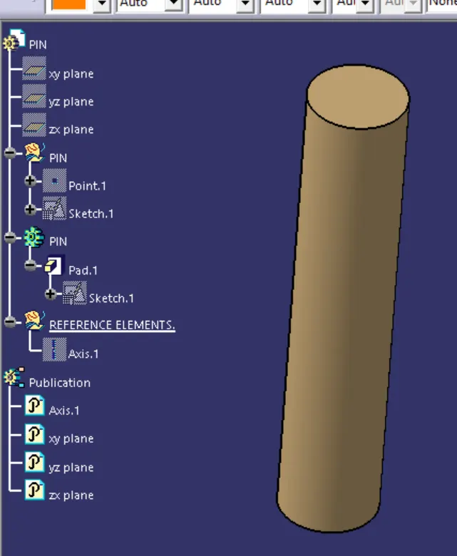
when once all the CAD part compone ts are created with the help of the CAD drawings priovided then we need to go on to the assembly workbench to generate the assembly of the component
Generating the assembly for the components:
Go to Start< mechanical design< assembly design then the home screen would be like and the componenmt can be saved in the form of CAD. product
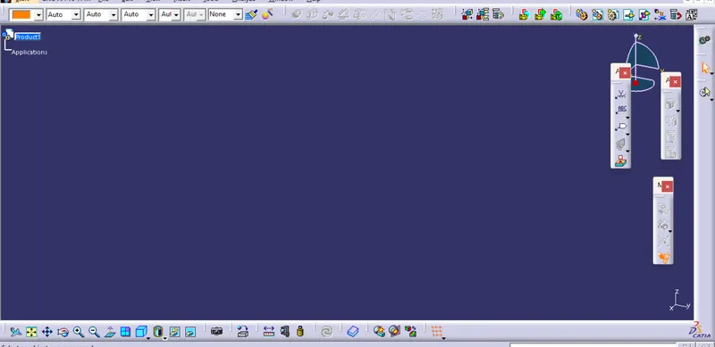
Then we can lay on the commands or the features include the.
Now there are the two ways to input the part components in the assembly workbench .
1 . Copy the individual part component and paste it in the assembly workbench space
2. Select the cAD product and use the existing component command to input the part componemts one by one in the workbench
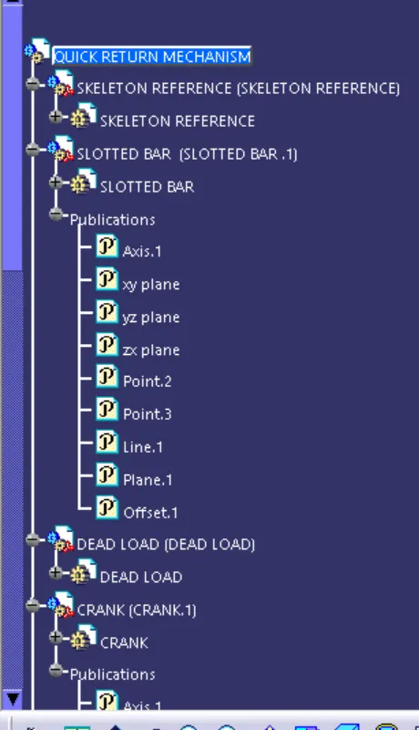
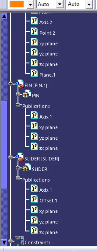
Once all the part componets are inserted in the workbench then start to create the reference elements for the componets and publish them
Reference elements for the slotted bar:
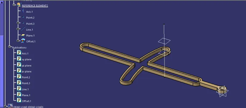
Reference elements for the crack:
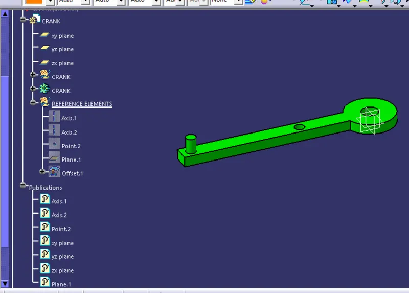
Reference elements for the slider:
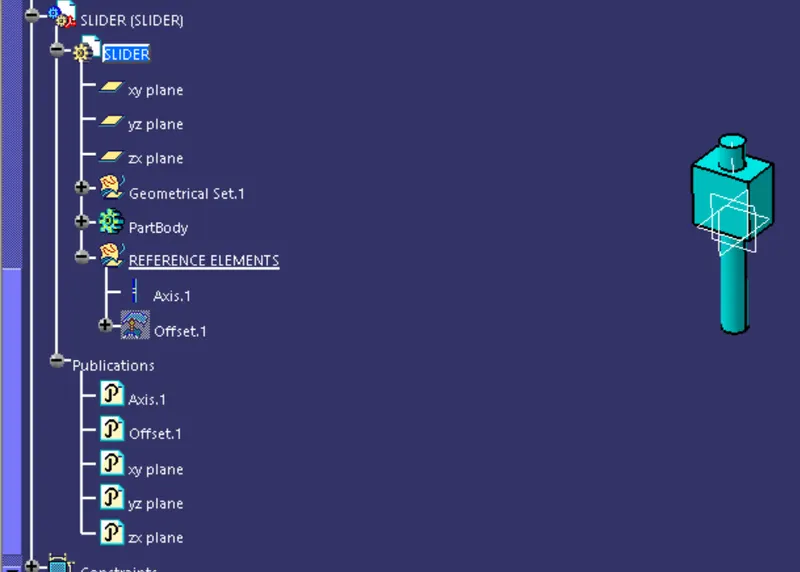
Reference elements for the dead load:
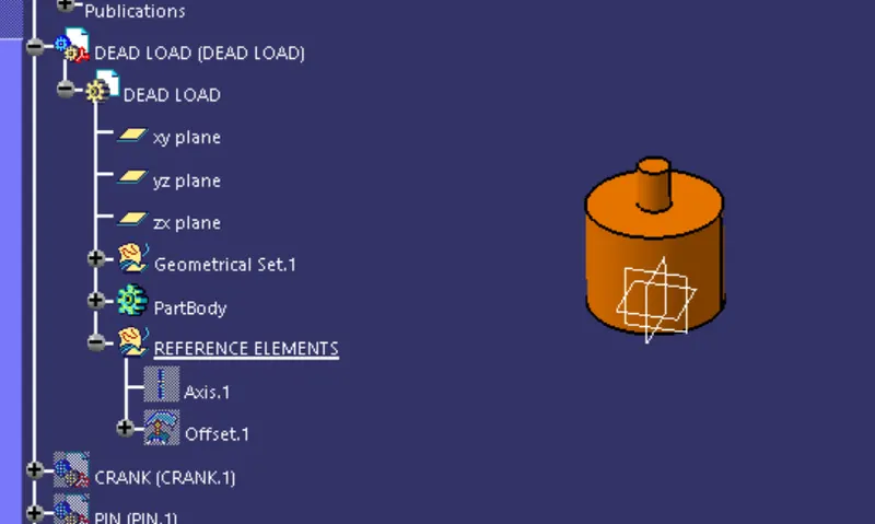
Reference elements for the pin:
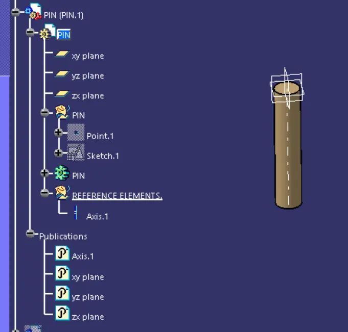
Now create the new part componet with the zero reference point and name it as the Skeleton reference
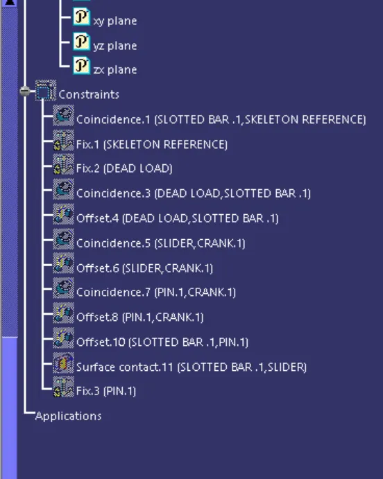
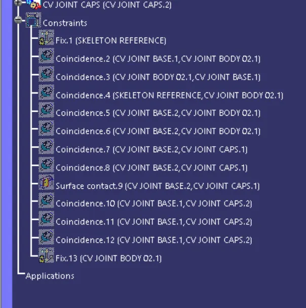
Then apply the proper constraints to stabilize the each one of the component with the other one and restrict their degrees of freedom
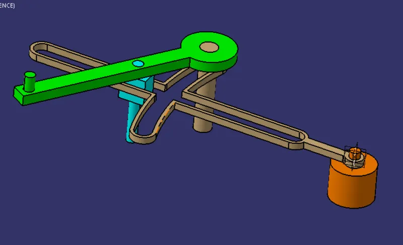
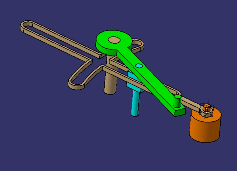
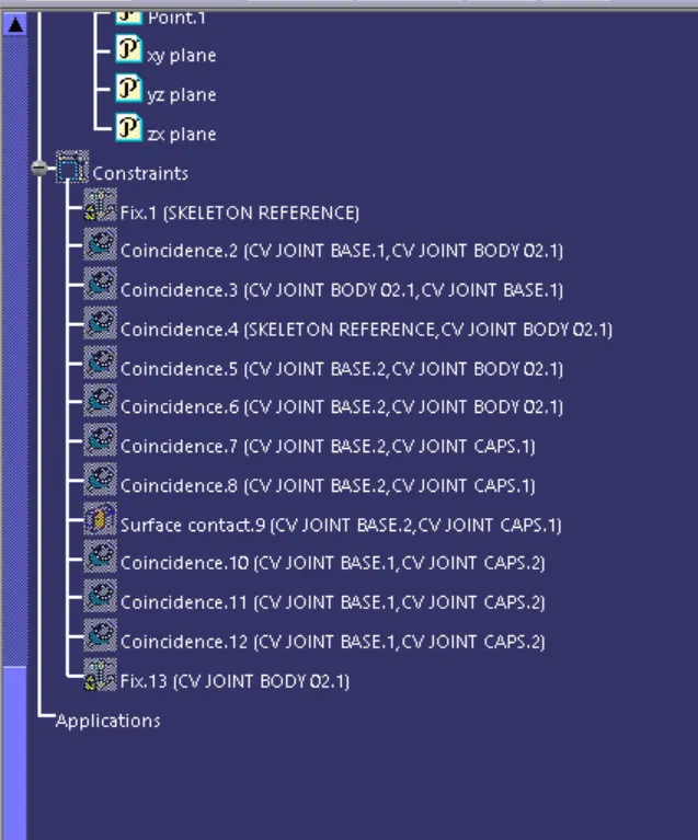
The constraints applied are
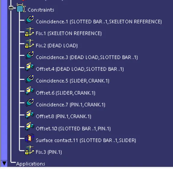
By fixing the respective necessary component check the motion of the assembly as it is upto the conditions or else redefine the constraints properly asthe components are making the motion with respect to the other elements of the componemts
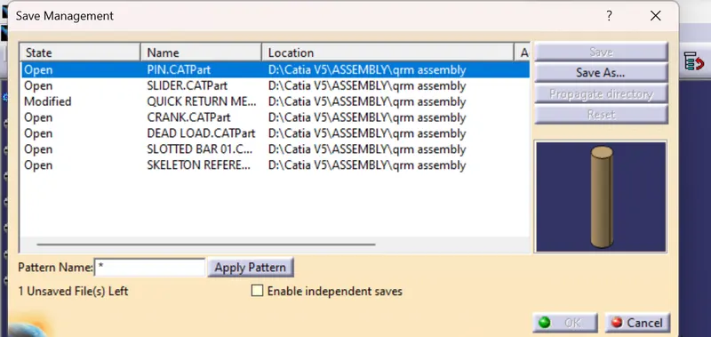
SAVING THE ASSEMBLY :
Go to the file < save management < then save as the Cad product < then click on the prropogate directory to save the part components along with the assembly product .
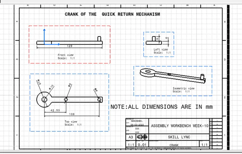
Now generate the CAD drawimg for the part components with drafting workbench the followings are the CAD drawings
CRANKCAD DRAWING:
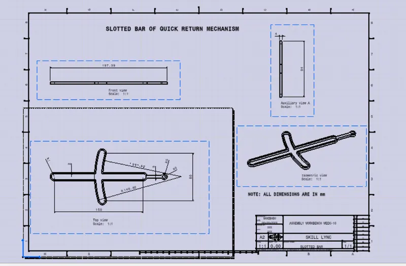
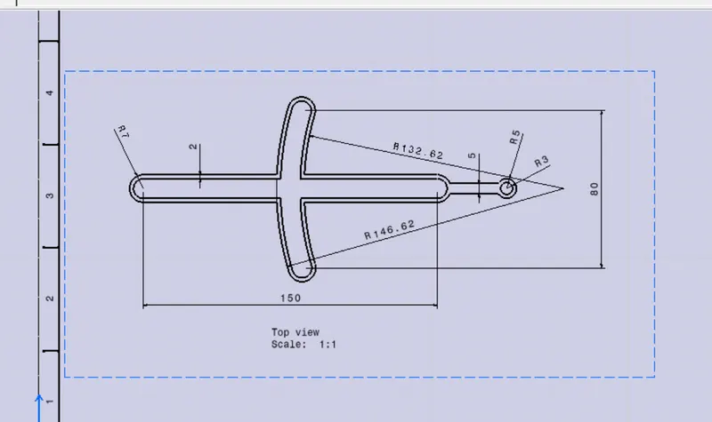
SLOTTED BAR CAD DRAWING:
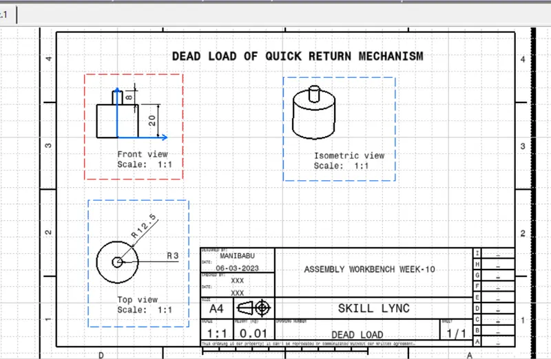
DEAD LOAD CAD DRAWING:
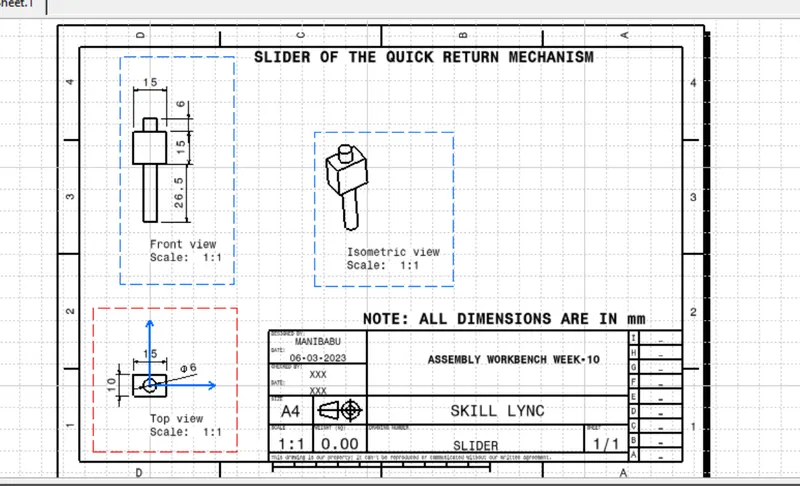
SLIDER CAD DRAWING:
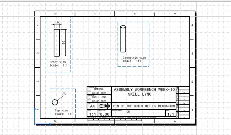
PIN CAD DRAWING:
ASSEMBLY 02
CONSTANT VELOCITY JOINT:
A constant-velocity joint (also called a CV joint) is a mechanical coupling which allows the shafts to rotate freely (without an appreciable increase in friction or backlash) as the angle between the two shafts moves within a certain range.A common use of CV joints is in front- wheel drive vehicles, where they are used to transfer the engine's power to the wheels, even as the angle of the drive shaft varies due to the operation of thesuspension
Now create the part components for the assembly
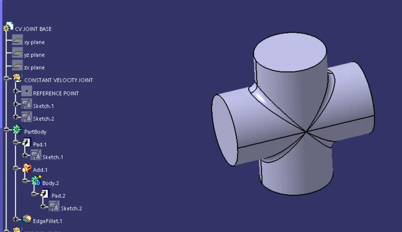
Body 01
Body 02
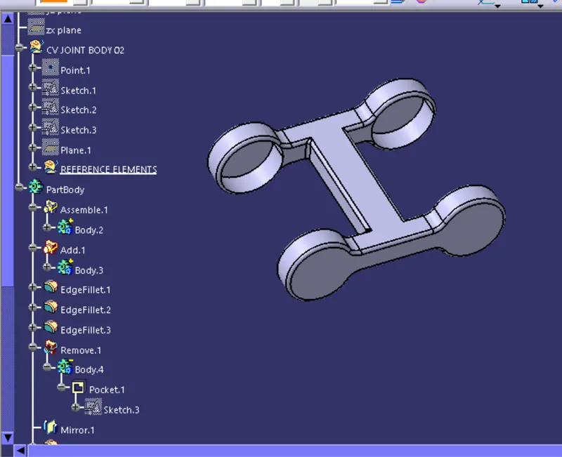
Body 03
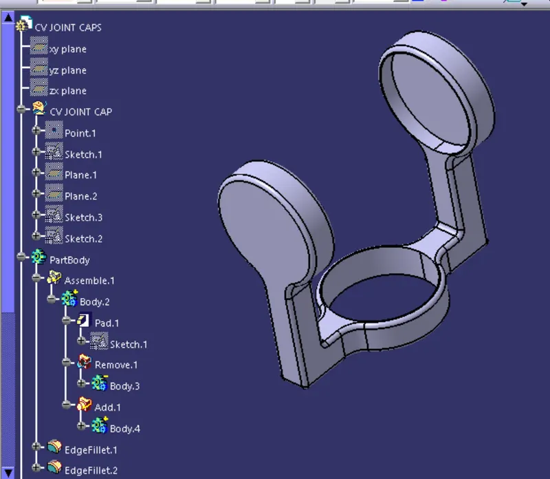
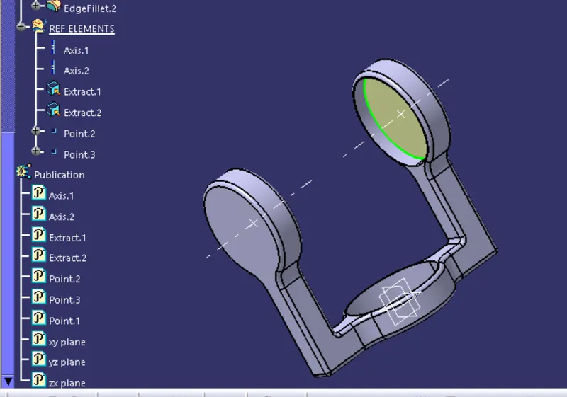
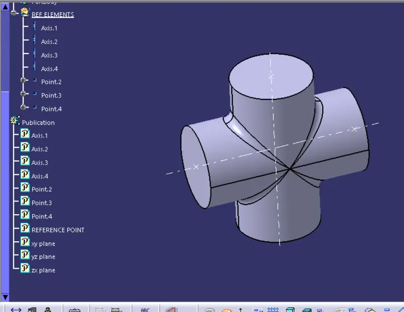
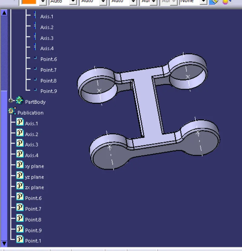
CREATE THE REFERENCE ELEMENTS FOR THE PART COMPONENTS AND PUBLISH THEM WHICH WILL PROVIDE THE AID FOR THE ASSEMBLY PRODUCT
Reference elements for body 01:
Reference elements for the body 02:
Reference elements for the body 03
Now create the new part componet with the zero reference point and name it as the Skeleton reference
Then apply the proper constraints to stabilize the each one of the component with the other one and restrict their degrees of freedom
Now the final assembly will be
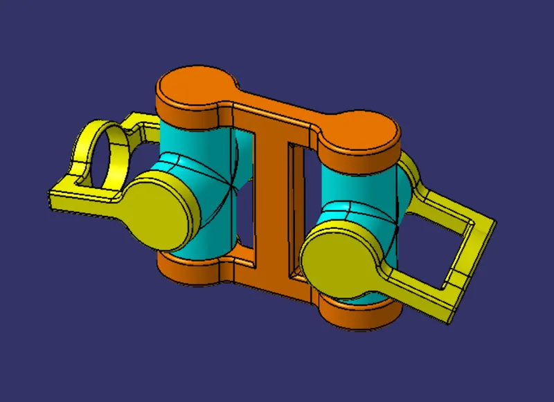
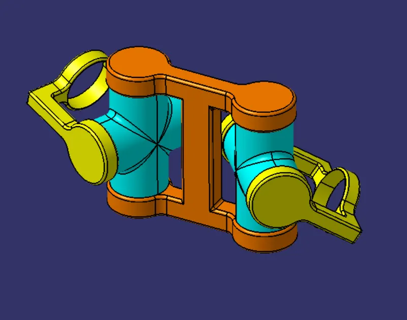
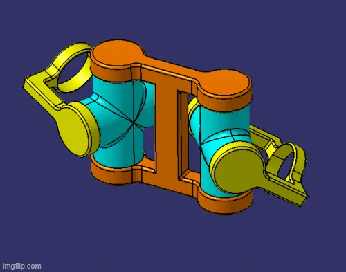
The motion will be
Now generate the CAD drawimg for the part components with drafting workbench the followings are the CAD drawings
CAD DRAWING FOR THE PART BODY 01
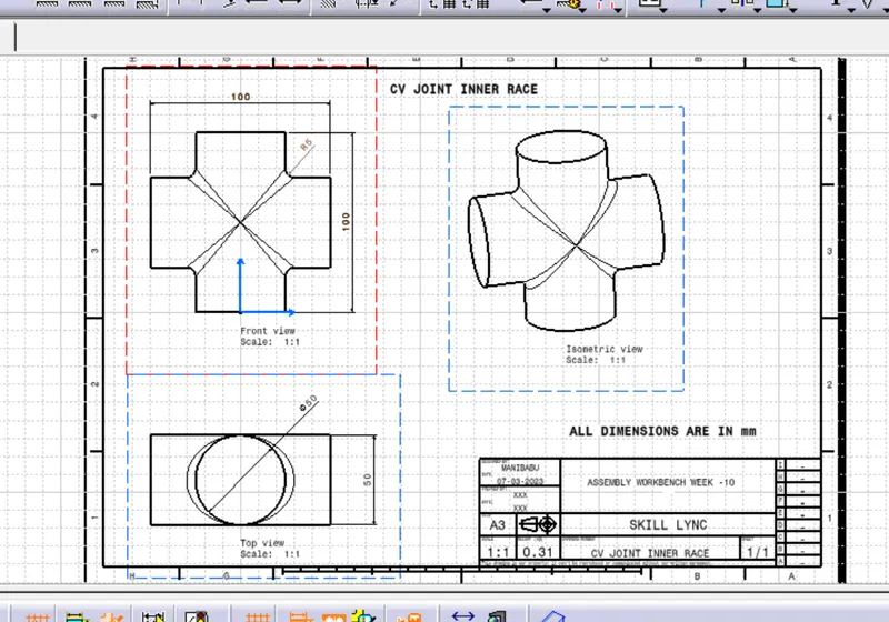
CAD PART DRAWING FOR THE BODY 02
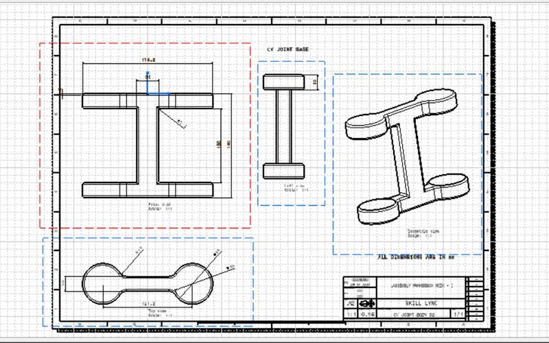
CAD PART DRAWING FOR THE BODY 03
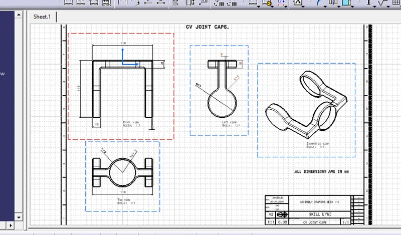
CONCLUSION:
So, the part componemts of teh assembly are cerated individually and the assembly product is genertaed with the part components by craeting the reference elements for positioning the components with each other and there by providing the proper constraints to restrict the unwanted degree of their motion and the zip file is sumitted along with the report
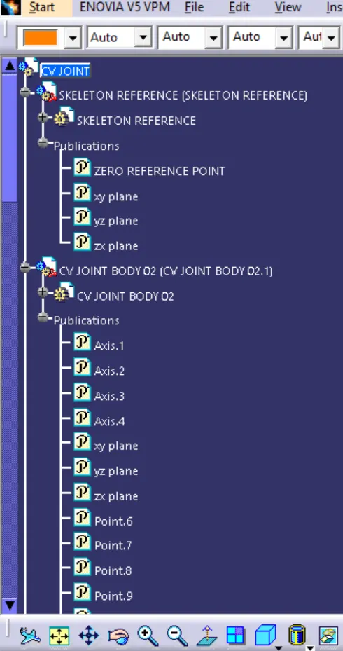
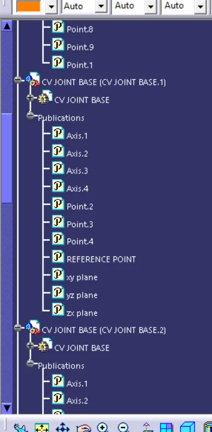
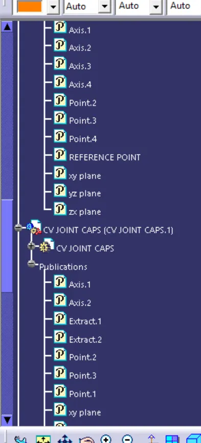
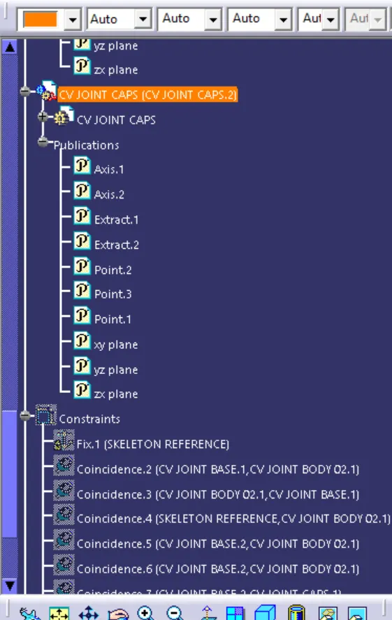
TREE STRUCTURE
CV JOINT.
QUICK TRETURN MECHANISM