Week 10- Assembly Workbench
'ASSEMBLY WORKBENCH'
Introduction :
In real life assembly of products means mating of two or more parts together to perform a function such as assembly of rim wheel , tyres and Disc plate and callipers etc in a vehicle. In modern approach before assembling the parts in reality the parts are created in CAD( computer aided design ) softwares and are assembled in assembly workbench.
Assembly in any cad software can be followed by two approaches such as:
A) Bottom up Assembly : In this type of approach the parts are created individually in part workbench and then are assembled in assembly workbench with the help of geometrical constraints and other features. In this assembly project i followed bottom up assembly approach.
B) Top down Assembly : In this type of approach the parts are created inside the assembly workbench by starting the product file and then creation of individual parts is carried out and they can be opened separately in part workbench.
However we can also use both types of assembly combination at a same time if some parts are created while others can be created in assembly workbench.
Important parameters in CATIA design software :
A) The part file extension is (*.CATPart ) file which was created by Dassault systems. CATPart (or “CATPART”) is used to store part models and includes 3D geometrical and structural data.
B) The assembly file extension is a (*.CATProduct) file which is a type of assembly file created by the dassault system software application and is used to store product models

This is how it displays a product file and a part file
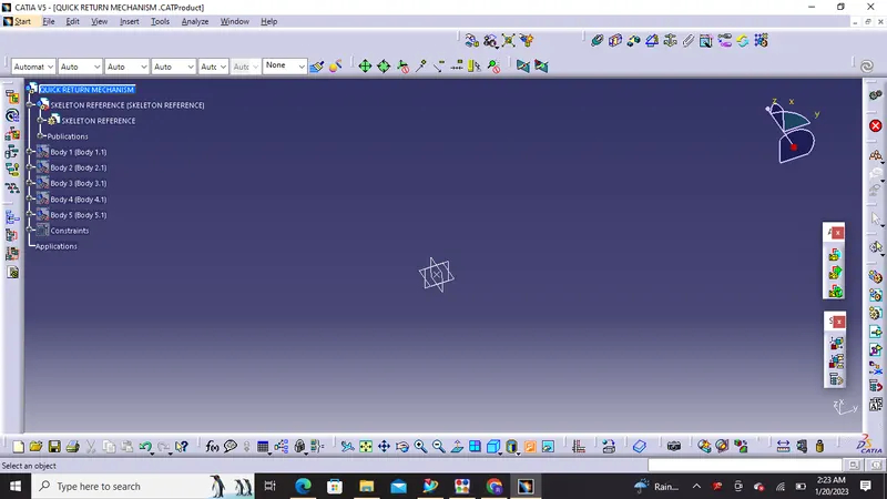
Assembly workbench in Catia has a product in top and all other parts come under it :
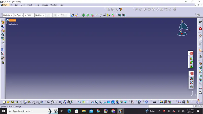
A visual look of Assembly workbench
Part workbench has part on top under which geometrical sets and part body are created
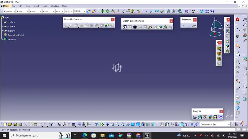
A visual look of Part workbench
Steps followed in Assembly workbench :
1) A skeleton reference is made as a part in which planes and reference point is created and fix constraint is added at that reference point.
2) we can click on existing component to insert our part files
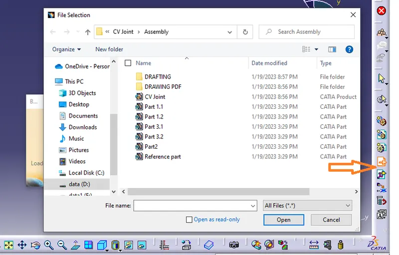
The orange arrow on the right side is used for inserting existing components
3) Once the parts are inserted then we need to create reference axis and reference points on individual parts and then publish it
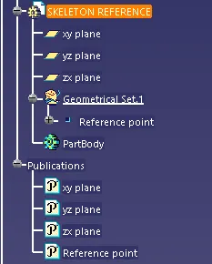
A publication acts as a reference to a geometric or datum entity in CATIA V5.
Advantages of using Publications in CATIA V5.
Publishing geometry has the following advantages:
- Published geometry can be given a name which can easily be recognized e.g. in case of publishing edges, faces ,axis etc.
- Publications are used to make a particular geometry easily accessible from the specification tree.
- By using the required setting, only published elements can be used as an external reference if it is the requirement.
- Publications are very helpful when replacing one component of an assembly with another because published elements having the same name are automatically reconnected during replacement. Else one would have to reconnect them manually if they were not published.
4) Now we have all the parts with reference axis and points now we need to assemble the main base part in the main skeleton reference and then fix all other parts by giving constraints and manipulating their locations according to the requirement
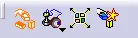

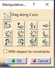
The above images shows different manipulation tools and constraint toolbars with (coincidence,contact,offset,angle ,fix etc ) functions .
INPUT GIVEN:
1) Quick Return Mechanism :
A quick return mechanism converts rotatory motion into reciprocating motion,It is driven by a circular motion source and uses a system of links with three turning pairs and a sliding pair
2) CV Joint :
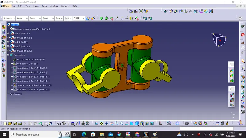
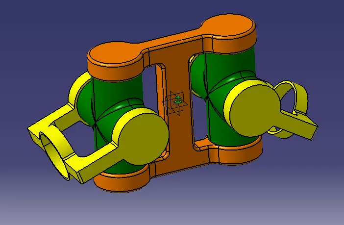
Constant-velocity joints (also known as homokinetic or CV joints) are mechanical joints which allow a drive shaft to transmit power through a variable angle, at constant rotational speed, without an appreciable increase in friction or play They are mainly used in front wheel drive vehicles. Modern rear wheel drive cars with independent rear suspension typically use CV joints at the ends of the rear axle halfshafts and increasingly use them on the drive shaft.
Design & Assembly of Quick Return Mechanism
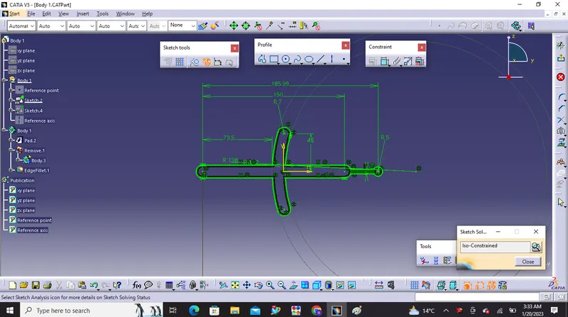
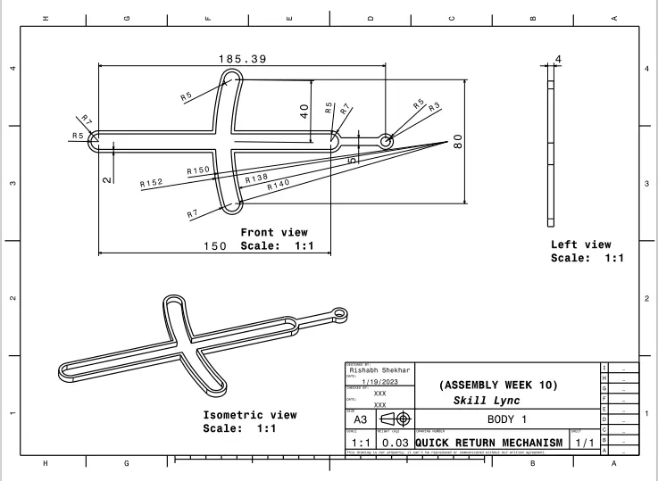
1) Body 1
Sketches :
Drafting:
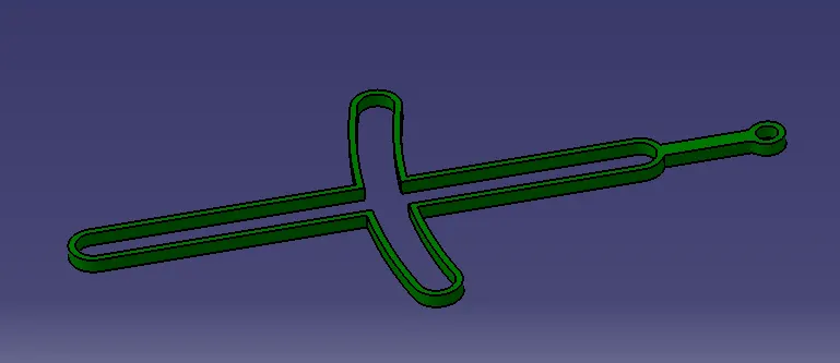
2) Body 2
Sketches :
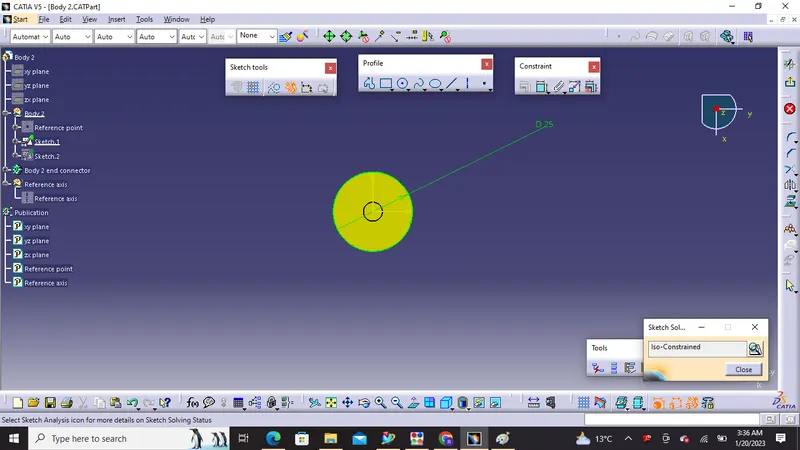
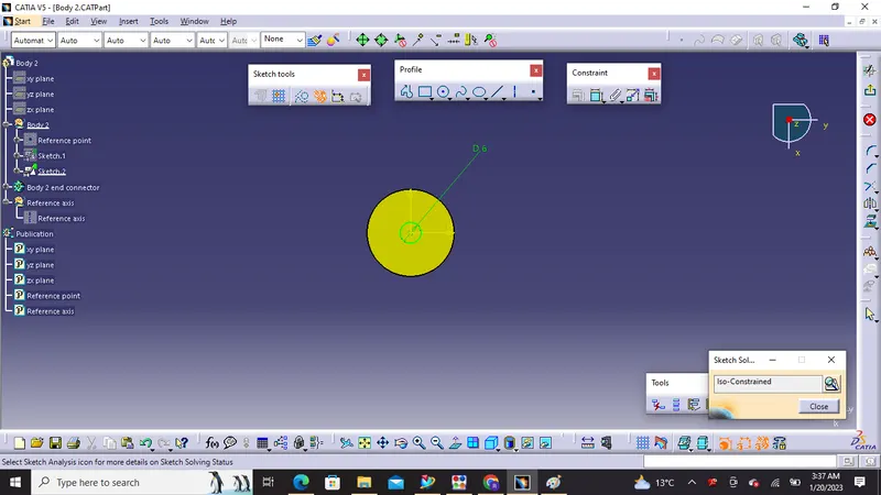
Drafting :
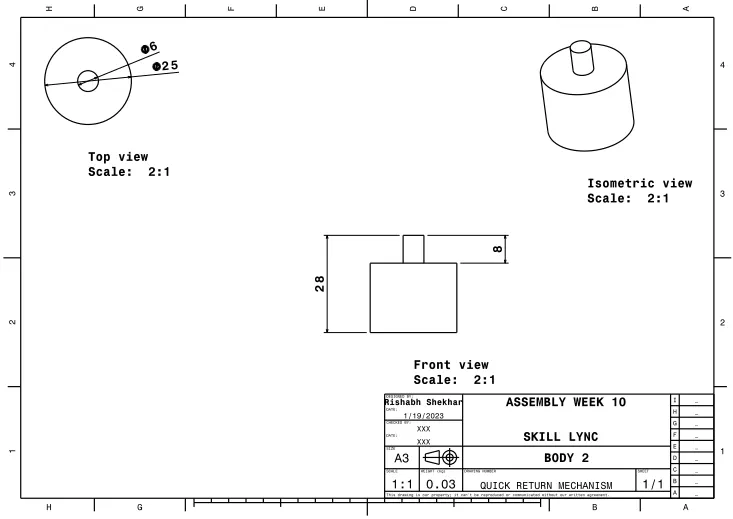
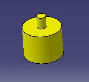
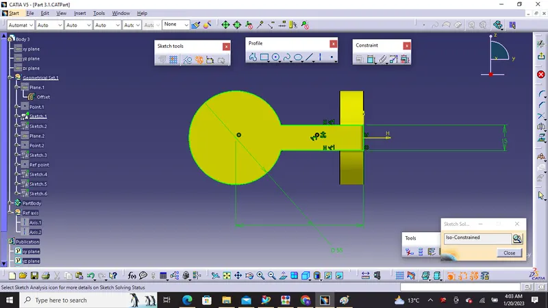
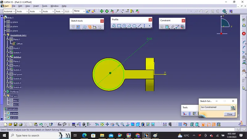
3) Body 3
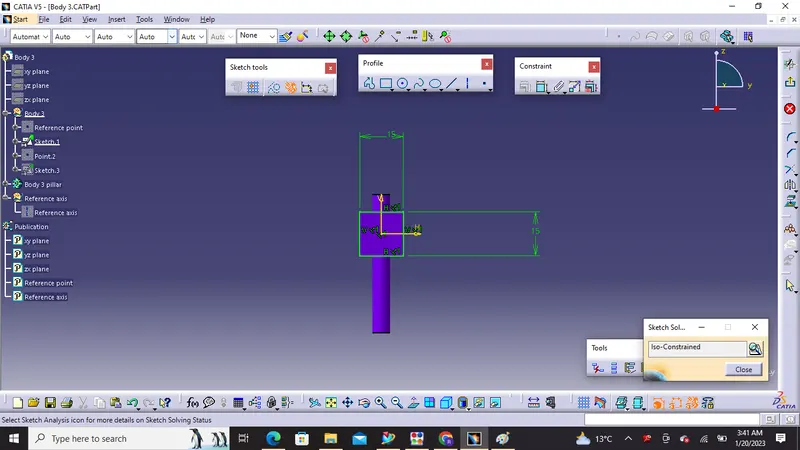
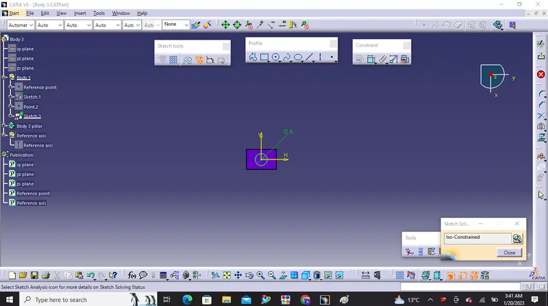
Sketches :
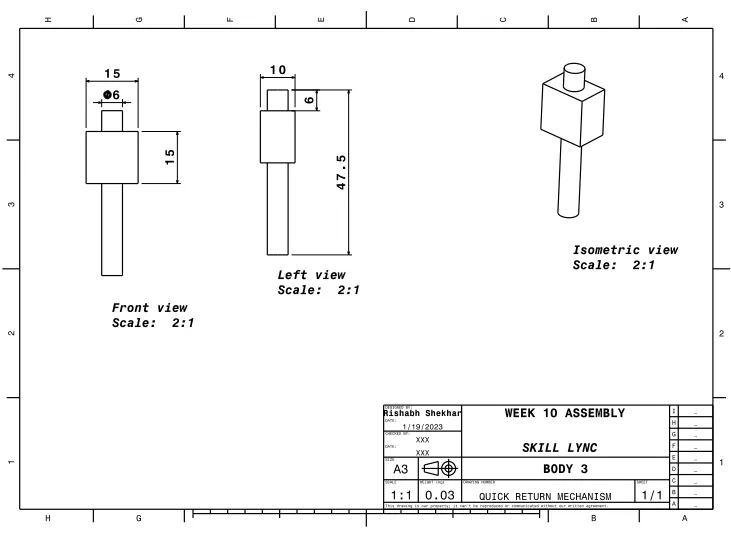
Drafting :
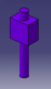
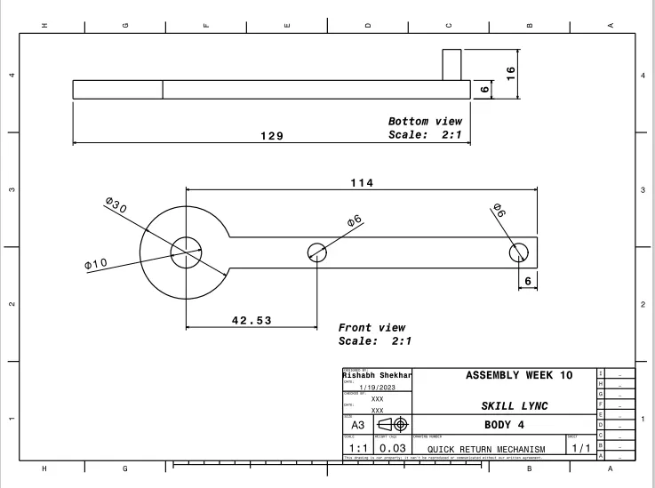
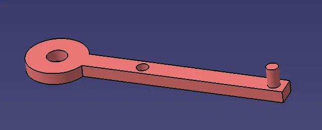
4) Body 4
Sketches :
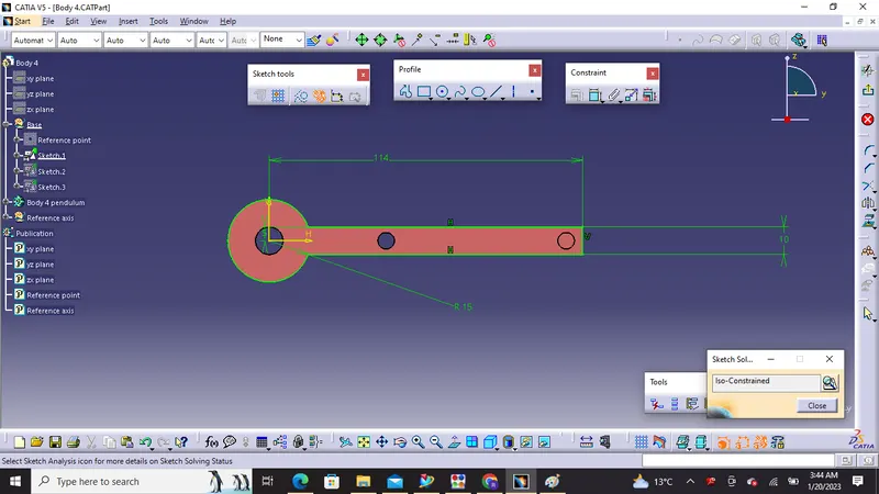
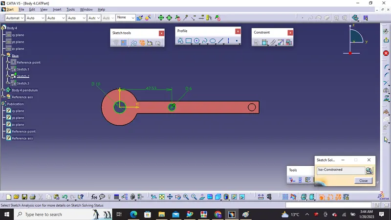
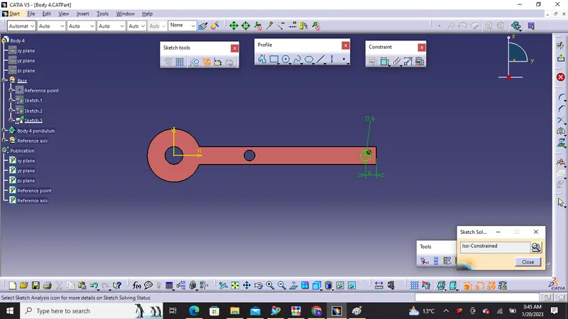
Drafting :
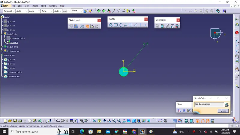
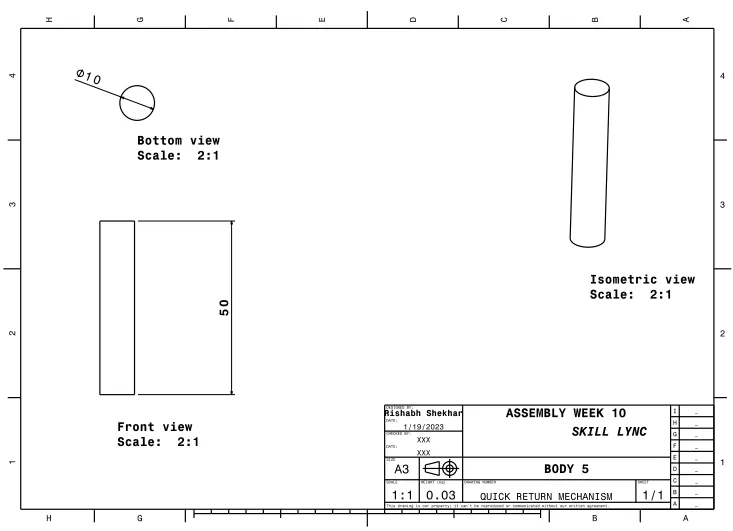
5) Body 5
Sketches :
Drafting :
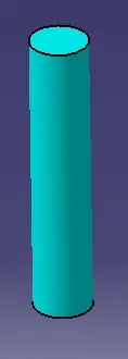
Final Assembly:
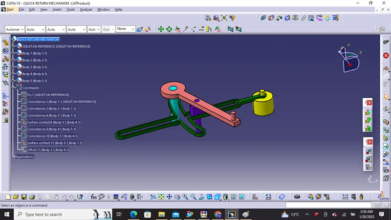
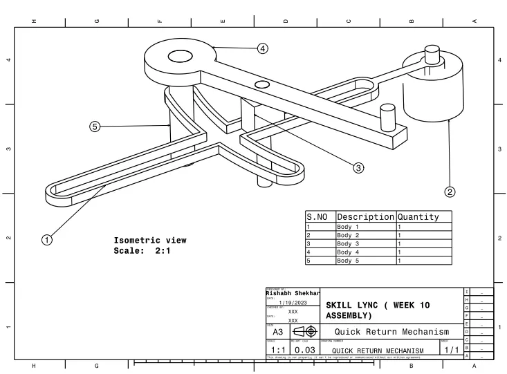
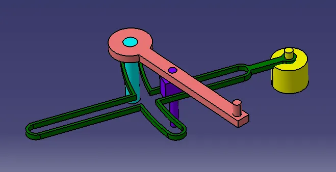
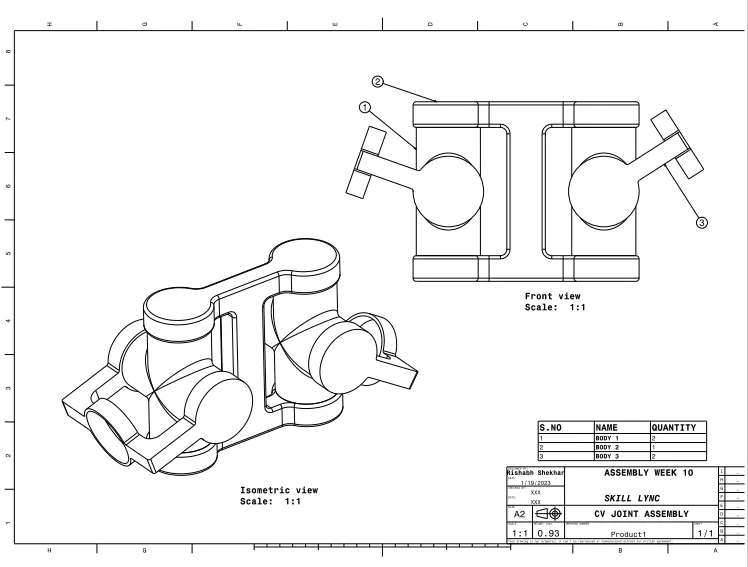
Design & Assembly of CV JOINT
1) Body 1
Sketches :
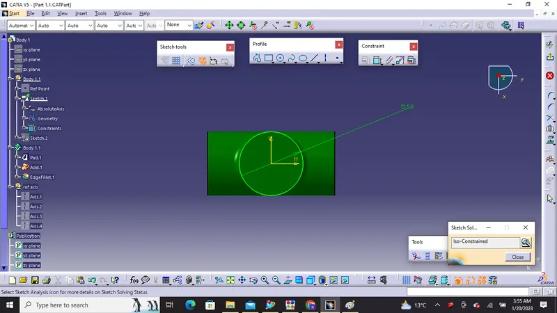
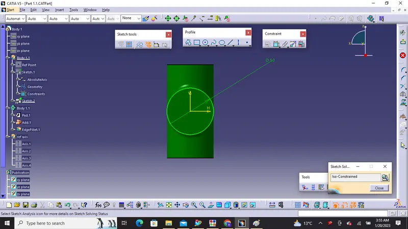
Drafting :
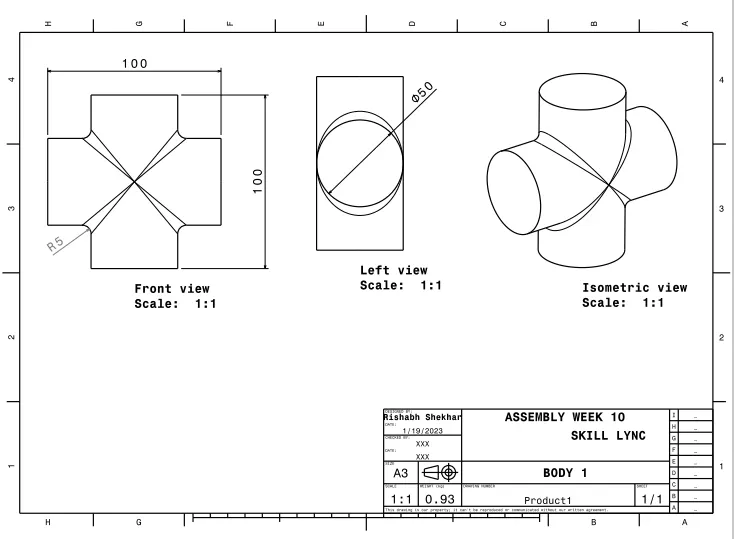
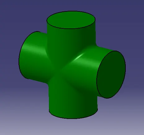
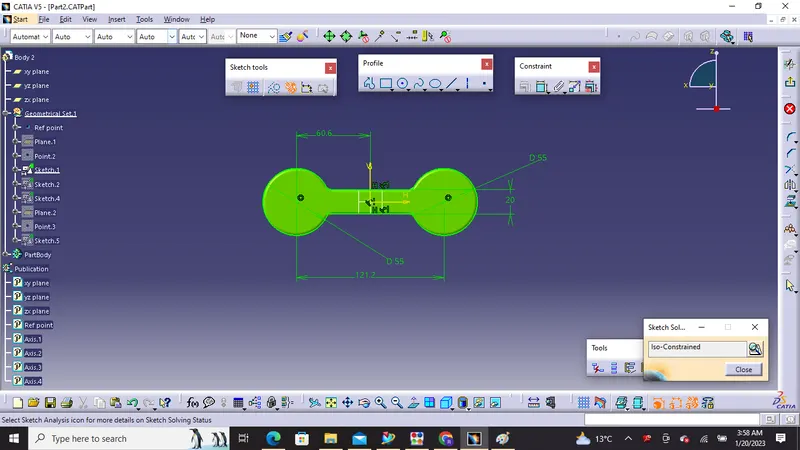
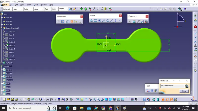
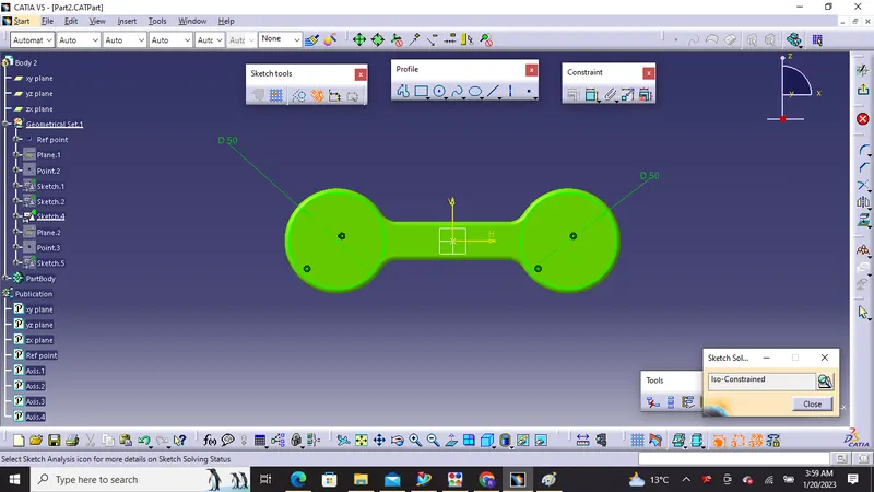
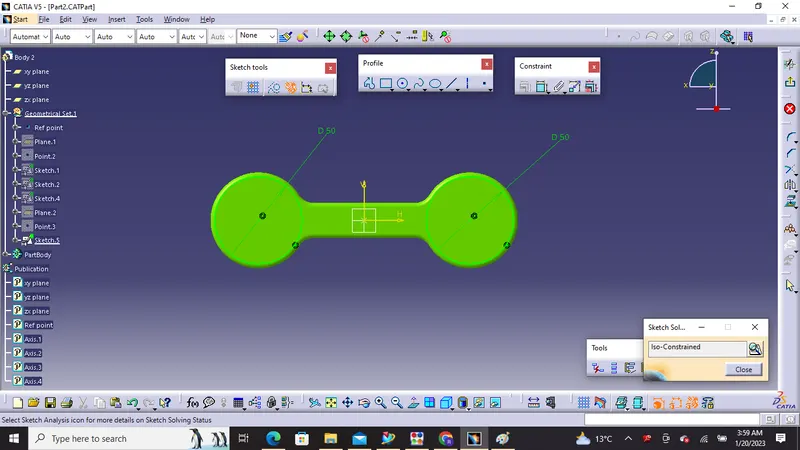
2) Body 2
Sketches :
Drafting :
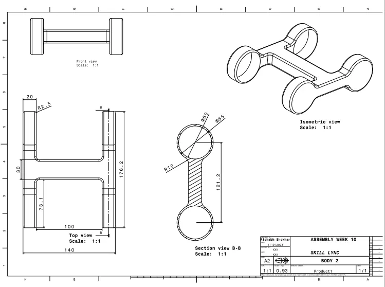
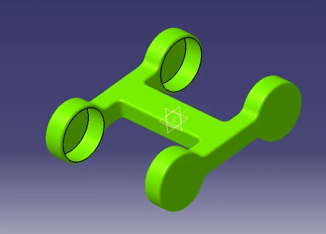
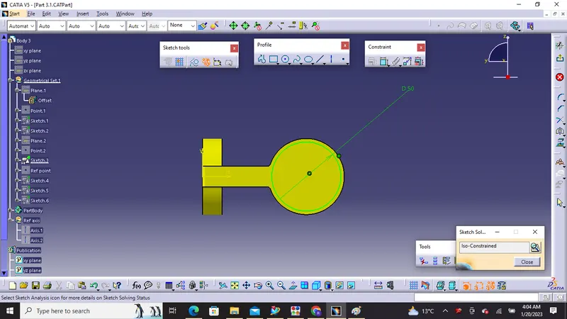
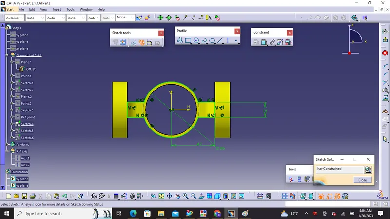
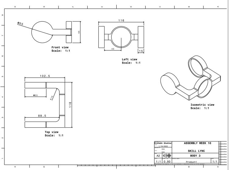
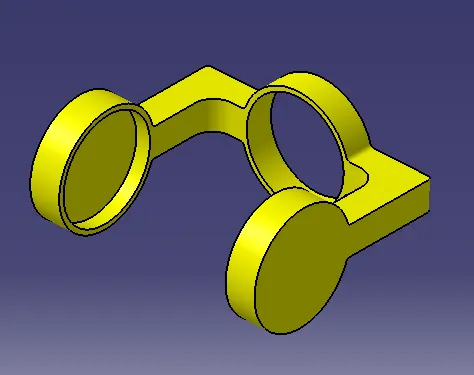
3) Body 3
Sketches :
Drafting :
Final Assembly :