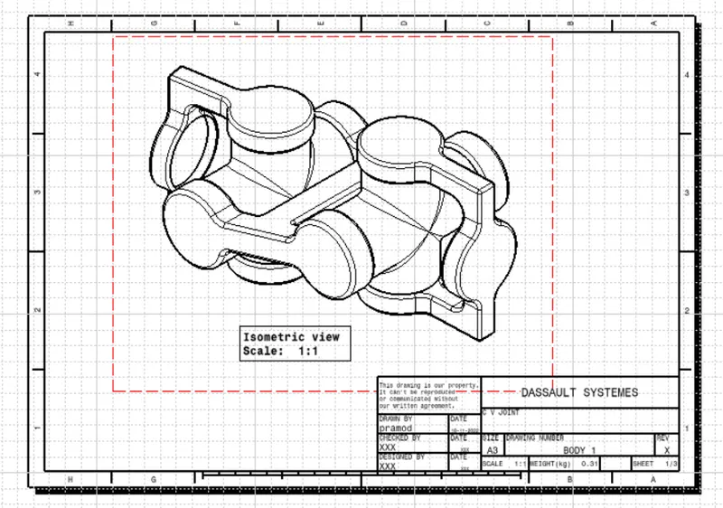
Week 10- Assembly Workbench
We have received 2-D diagram , so our first task will be making solid of 2-D diagram.
For Quick return motion mechanism
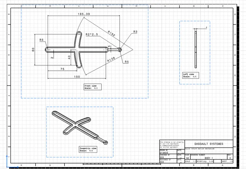
Body -1
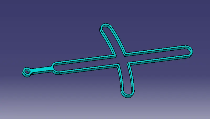
- Make a sketch as shown in below image.
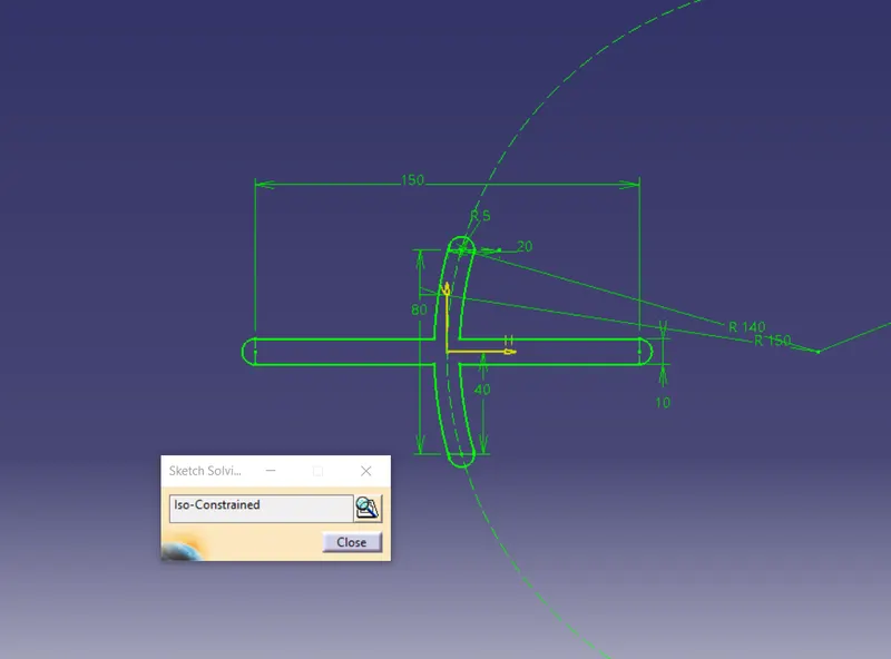
- Use the multi pad , click on thick and provide the thickness 2mm outter way and length= 4mm
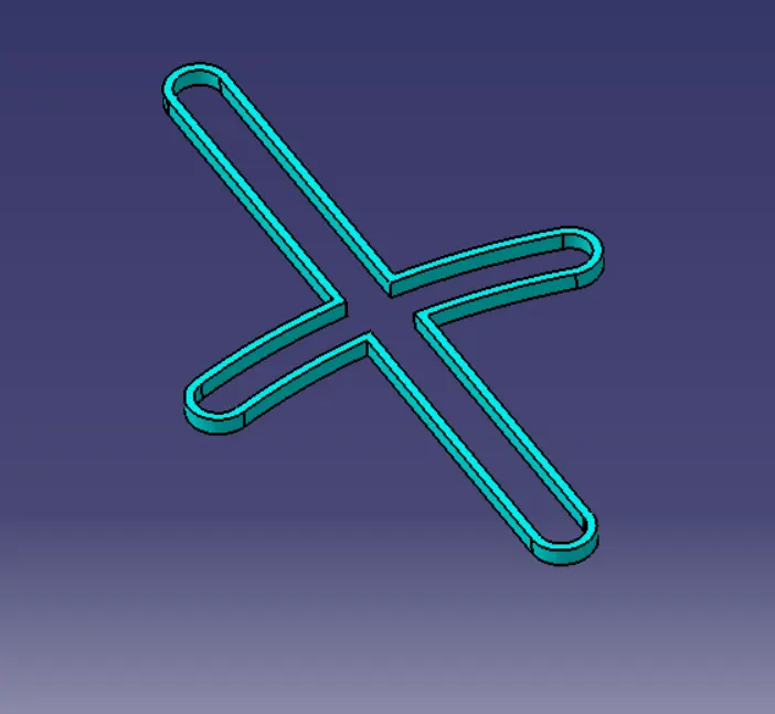
- Make another sketch as shown in below image
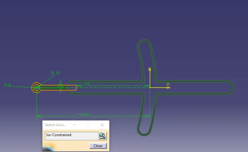
- Pad it and use unoin trim and body 1 is ready.
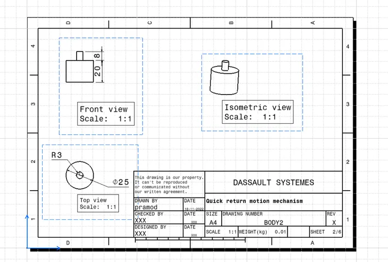
FOR BODY- 2
- Make a sketch as shown in below image.
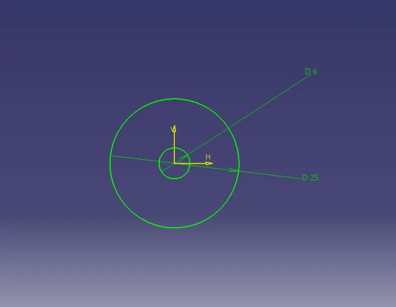
- Now use multi pad and body 2 is ready.
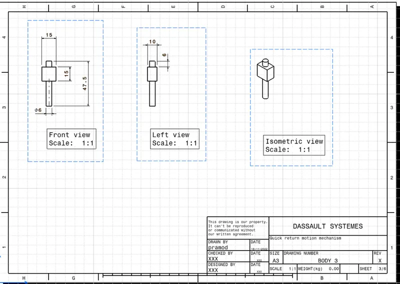
FOR BODY 3
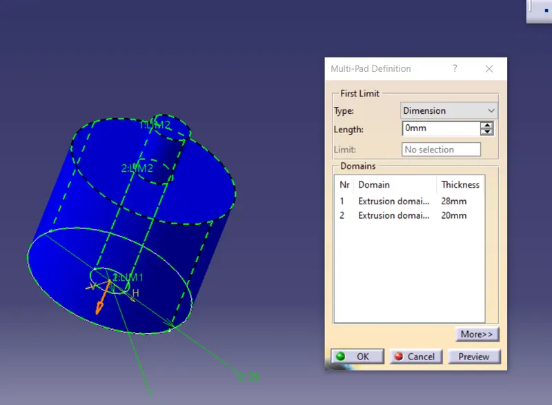
- Make a sketch as shown in below image and pad 10 mm length.
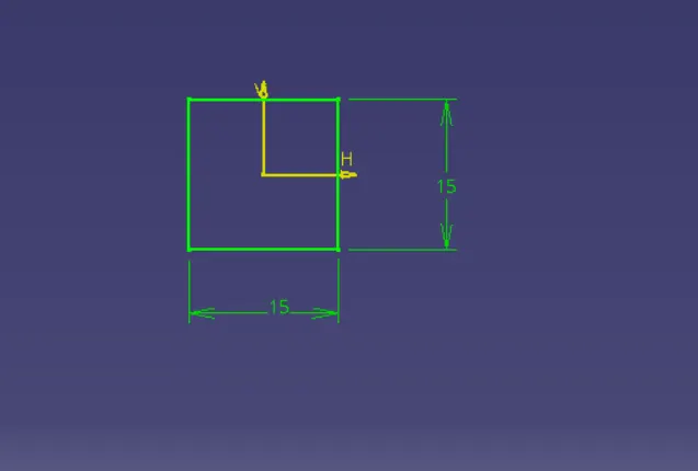
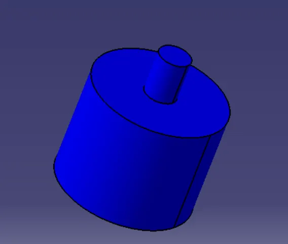
- Now make plane on top face of pad and make a circle.
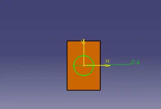
- Pad it and body 3 is ready.
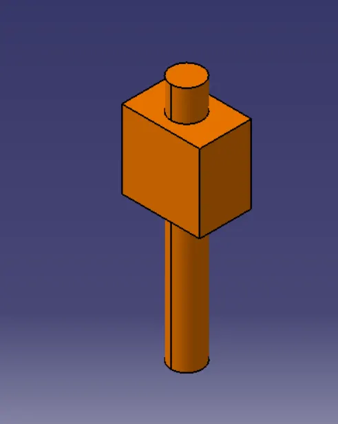
FOR BODY-4
- Draw a xketch as shown below
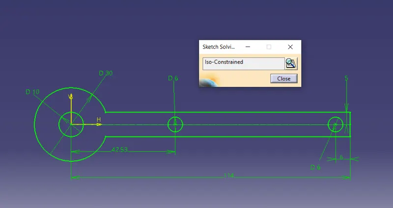
- Now use multi-pad and body-4 is ready.
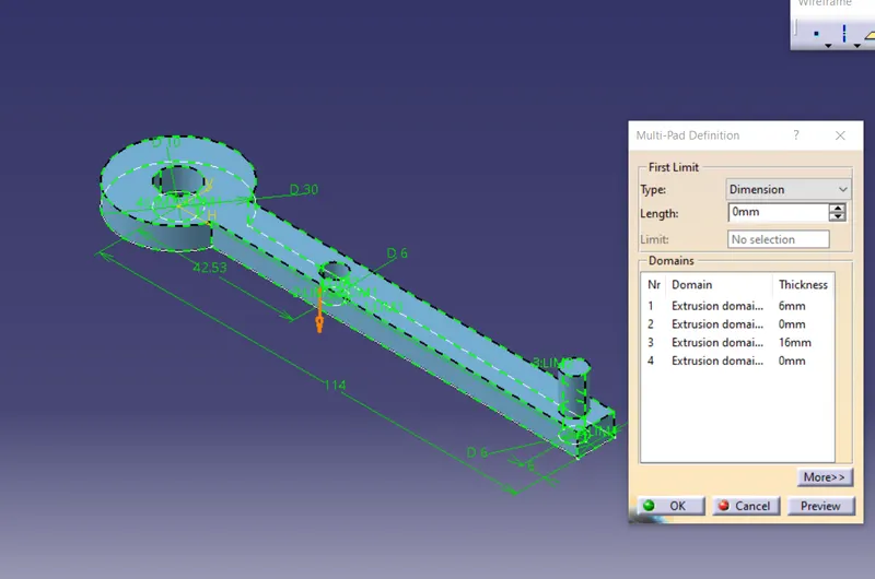
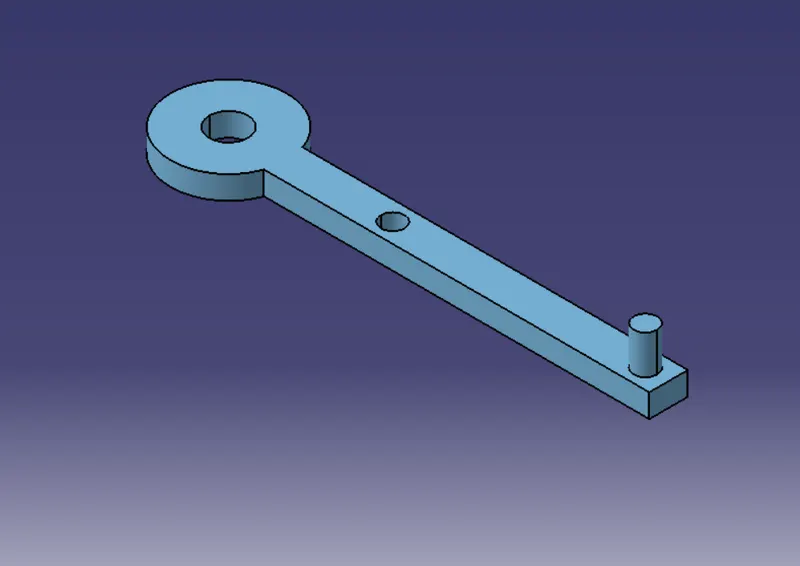
FOR BODY -5
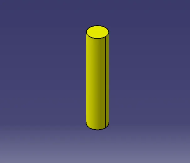
- Draw a circle of D= 10mm and pad it 50 mm and body 5 is also ready.
Assembly of quick return mechanism
Since we have made all 5 parts, now we will asemble it.
- Open assembly workbench and inerts all 5 parts.
- Now make a new part(Skeleton) and make a reference point.
- Use publication tool and publish all plane and point.
- Now i have make a reference axis in all 5 parts and publish all plane reference axis and point.
Now we will start assembly part.
- Fix the reference point of reference skeleton.
- Coincidence reference axis of body 2 and point of skeleton reference.
- Coincidence reference axis of body 1 and references axis body 2.
- Coincidence reference point of body 3 and reference Axis 2 of body 4
- Coincidence reference point of body 5 and reference axis of body 4
- Now use contact constraint to constrain body 5 and body 1
- Offset= -20 mm body 3 xy plane from body 1 zx plane.
- Offset= 0 mm body 1 yz plane and body 3 yz plane.
- Offset 7.5 mm body 3 xy plane from body for xy plane.
- Offset -7.5mm body 3 xy plane from body 1 xy plane.
- Offset -19 mm body for xy plane from body 5.
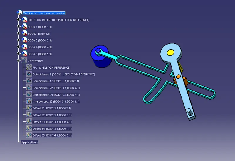
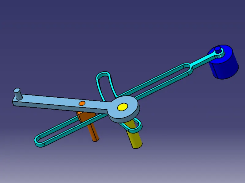
IMAGES OF ASSEMBLY OF QUICK RETURN MOTION MECHANISM
DRAFTING OF QUICK RETURN MOTION MECHANISM
BODY-1
BODY-2
BODY-3
BODY-4
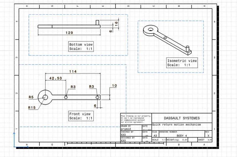
BODY-5
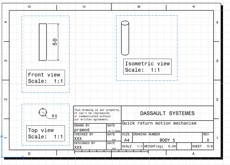
FINAL ASSEMBLY
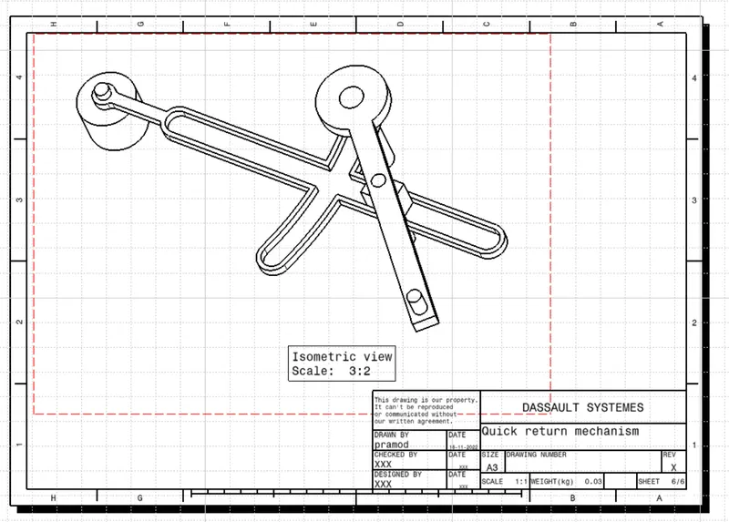
FOR CV JOINTS
Now we will make solid parts of CV joints.
BODY-1
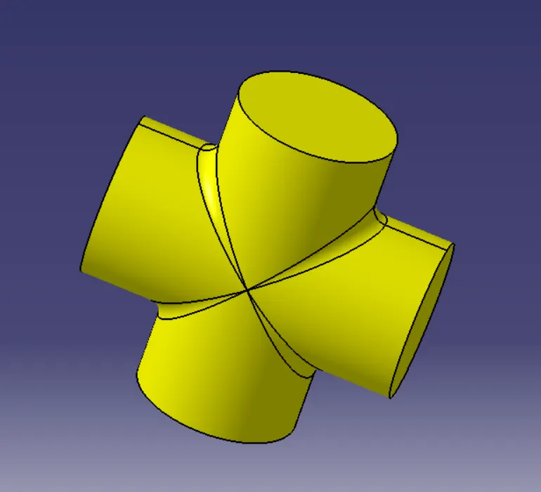
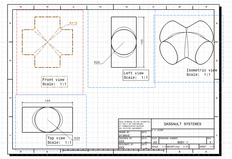
- Make a circle of D=50 mm and pad it 100mm.
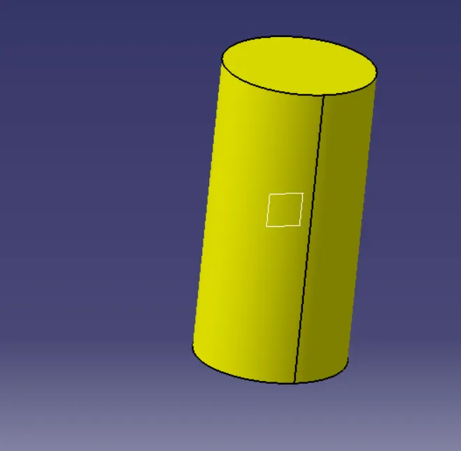
- Now select the plane(zx) shown in above pic and draw again circle of d=50mm and pad it 100m.
- Use add operation and apply fillets.
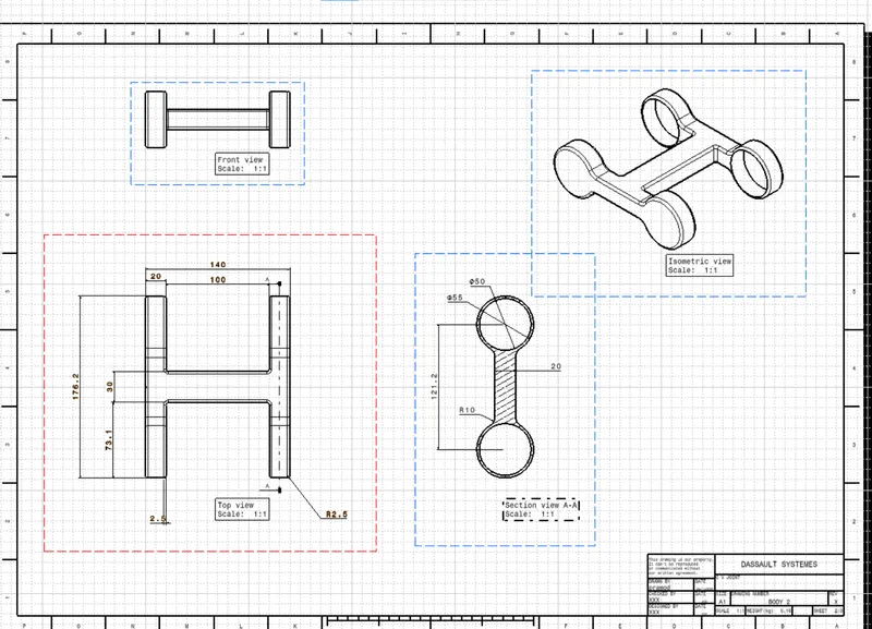
FOR BODY -2
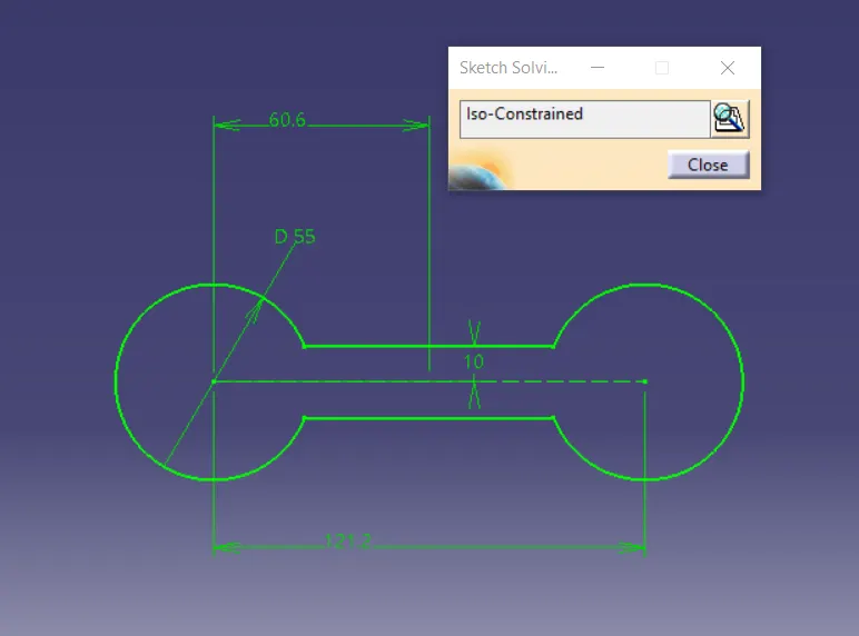
- Draw a sketch as shown in below image and pad 20 mm
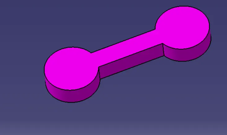
- Now we will make a hole on both sides
- make circle of D= 50mm and pad 17.5mm in down direction and use remove command.
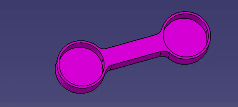
- Offset a plane 50mm and Mirror this part.
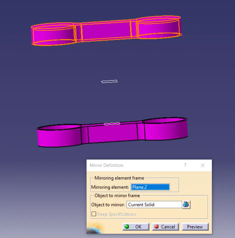
- now we make centre part
- draw a sketch a shown below.
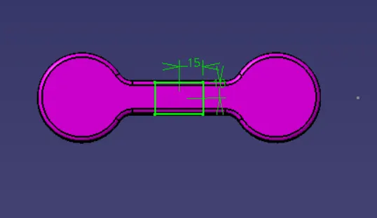
- Pad it and use add operation,
- Apply the fillets and our 2nd body is ready
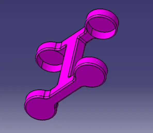
BODY-3
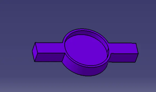
- Make a sketch as shown below and pad it 15mm.
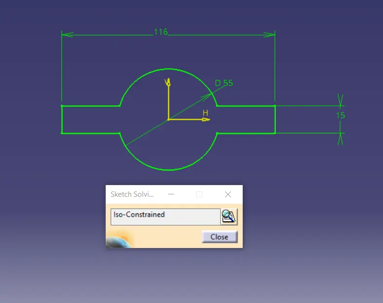
- now we will provide circular cut/hole.
- Draw a circle D=50 mm , pad it 7mm.
- now use remove operation.
- Next we will make corner side parts.
- make a sketch as shown below.
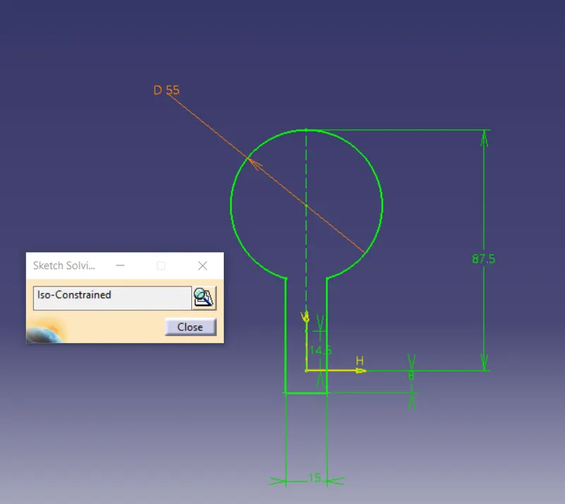
- Pad it 15mm.
- Now for circluar hole , make a circle of D=50mm and pad it 7mm and use remove opertaion.
- Now mirror it.
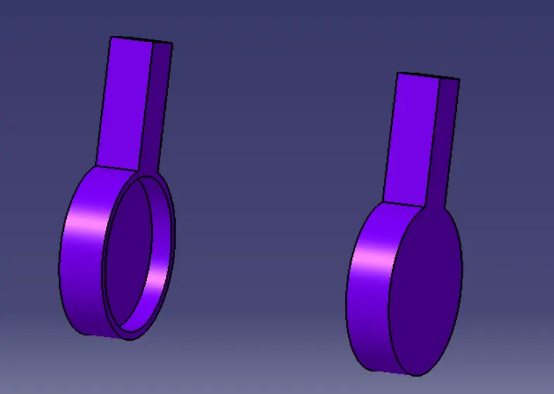
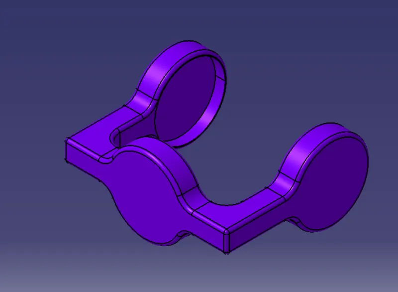
- now use add opertion and apply fillets
Image of body 3
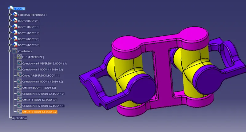
Assembly of CV JOINT
Since we have made all 3 parts, now we will asemble it.
- Open assembly workbench and inerts all 3 parts and since body 1 and 3 are used two times insert them twice..
- Now make a new part(Skeleton) and make a reference point.
- Use publication tool and publish all plane and point.
- Now we will make reference axis in all parts and publish all plane reference axis and point.
Now we will start assembly part.
- Fix the reference point of reference skeleton.
- Coincidence reference point of body 2 and point of skeleton reference.
- Coincidence reference axis of body (1.1) and references axis body 2.
- Offset 70 mm zx plane of Body (1.1) from yz plane of skeleton reference.
- Coincidence reference Axis 2 of body 2 and reference Axis 2 of (body 1.2)
- Offset 0mm body(1.1 ) zx plane and body(1.2 )yz plane.
- Coincidence reference Axis 1of body (3.1) and reference axis 1 of body (1.2)
- Offset at 0mm zx plane of Body ( 1.2) from zx plane of body (3.1)
- Coincidence reference Axis 1 of body (3.2) and reference Axis 2 of body (1.1)
- Offset 0 mm yz plane of body (1.1) from ZX plane of body (3.2).
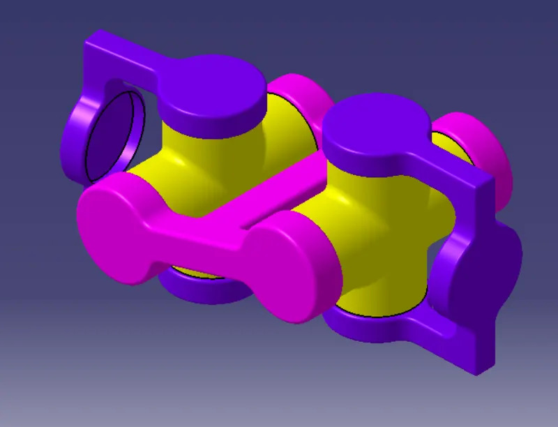
IMAGE OF CV JOINT
DRAFTING OF CV JOINT
FOR BODY-1
FOR BODY-2
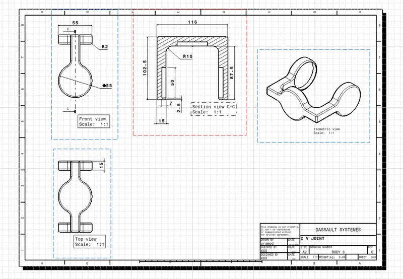
FOR BODY 3
FOR ASSEMBLY