Week 10- Assembly Workbench
Assembly Workbench
Aim: - The aim of this report is to work on the part creation, assembly, and drafting of the quick return motion mechanism and CV joint in CATIAV5 (Computer-aided three-dimensional interactive application).
Objective: -
- To explore the assembly workbench and its different features.
- Creation of parts with proper dimension and required assumptions with proper assembly constraints.
- Creation of drafting for the parts and assembly as given in the challenge.
Theory: -
- Quick return motion mechanism: -
A quick return mechanism is an apparatus to produce a reciprocating motion in which the time taken for travel in return stroke is less than in the forward stroke. It is driven by a circular motion source (typically a motor of some sort) and uses a system of links with three turning pairs and a sliding pair.
- Whitworth Quick Return Mechanism.
- Crank and Slotted Link Mechanism and.
- Hydraulic Drive.
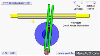
figure 01: - Example of the quick return mechanism
2. CV joint: -
Constant-velocity joints (also known as homokinetic or CV joints) allow a drive shaft to transmit power through a variable angle, at constant rotational speed, without an appreciable increase in friction or play. They are mainly used in front-wheel drive vehicles. Modern rear-wheel-drive cars with independent rear suspension typically use CV joints at the ends of the rear axle half shafts and increasingly use them on the drive shafts. The two most commonly used types of CV joints are the ball-type and tripod-type. In front-wheel drive vehicles, ball-type CV joints are used on the outer side of the drive shafts (outer CV joints), while the tripod-type CV joints are mostly used on the inner side (inner CV joints).
Constant-velocity joints are protected by a rubber boot, a "CV gaiter", usually filled with molybdenum disulfide grease. The six spheres are bounded by an anti-fall gate that prevents the spheres from falling when the shafts are perfectly aligned. Cracks and splits in the boot will allow contaminants in, which would cause the joint to wear quickly as grease leaks out. (Parts in contact would not get proper lubrication, small particulates would cause damage and scratching, while water ingress causes metal components to rust and corrode.) Wear of the boot often takes the form of small cracks, which appear closer to the wheel, because the wheel produces most of the vibration and up and down motions. Cracks and tears in the areas closer to the axle are usually caused by external factors, such as packed snow, stones, or uneven rocky off-road paths. Aging and chemical damage can also cause boot failure.
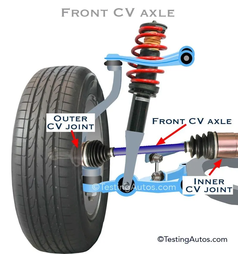
figure 02: - Example of CV joint
3. Procedure followed: -
The steps followed while assembling the created parts are as follow: -
Step 1: - At the very first, make one zero reference point and then fix it. The whole assembly will be based on this point. If one moves this point then the whole assembly will be moved.
Step 2: - Make reference elements for different parts and simultaneously constraint them together.
Step 3:- Use different constraints in order to assemble parts. The most frequently used constraints are co-incidence, fix, offset, etc.
Step 4: - In order to check whether the assembly is proper or miss-aligned, one can use explode command.
Step 5: - At last, one can publish all the references used. So that they are easy to search and modify.
All assemblies and their drafting is attached below.
Conclusion: -
- One should never reposition any part file after completing the whole assembly because it can lead to errors in the assembly file.
- One can use the explode command given in the assembly workbench in order to check whether the assembly is proper or miss-aligned.
- One should not use the symmetry option in case of 2 or 3 copies of the same part that has to be assembled because industries generally do not use it.
- Fixing zero reference points and then fixing the whole assembly on it is one of the important steps involved while assembling parts.