Week 10- Assembly Workbench
AIM :
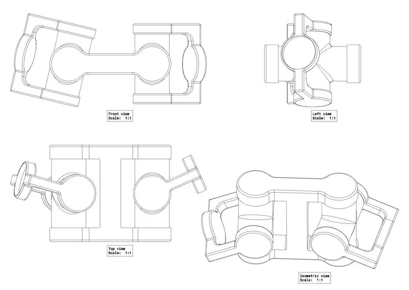
2D diagrams of the components and you will have to first create the individual part files and then create a complete assembly of those part files in the assembly workbench.
MODEL DRAWING 1
INTRODUCTION OF QUICK RETURN MECHANISUM :
A quick return speed mechanism is used in the shaper and slotter machine in which the circular motion is converted to reciprocating motion so that the slider moves forward and backward.
In the shaper and slotter machine, a quick return motion mechanism converts circular motion into reciprocating motion, allowing the slider to move forward and backward. The cutting process occurs in the forward motion, but there is no corresponding cutting in the reverse direction. A quick return mechanism is a device that generates a reciprocating motion in which the return stroke takes less time than the forward stroke. It uses a system of links with three turning pairs and a sliding pair to be driven by a circular motion source (usually a motor of some sort). With an offset crank, a quick-return mechanism is a subclass of a slider-crank linkage.
Machines with quick return mechanisms can be found all over the engineering industry. Below are the applications of a quick return mechanism.
- Shaper
- Screw press
- Power-driven saw
- Mechanical actuator
- revolver mechanisms
- rotary combustion internal engine
- air compressor
- mechanical cutter.
The following are the key components of a quick return mechanism:
- Crank: The crank is attached to the pinion wheel or motor and rotates at a constant angle.
- Slider and Slotted Bar: The slider pivots at the crank’s end. This slider is free to move within the slotter bar. This component is responsible for converting the crank’s circular motion into the slotted bar’s oscillating action.
- Connecting rod: The connecting rod’s job is to transform the slotted bar’s oscillating action into reciprocating motion.
- Ram: The ram reciprocates along the stroke line in a horizontal direction.
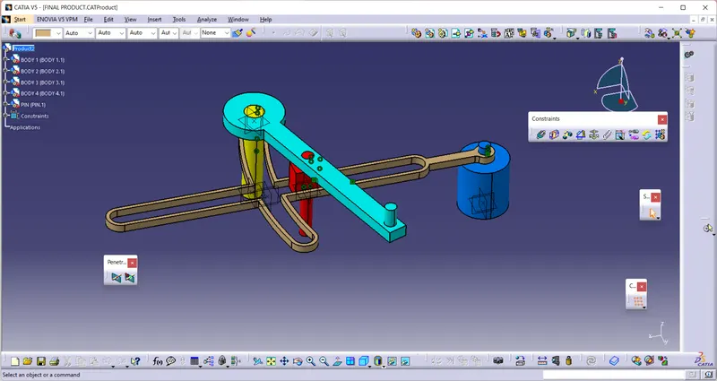
So our Aim is to creat this Mechanisum First we Need To Creat Parts Of this Mechanisum
First Part
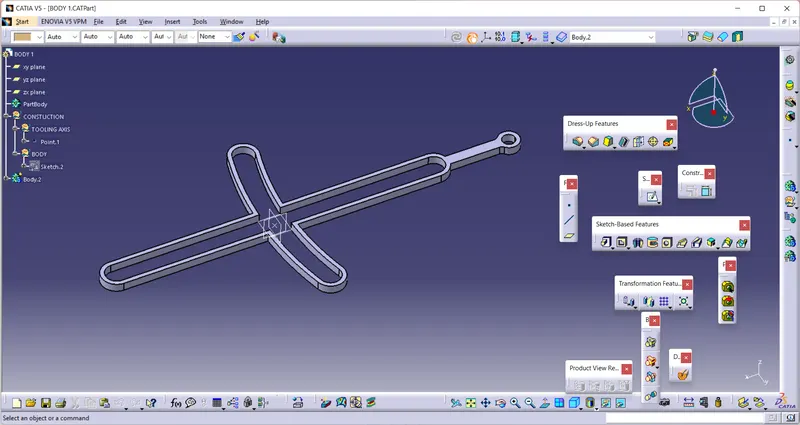
DFRAFTING OF THIS PART
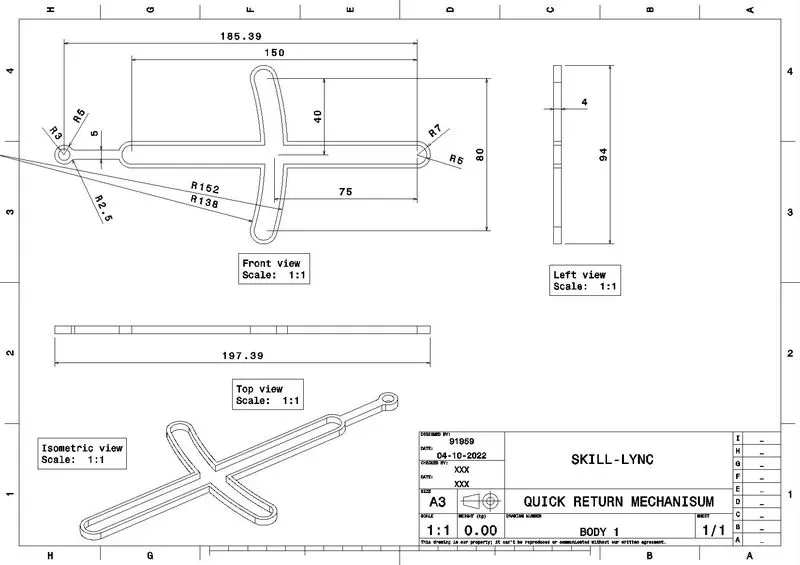
SECOND PART
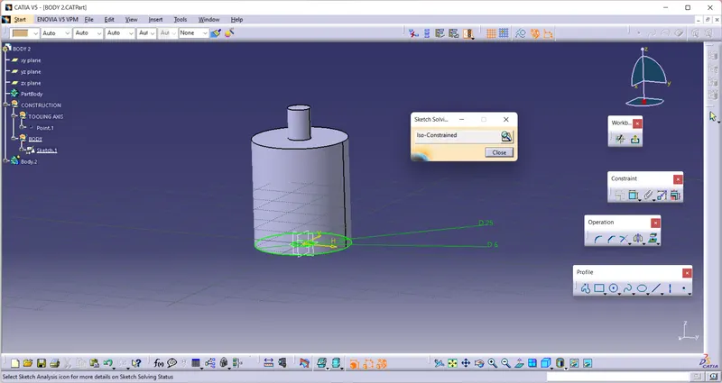
DRAFTING OF THIS PART
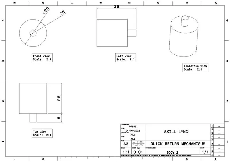
THIRD PART
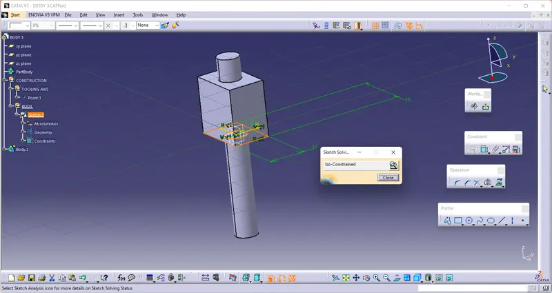
DRAFTING OF THIS PART
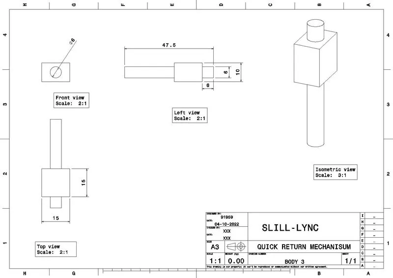
FOURTH PART
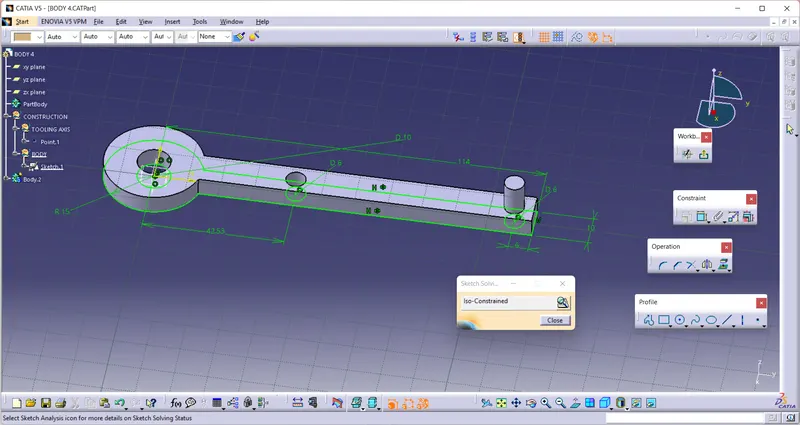
DRAFTING OF THIS PART
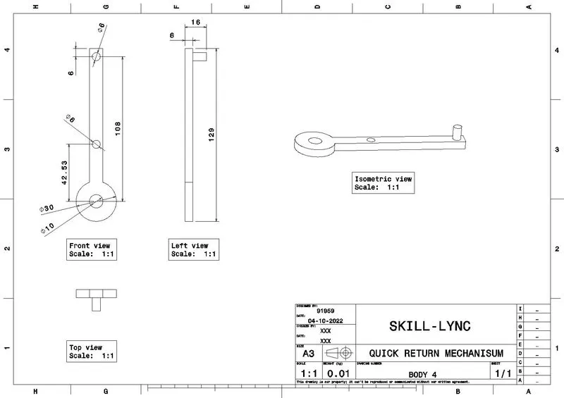
FIFTH PART
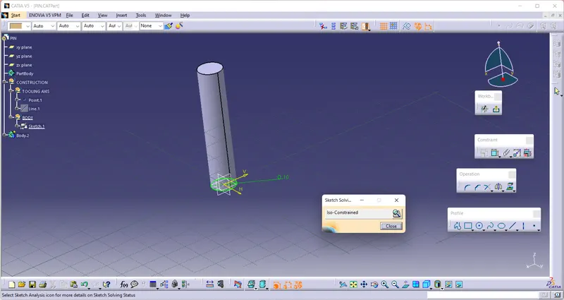
DRAFTING OF THIS PART
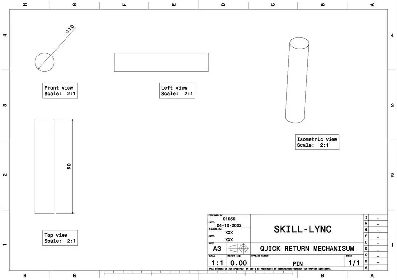
FINAL PART
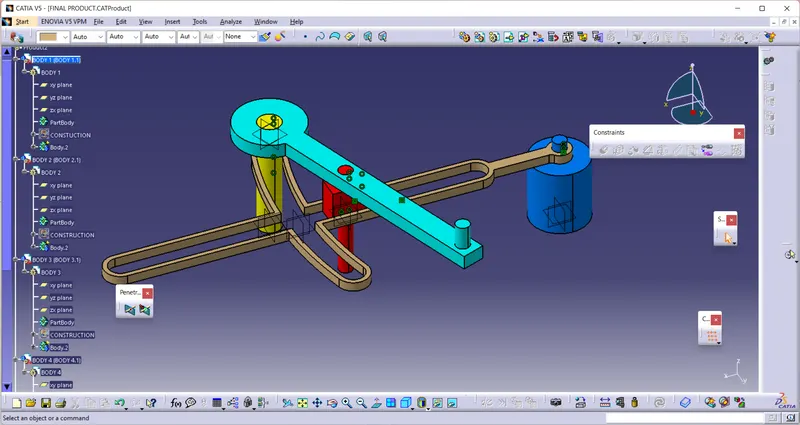
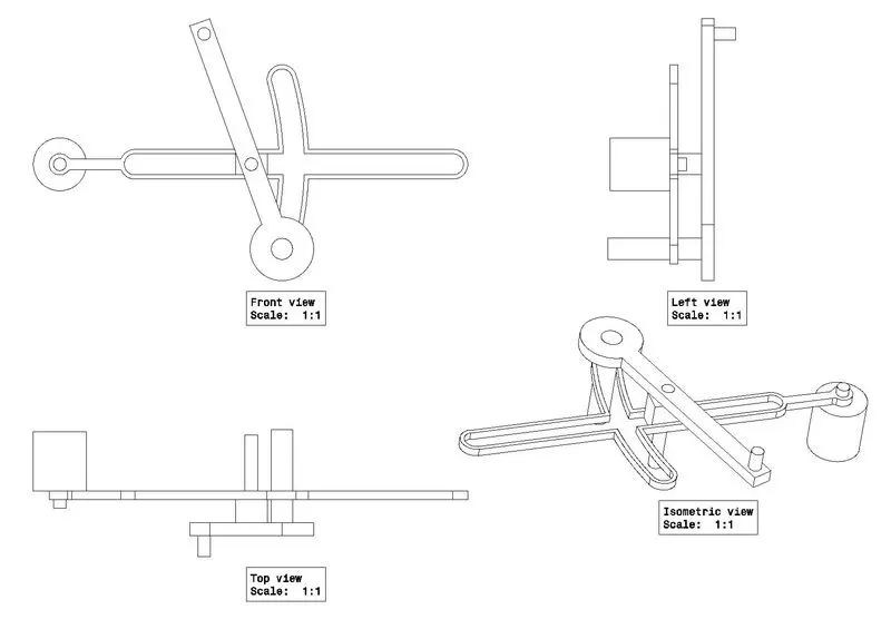
FINAL DRAFTING
MODEL DRAWING 2
CV JOINT
Constant velocity (CV) joints are mechanical power transmission components that provide rotational power at various angles. They provide the same output velocity in relation to the input velocity, independent of the angle they are operated at. This contrasts with most other joints, which may provide a different output velocity at sharper angles even with the same input velocity.
A CV joint may operate efficiently up to 80° deviation from a straight line. By operating in pairs, larger angles are possible. The effective life of a CV joint will generally be shortened as joint angle increases. CV joints are effective for high velocity power transmission where operating angles are acute. CV joints tend to be heavier and more expensive than universal joints and tend to fail more quickly.
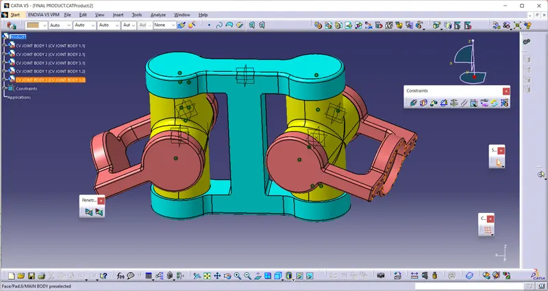
So our Aim is to creat this Mechanisum First we Need To Creat Parts Of this Mechanisum
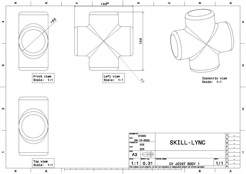
FIRST PART
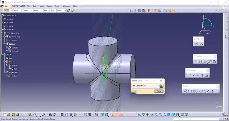
DRAFTINF OF THIS PART
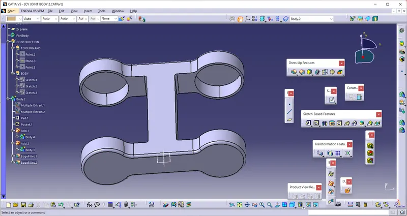
SECOND PART
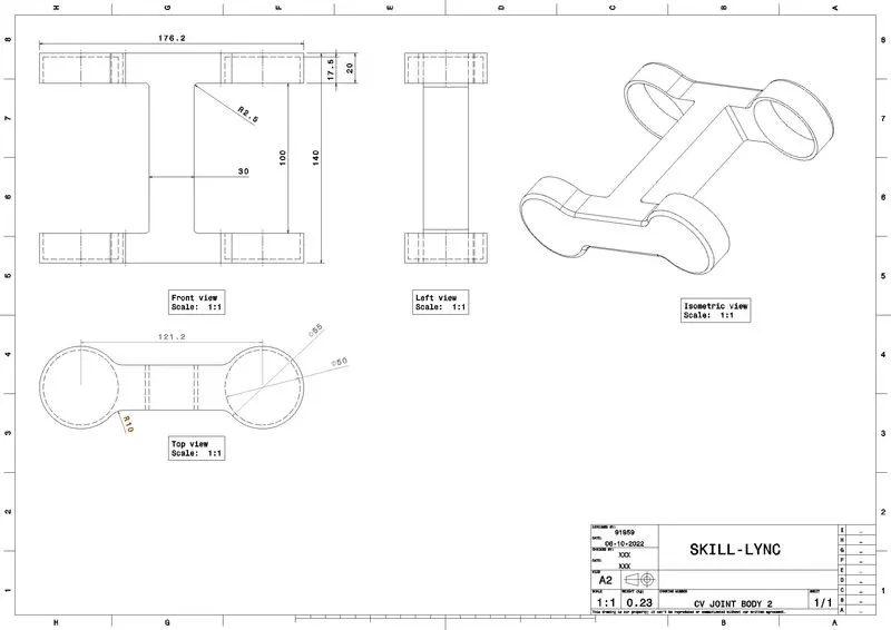
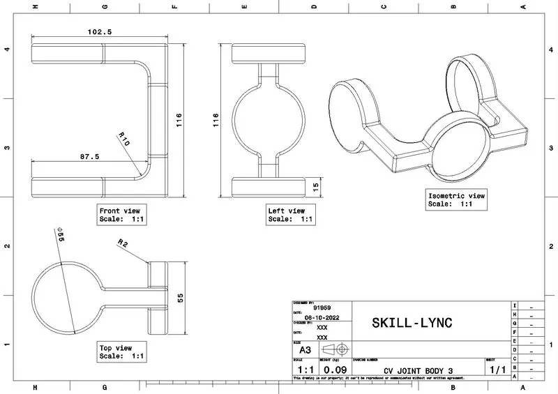
DRAFTING OF THIS PART
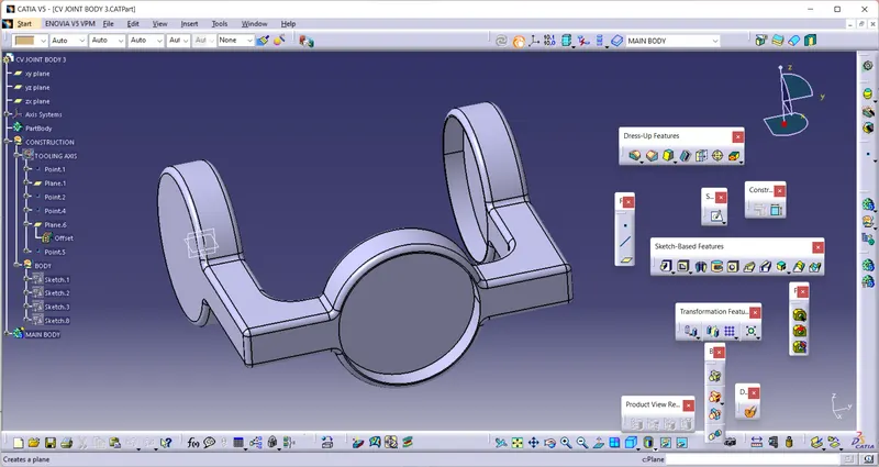
THIRD PART
DRAFTING OF THIS PART
FINAL PRODUCT
DRAFTING OF THIS PART