Week 10- Assembly Workbench
ASSEMBLY WORKBENCH
To design various parts of a component from the given 2D drawing and assemble them together to get the final product then create the 2D drawing by drafting tools and conclude the result.
- First step is to analyze the input 2D drawing and understand the details given on it and check for all the dimensions, if not there assume them with respect to the sketch and then arrange them in a ordered manner.
- Make a clear understand about the steps to be followed to create the various parts of the drawing and proceed with it by creating a ISO constrained positioned sketch.
- Convert the sketch into 3D or solid body by pad tool and by using various options available in the toolbar.
- Use the Boolean operations to join various parts to get the solid body and save it.
- If we have identical component used in different positions of the product, in such case we can directly offset the sketch or mirror the solid body or make a duplicate copy by translating method.
- After creating all the various parts of the product then assemble them by using assembly design work bench.
- Assembly can be done by calling the individual saved parts by using existing component option in the tool bar then manipulate them as per the required position and constraint them with respect to the degree of freedom (axis, point, face, dimension, angle, etc) of each part and arresting the unwanted.
- Once the assembly is done check for the degree of freedom of each part by manipulating them into different locations and update it.
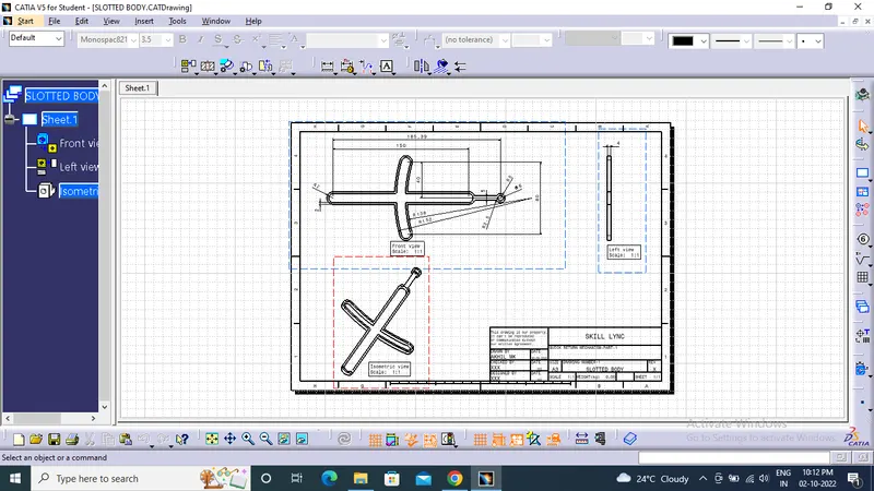
- Drafting of the designed component can be done by using drawing work bench by calling various orientations of the it and do appropriate operations like projection view , sectioning, dimensions, positioning, axis, balloons, etc.
- Frames and title block can be added by changing the view into sheet background and finally change it into working view.
OUTPUT SCREENSHOT OF DRAWING-1
Quick Return Mechanism
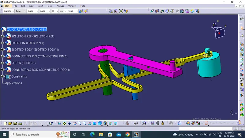
A Quick Return Mechanism is a mechanical assembly to create a reciprocating motion which is so designed to reduce ideal time required for return stroke. It is a four bar mechanism comprised of fixed link, crank, pin sliding in the slot and a sliding pair.
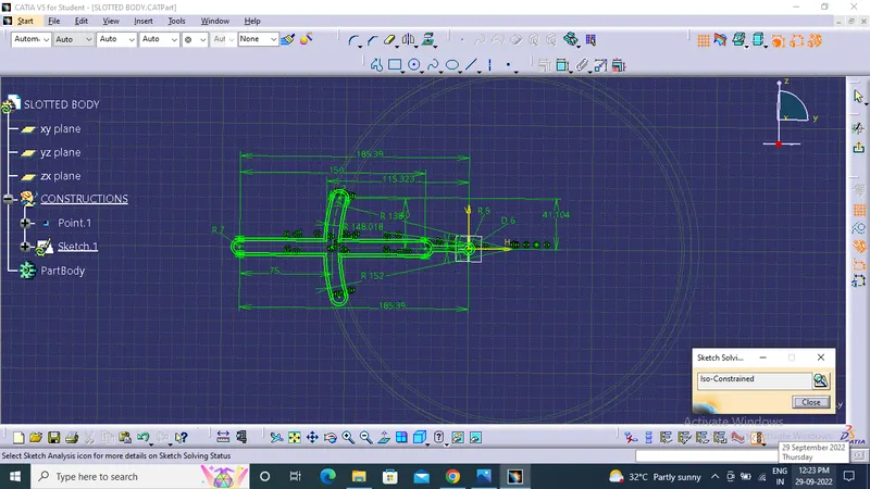
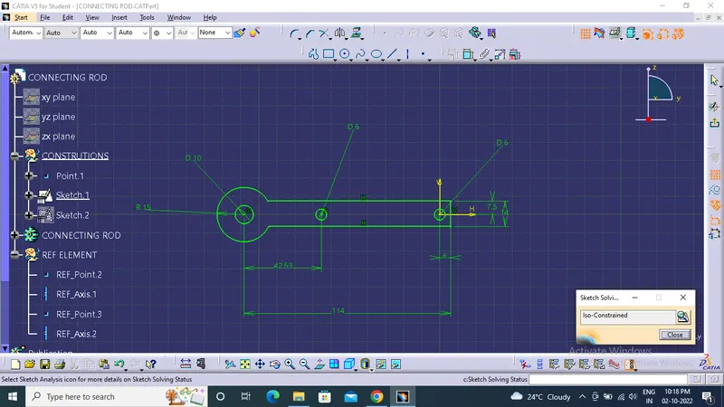
ISO CONSTRAINED POSITIONED SKETCH OF QUICK RETURN MECHANISM
SOLID BODY COMPONENTS OF QUICK RETURN MECHANISM
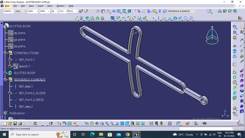
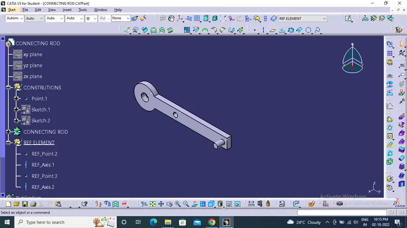
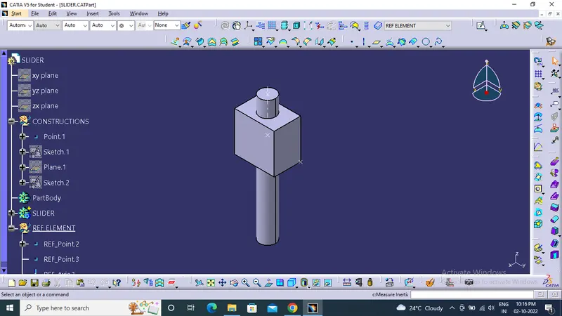
ASSEMBLED COMPONENTS OF QUICK RETURN MECHANISM
DRAFTING OF COMPONENT OF QUICK RETURN MECHANISM
DRAFTING OF ASSEMBLED QUICK RETURN MECHANISM
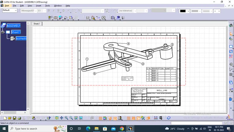
OUTPUT SCREENSHOT OF DRAWING-2
Constant-velocity joints (CV JOINTS)
Constant-velocity joints (also known as homo kineticor CV joints) are mechanical joints which allow a drive shaft to transmit power through a variable angle, at constant rotational speed, without an appreciable increase in friction or play. They are mainly used in front-wheel drive vehicles. Modern rear-wheel drive cars with independent rear suspension typically use CV joints at the ends of the rear axle half shafts and increasingly use them on the drive shaft.
ISO CONSTRAINED POSITIONED SKETCH
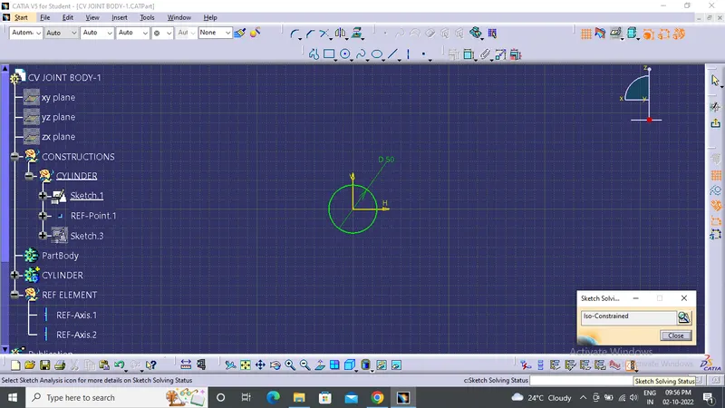
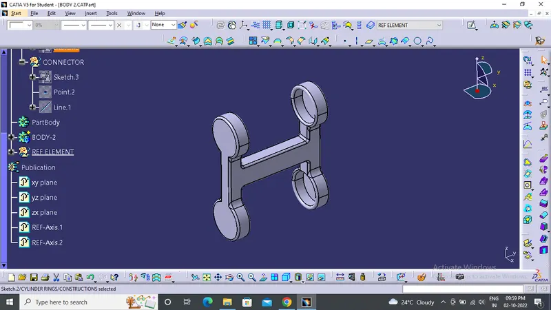
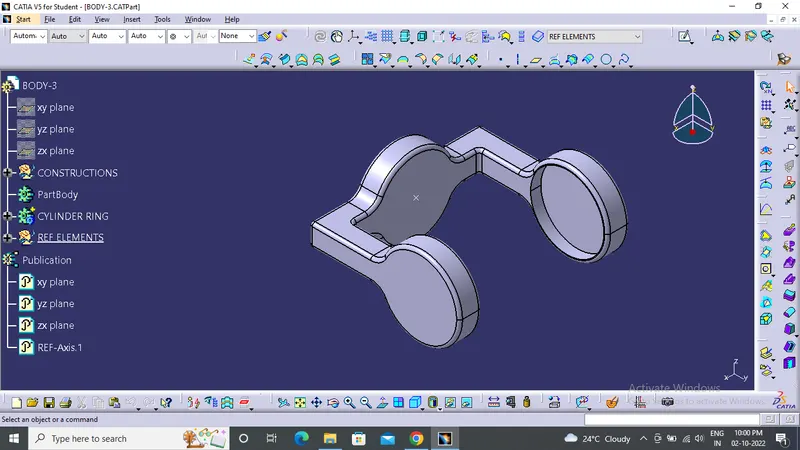
COMPONENTS OF CV JOINTS
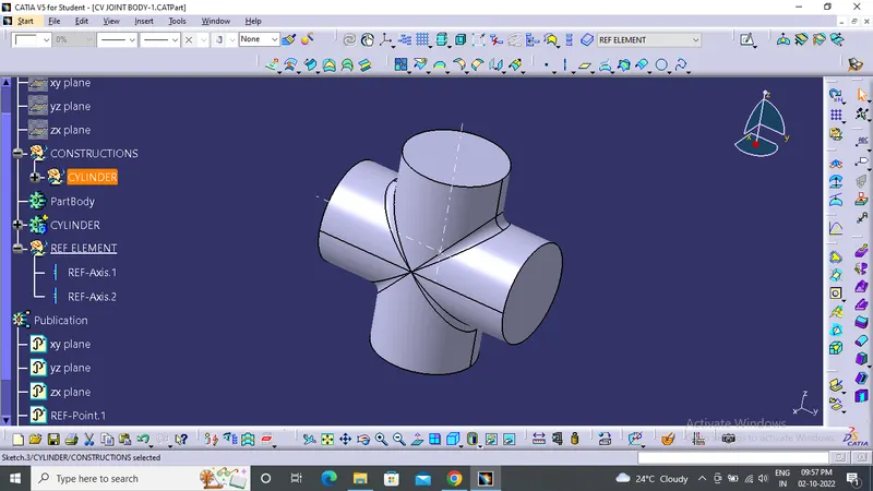
ISO CONSTRAINED POSITIONED SKETCH
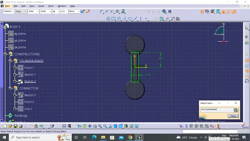
COMPONENTS OF CV JOINTS
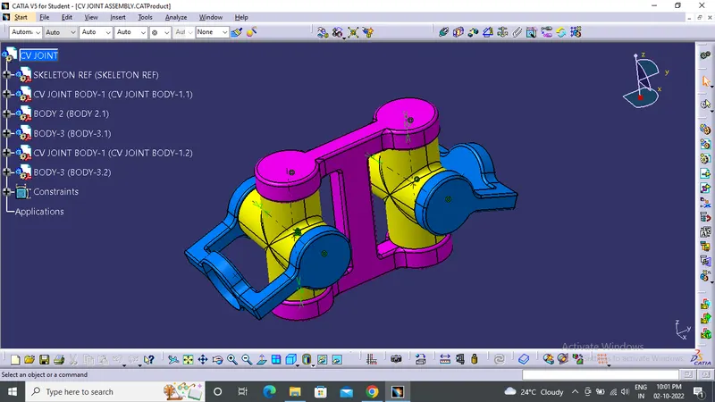
ASSEMBLED CV JOINTS
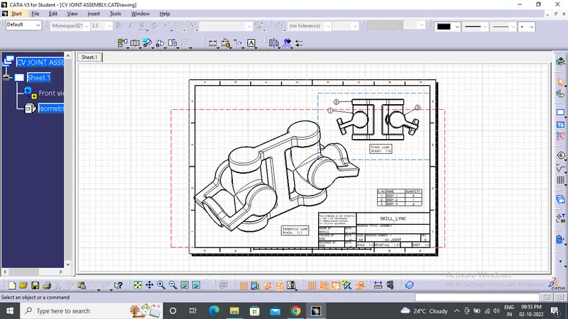
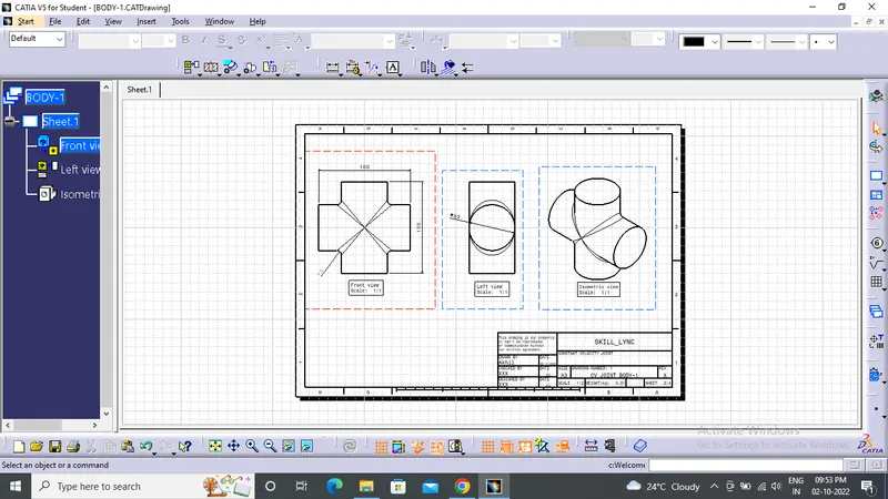
DRAFTING OF COMPONENT OF CV JOINT
DRAFTING OF ASSEMBLED CV JOINT