Week 10- Assembly Workbench
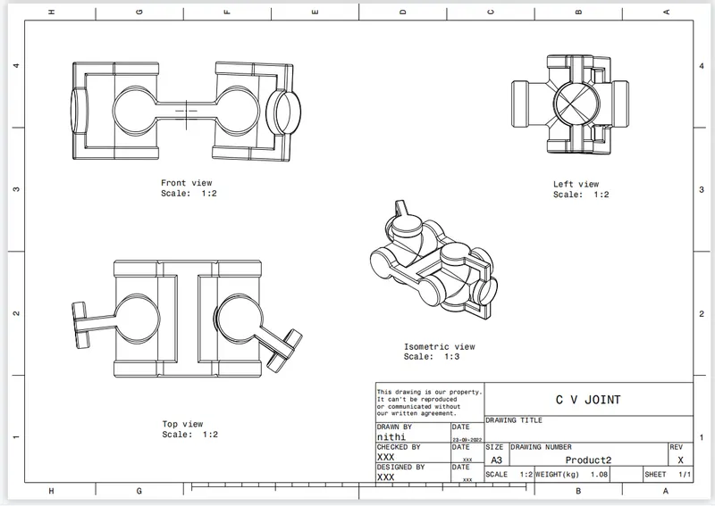
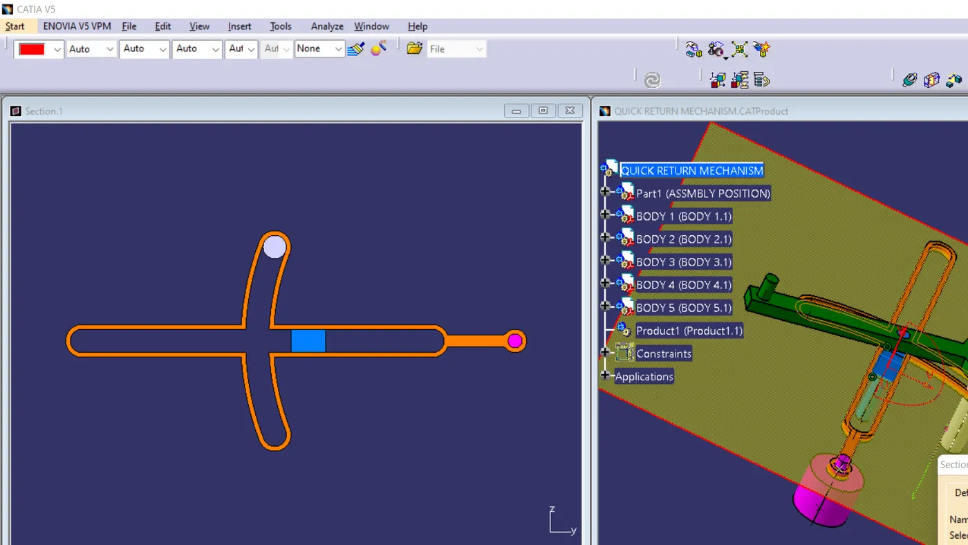
MODEL 1 FIG
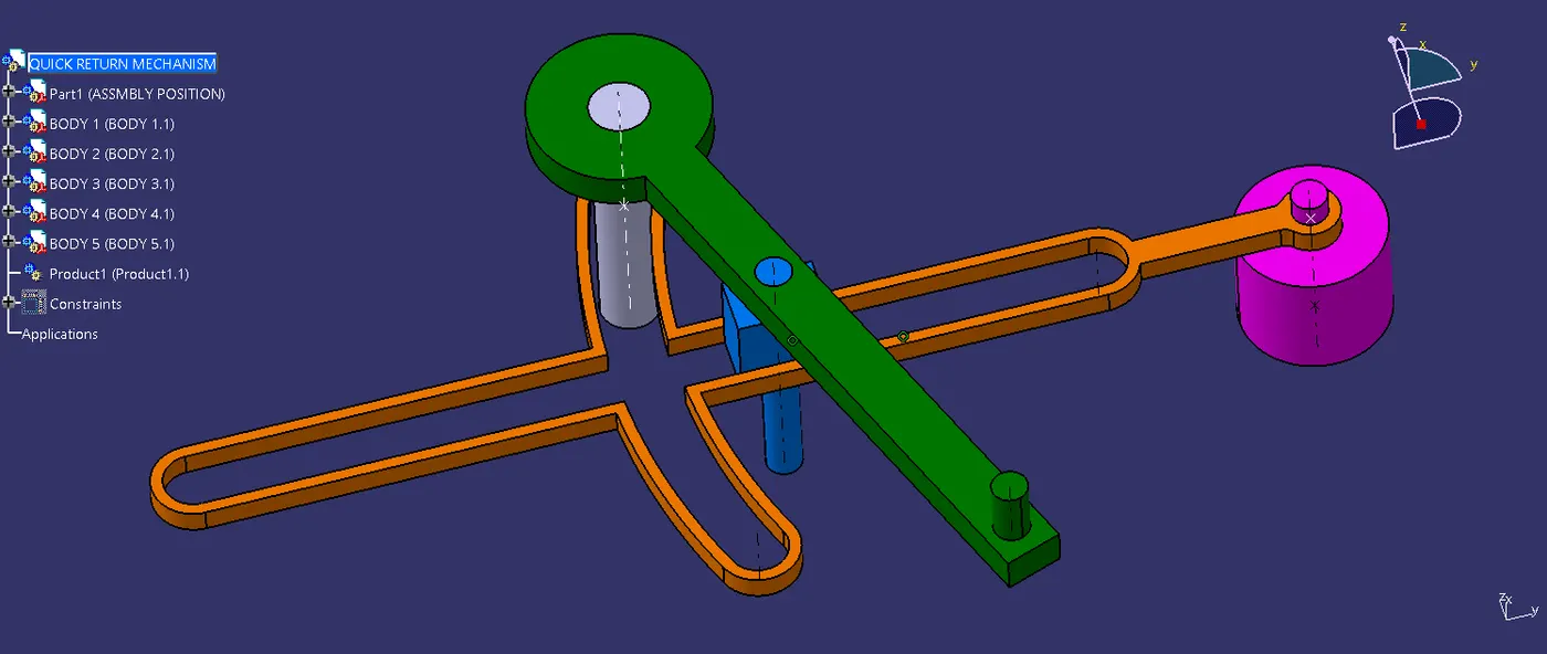
MODEL 2 FIG
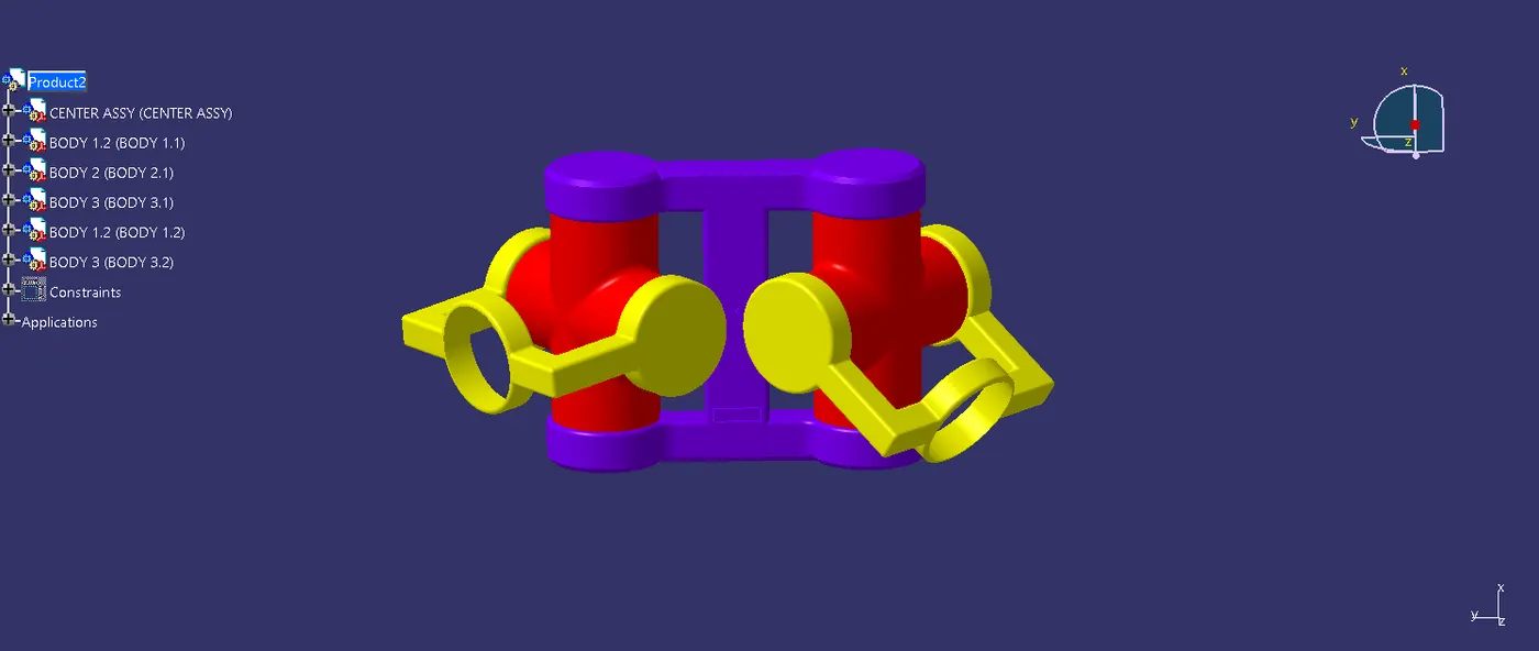
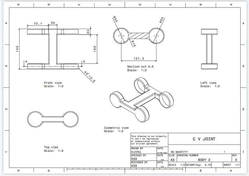
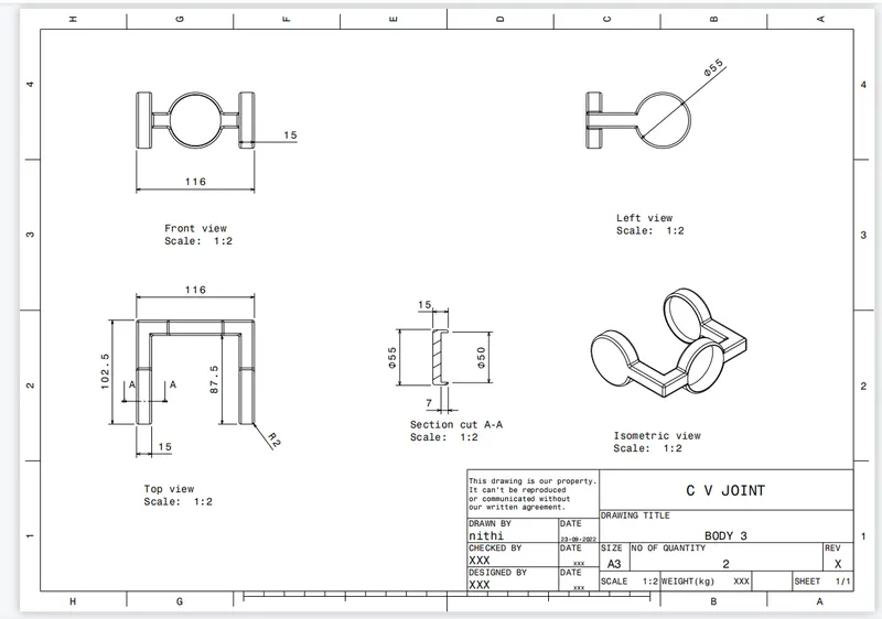
without permission, I increased the length of one side of the spider part mentioned in the red color . the length of the spider was 100 and the holder's inner distance was also 100 (in the blue color) . the holder has two pockets on both sides to attach the spider in it. but the length of both parts is 100 so that the spider won't attach to the pockets. so that I increased the length of the joining portion. Was that correct or not? please tell me in the remarks
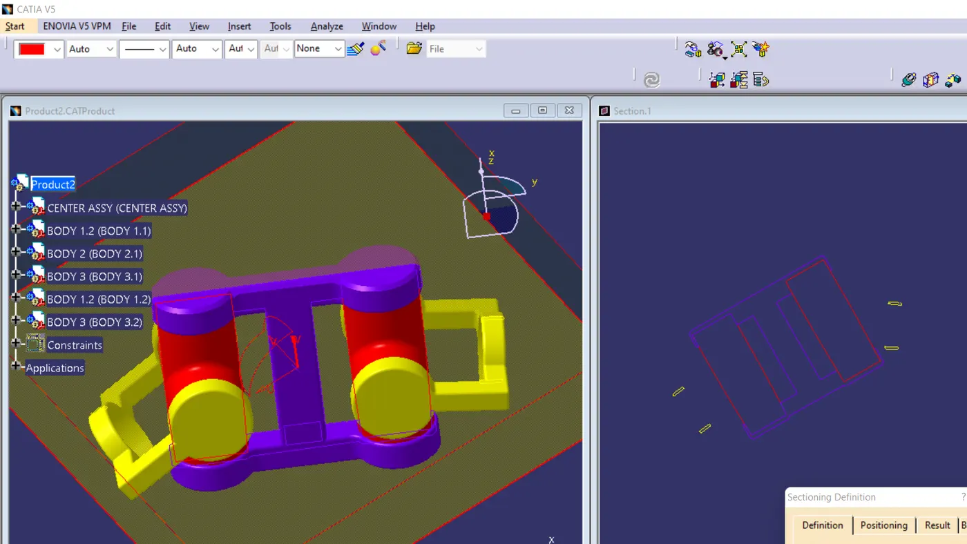
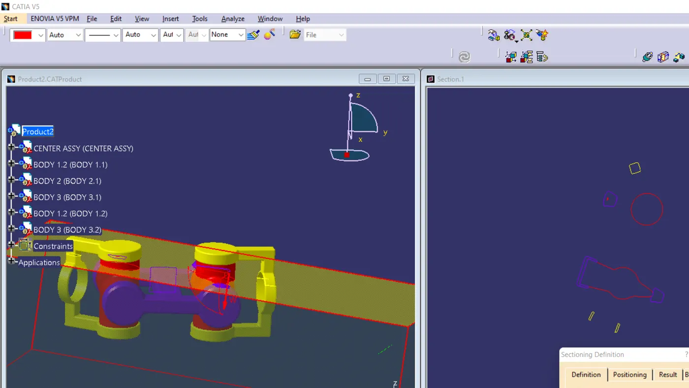
REPORT
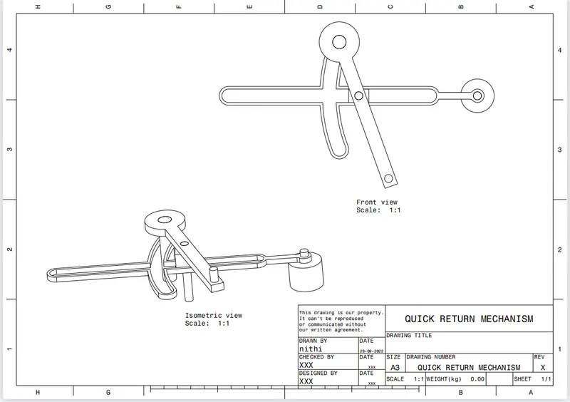
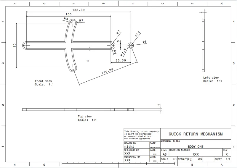
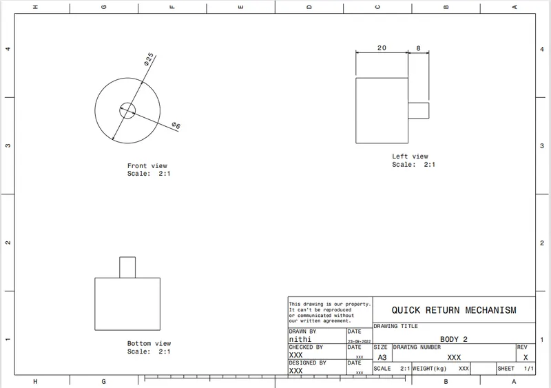
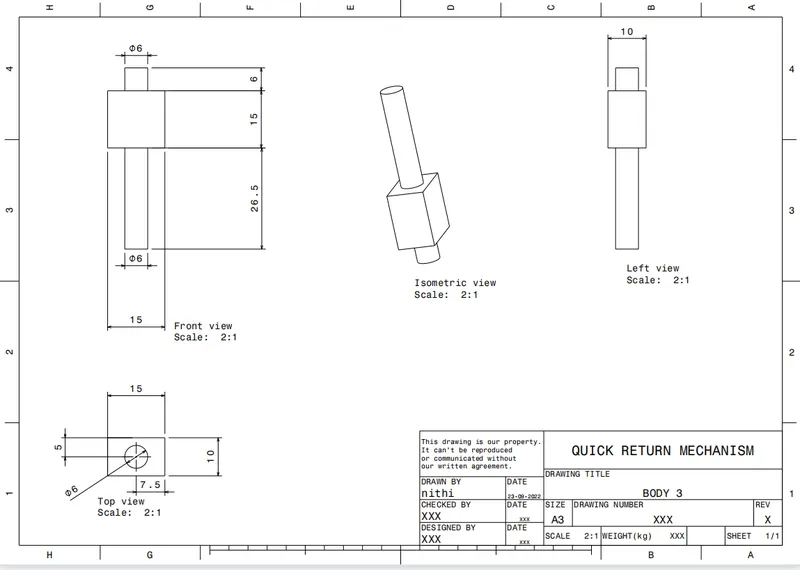
the first step is creating the individual parts of the given component according to the measurements provided. then go to the assembly and add all the parts to the assembly part. after that publish all the axis and points which is used for the assembling then , first fix a component as a base .then with the help of the constraint tools attach all the part. after completing all this saved the file using the save management.
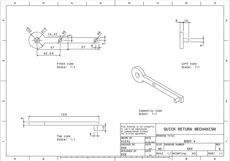
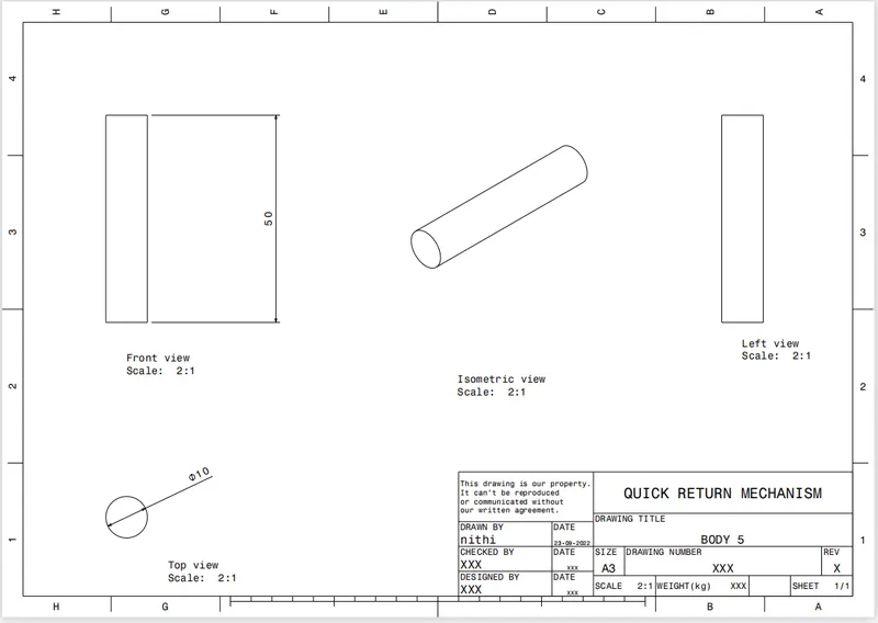
created all the draft images of the components and made a pdf of it.
model 2