Week 10- Assembly Workbench
CV JOINT
CREATING INDIVIDUAL PART BODIES:
BODY 1:-
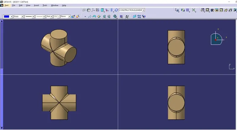
- First, create a sketch of 50 mm diameter and EXTRUDE.
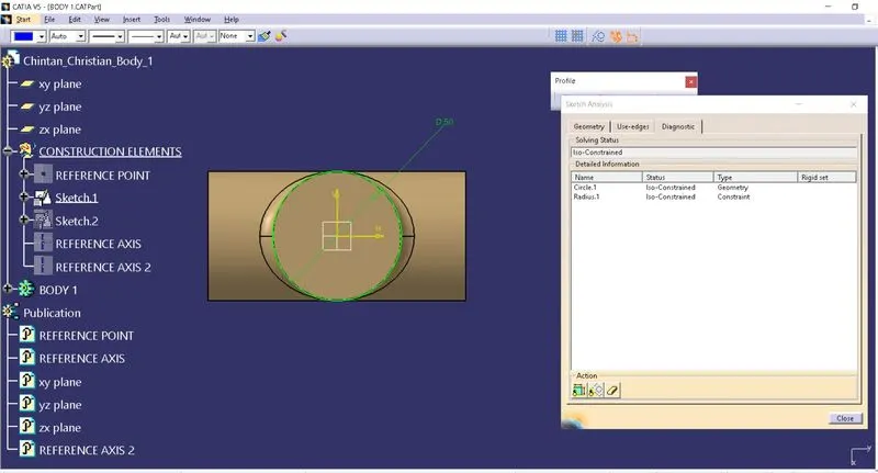
- Copy-paste same sketch at right angle plane and EXTRUDE
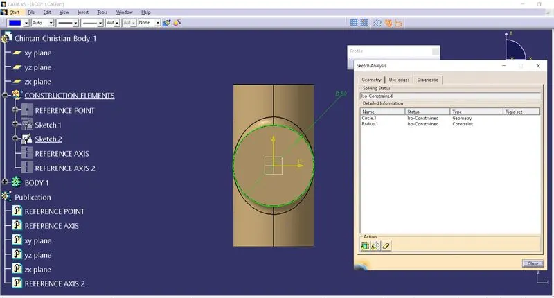
- Assemble those 2 extrudes using ADD Boolean operation. Apply fillet of 5 mm on edges.
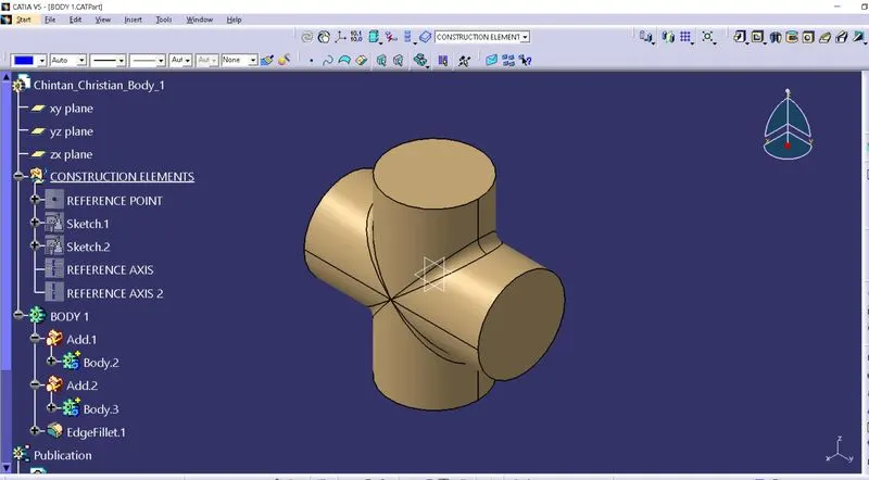
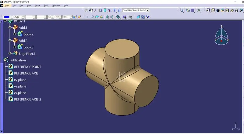
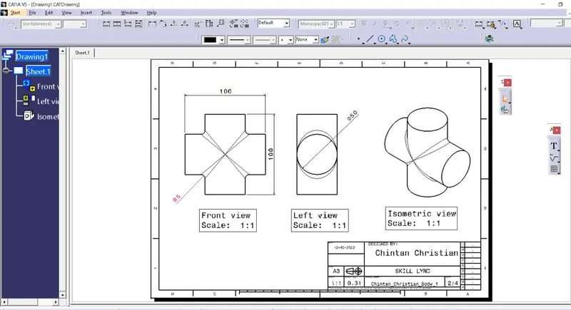
- Create drawing of the BODY 1 as per given file. Apply proper dimensions, style and add FRAME and TITLE BLOCK to it.
BODY 2:-
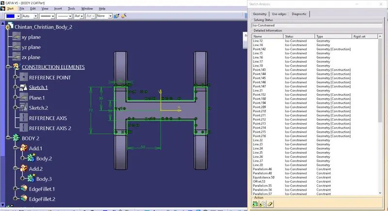
- First, create a sketch of I SECTION as shown in figure and EXTRUDE it about 20 mm.
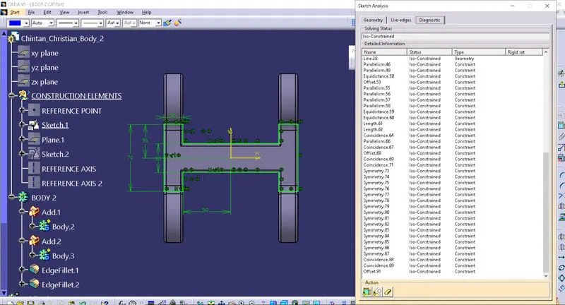
- Now, create sketch of circular base of 55 mm diameter and EXTRUDE Give it 2.5 mm SHELL THICKNESS.
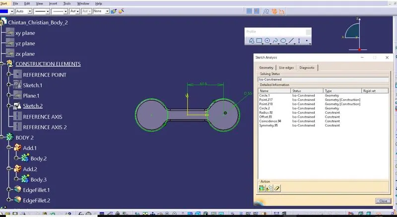
- MIRROR these circular base on 3 positions as shown in figure.
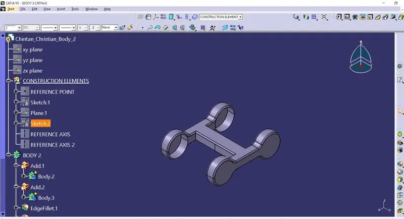
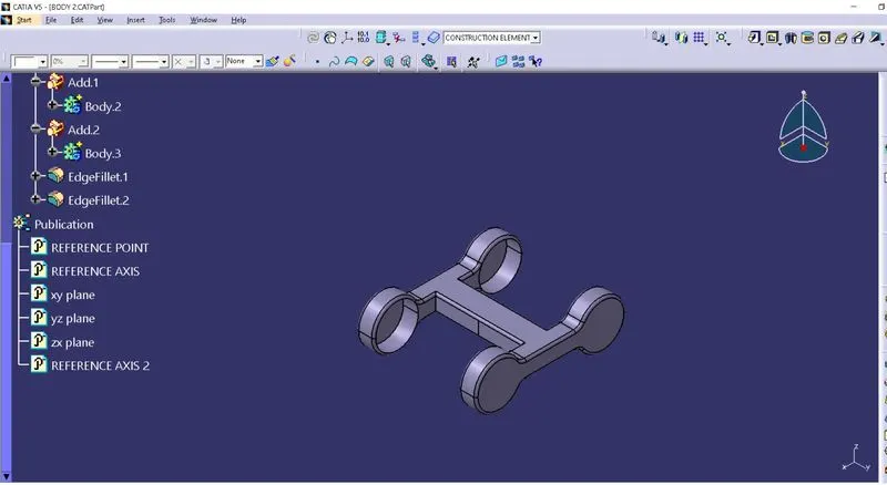
- Assemble these extrudes using ADD Boolean operation. Apply fillet of 2.5 mm on edges.
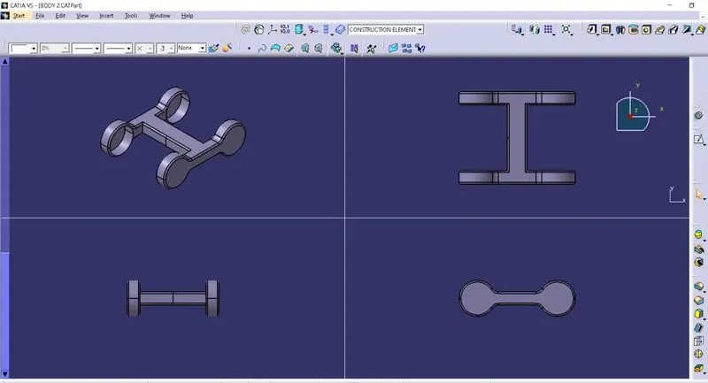
- Create drawing of the BODY 2 as per given file. Apply proper dimensions, style and add FRAME and TITLE BLOCK to it.
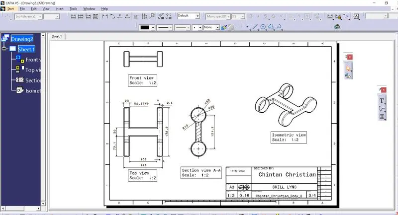
BODY 3:-
- First, create a sketch of BASE SECTION as shown in figure and EXTRUDE it about 15 mm.
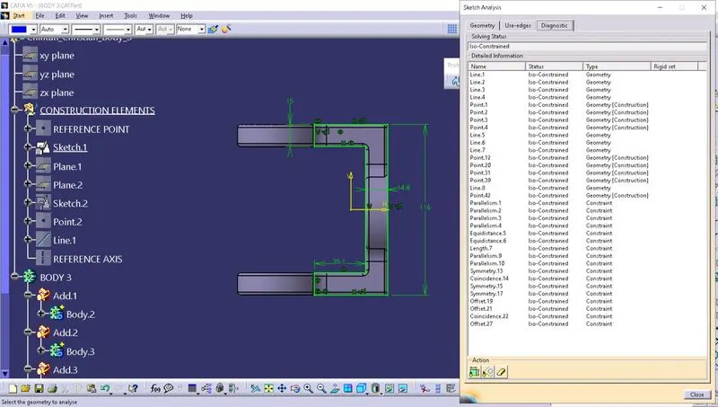
- Now, create sketch of circular base of 55 mm diameter and EXTRUDE Give it 2.5 mm SHELL THICKNESS.
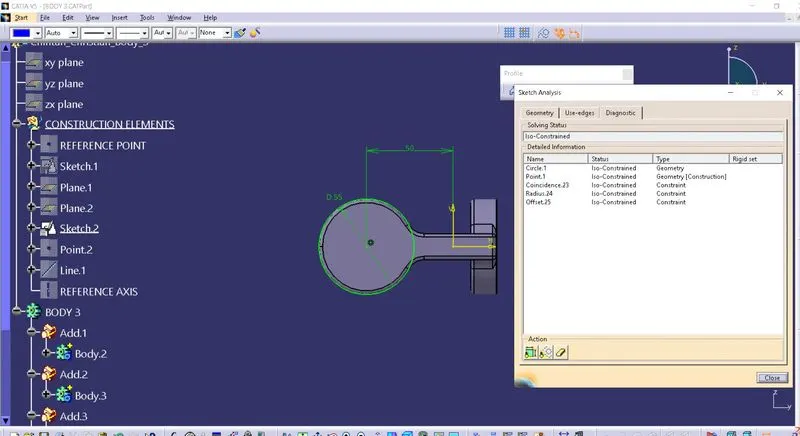
- MIRROR these circular base on other side as well as position it in middle of BASE using ROTATE option of 90° as shown in figure.
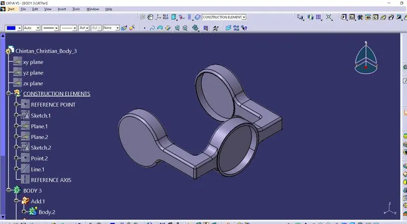
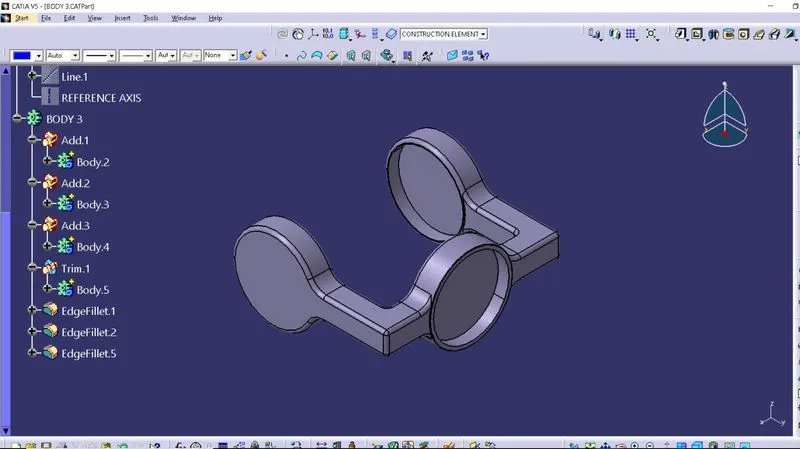
- Assemble these extrudes using ADD Boolean operation. Use UNION TRIM Boolean operation on rotated BASE. Apply fillet of 2 mm on edges.
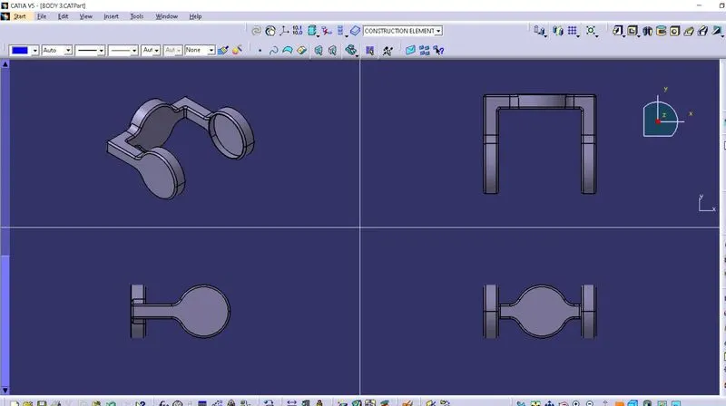
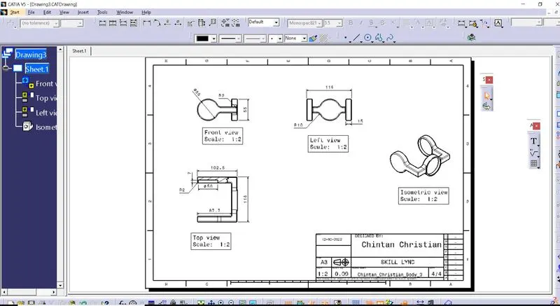
- Create drawing of the BODY 3 as per given file. Apply proper dimensions, style and add FRAME and TITLE BLOCK to it.
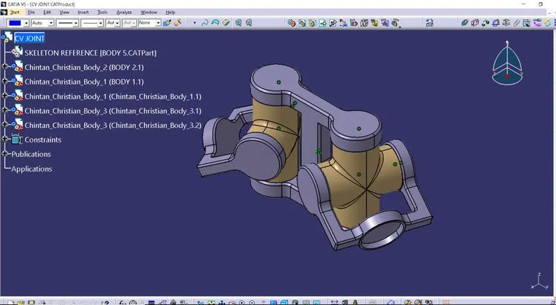
CREATING ASSEMBLY OF CV JOINT:
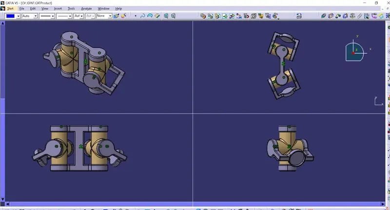
- First add new part in PRODUCT FILE of CV JOINT. Add Reference point & publish it with all 3 planes. Rename this part as “SKELETON REFERENCES”.
- Insert parts by using either COPY-PASTE or using NEW PART / EXISTING PART.
- Change relative positions of all parts using MANIPULATION
- Fix position of BODY 1 on SKELETON REFERENCE using COINCIDENT
- Add a reference point as well as reference axis to BODY 2. Coincide it with BODY 1 as shown in figure. Add another BODY 2.
- Insert two BODY 3 Add a reference point as well as reference axis to BODY 3. Coincide it with BODY 2 as shown in figure.
- Create BILL OF MATERIALS from ANALYZE Add required options to it.
- To generate BALLOONS in drawing, give numbers to assembly by using option ‘GENERATE NUMBERING’.
CREATING DRAWING OF ASSEMBLY OF CV JOINT:
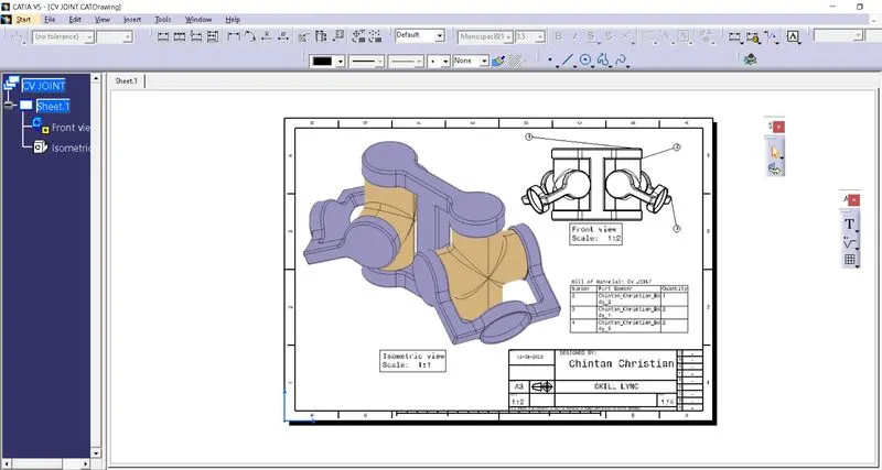
- Insert FRONT VIEW & ISOMETRIC VIEW of CV JOINT as required.
- To add colours and edges to ISOMETRIC VIEW, go to properties and use RASTER option and apply SHADES WITH NO EDGES.
- Apply proper dimensions, style and add FRAME and TITLE BLOCK to it.
- Insert BILL OF MATERIALS by selecting PRODUCT FILE OF CV JOINT.
- Generate Balloons from INSERT MENU for selected view.
QUICK RETURN MECHANISM
CREATING INDIVIDUAL PART BODIES:
BODY 1:-
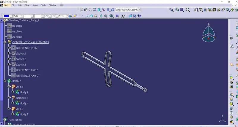
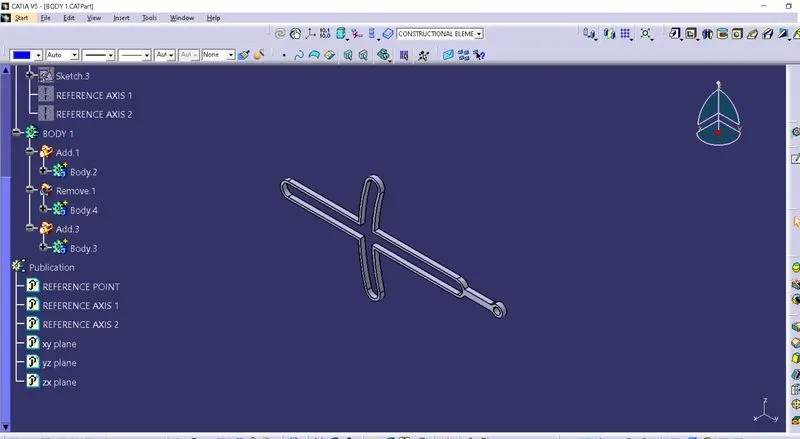
- First, create a sketch as shown in figure and EXTRUDE it about 4 mm.
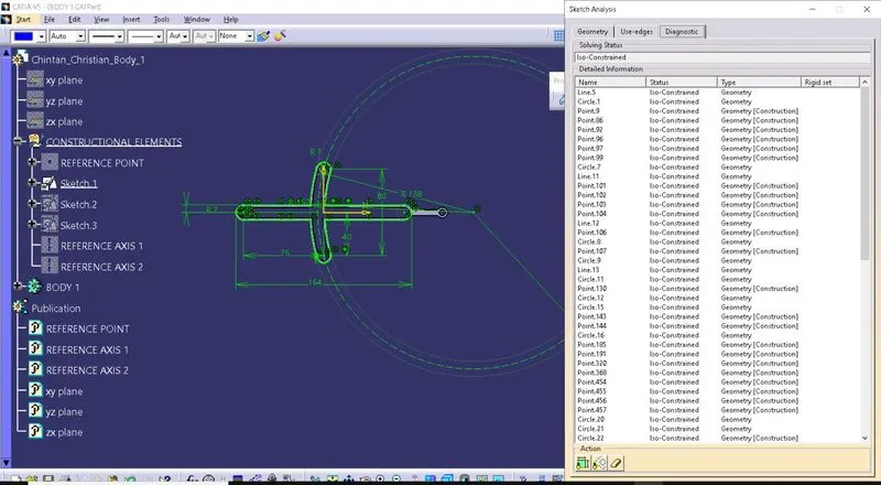
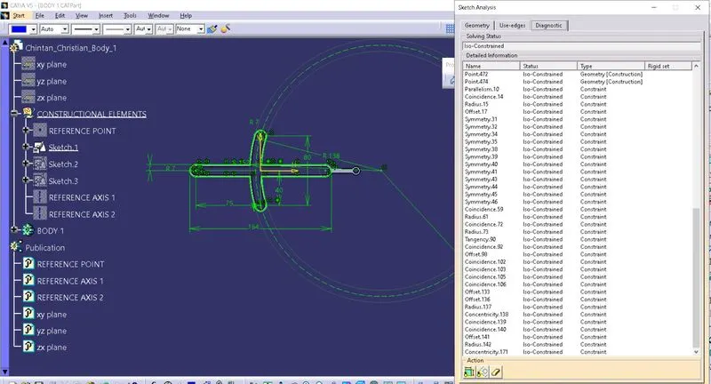
- Offset same sketch about 2 mm and EXTRUDE
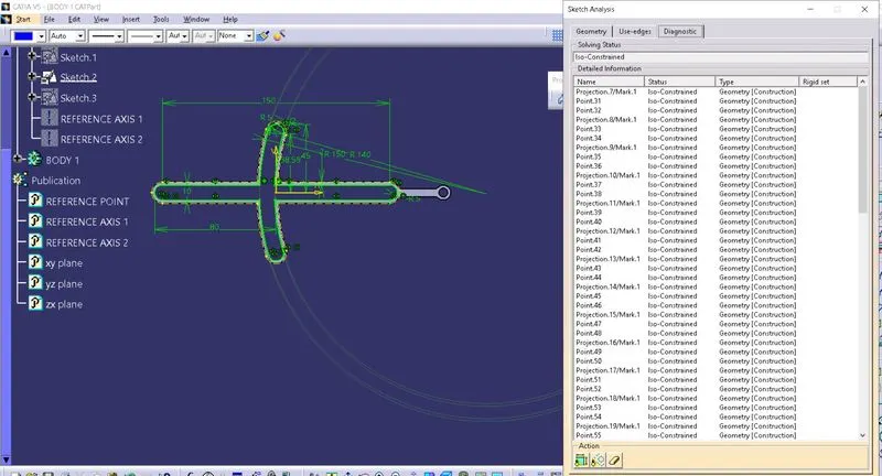
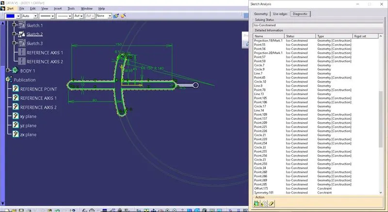
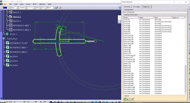
- Use ‘REMOVE’ Boolean operation to remove portion 2nd EXTRUDE from 1st EXTRUDE.
- Create sketch of tail portion and EXTRUDE
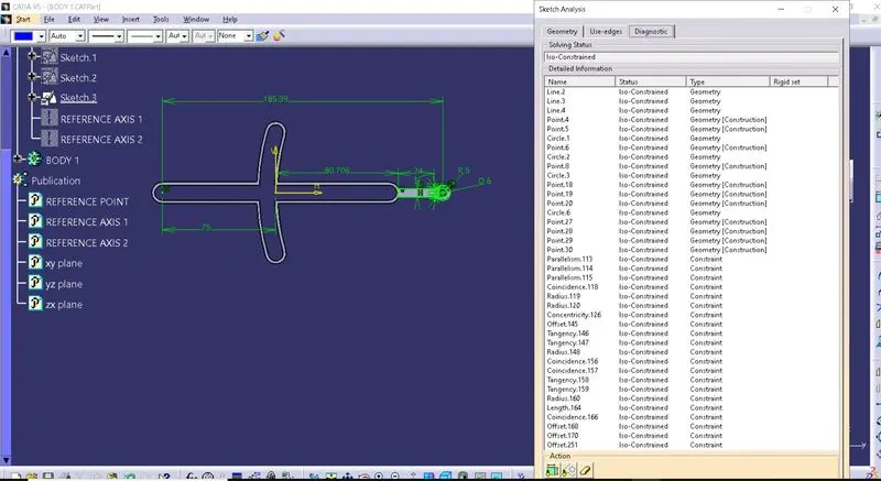
- Use ADD Boolean operation.
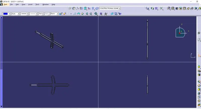
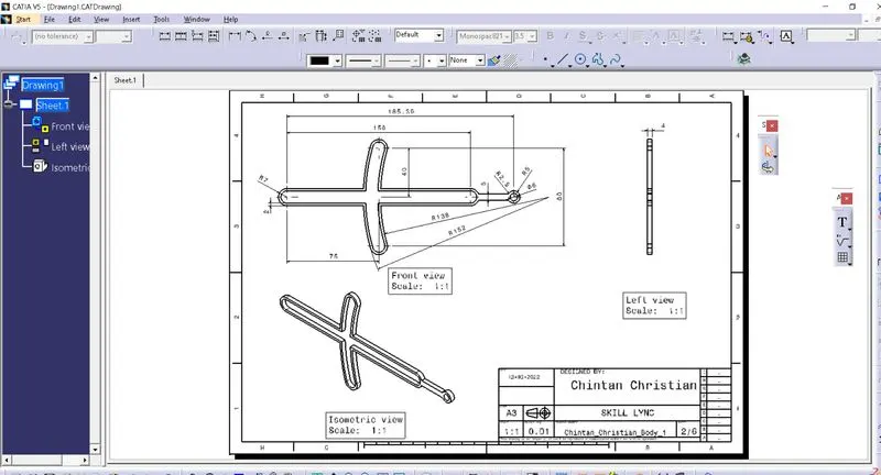
- Create drawing of the BODY 1 as per given file. Apply proper dimensions, style and add FRAME and TITLE BLOCK to it.
BODY 2:-
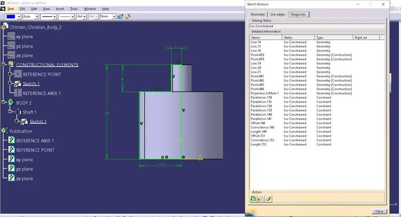
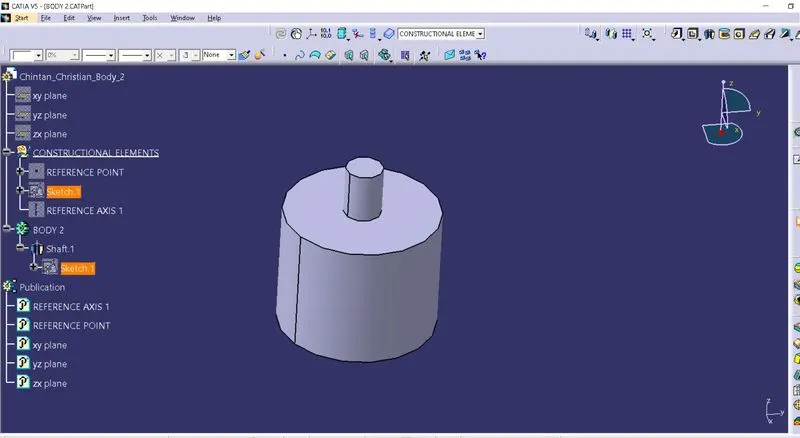
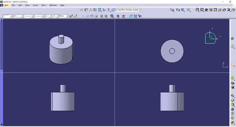
- First, create a sketch as shown in figure and REVOLVE it around center axis.
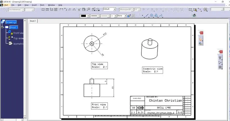
- Create drawing of the BODY 2 as per given file. Apply proper dimensions, style and add FRAME and TITLE BLOCK to it.
BODY 3:-
- First, create a sketch of rectangular boss as shown in figure. EXTRUDE it about 15 mm in both direction.

- Create a sketch of circular rod of 6 mm diameter as shown in figure and EXTRUDE
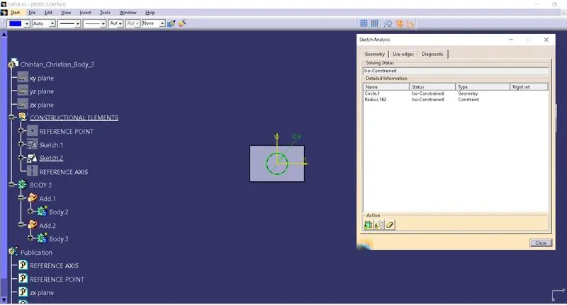
- Assemble these 2 extrudes using ADD Boolean operation.
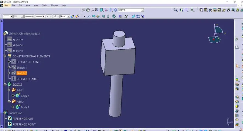
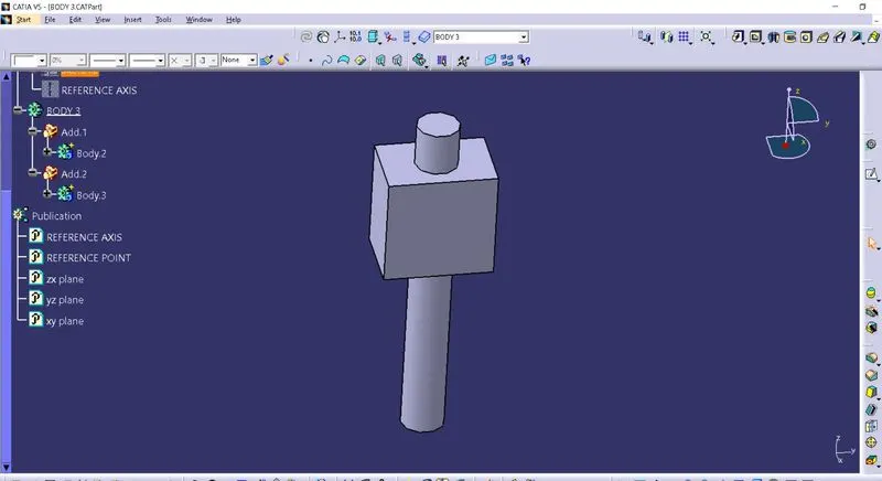
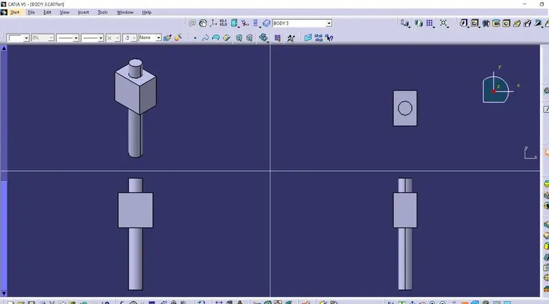
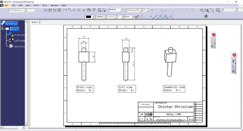
- Create drawing of the BODY 3 as per given file. Apply proper dimensions, style and add FRAME and TITLE BLOCK to it.
BODY 4:-
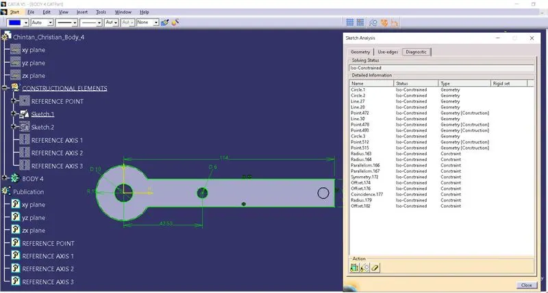
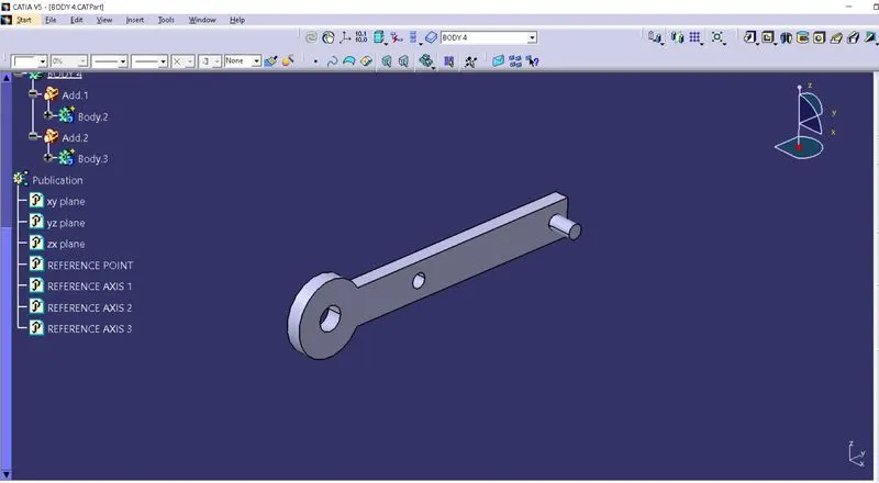
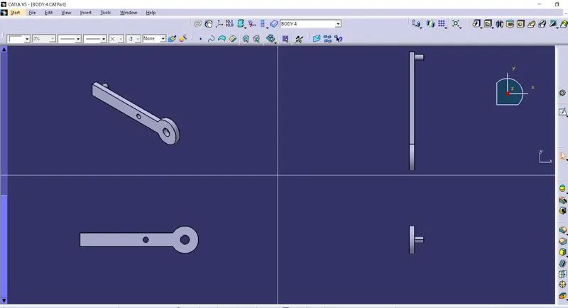
- First, create a sketch as shown in figure and EXTRUDE it about 6 mm.
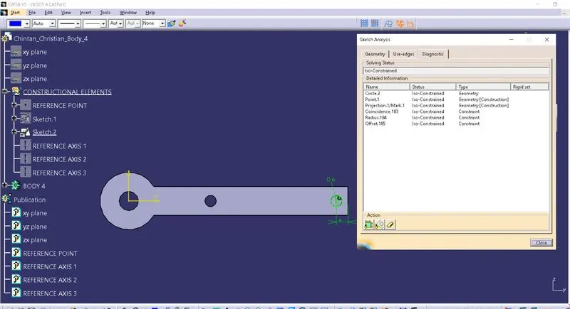
- Now create a sketch of a circular boss of 6 mm as shown in figure and extrude it about 16 mm length.
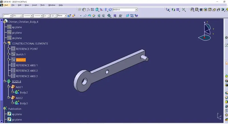
- Assemble these 2 extrudes using ADD Boolean operation.
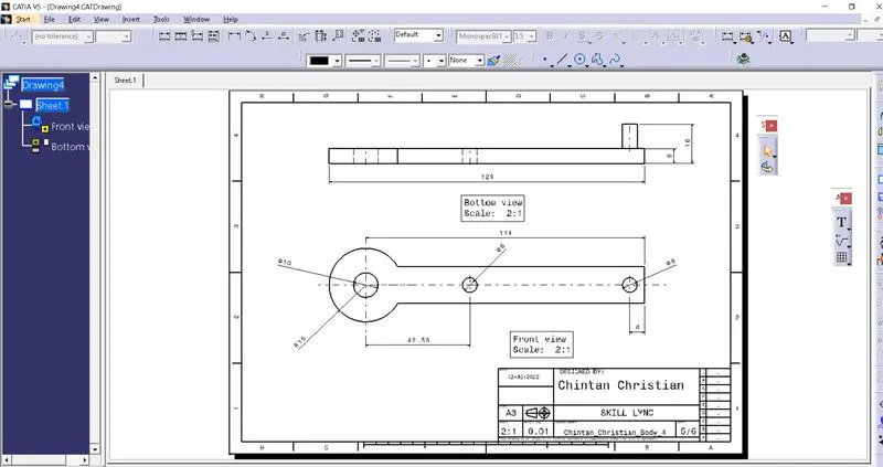
- Create drawing of the BODY 4 as per given file. Apply proper dimensions, style and add FRAME and TITLE BLOCK to it.
BODY 5:-
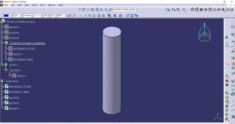
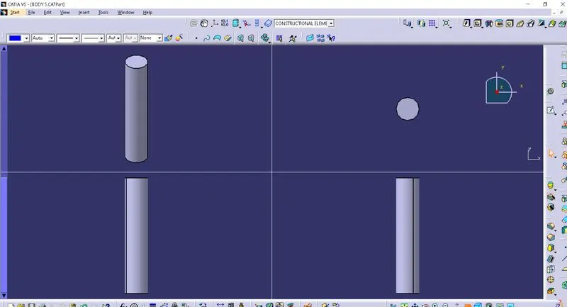
- First, create a sketch of rod of 10 mm diameter & 50 mm length as shown in figure and REVOLVE it around center axis.
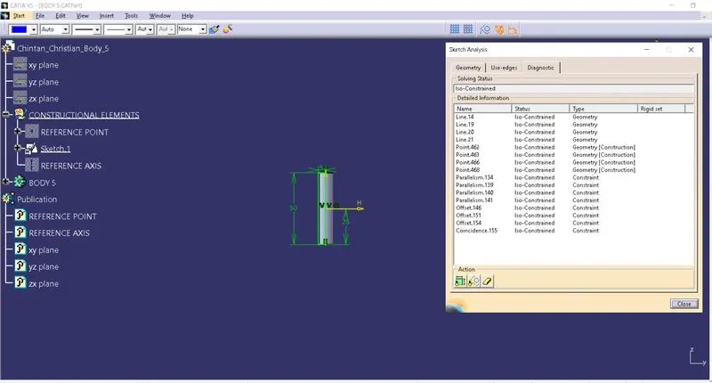
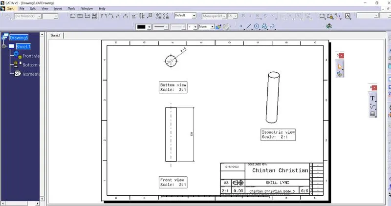
- Create drawing of the BODY 5 as per given file. Apply proper dimensions, style and add FRAME and TITLE BLOCK to it.
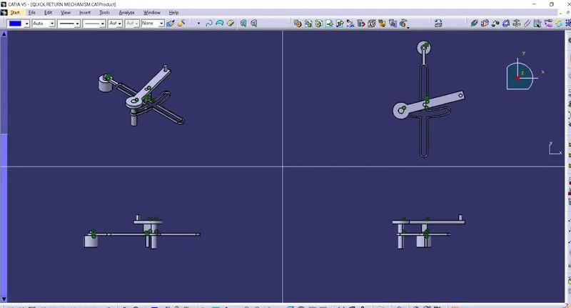
CREATING ASSEMBLY OF QUICK RETURN MECHANISM:
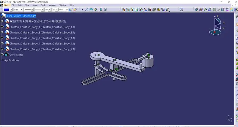
- First add new part in PRODUCT FILE of QUICK RETURN MECHANISM. Add Reference point & publish it with all 3 planes. Rename this part as “SKELETON REFERENCES”.
- Insert parts by using either COPY-PASTE or using NEW PART / EXISTING PART.
- Change relative positions of all parts using MANIPULATION
- Fix position of BODY 1 on SKELETON REFERENCE using COINCIDENT
- Add a reference point as well as reference axis to BODY 2. Coincide it with BODY 1 as shown in figure.
- Insert BODY 5 Add a reference point as well as reference axis to BODY 5. Coincide it with BODY 1 as shown in figure.
- Insert BODY 4 Add a reference point as well as reference axis to BODY 5. Coincide it & add contact surface with BODY 5 as shown in figure.
- Insert BODY 3 Add a reference point as well as reference axis to BODY 5. Coincide it with BODY 4 hole as shown in figure.
- Create BILL OF MATERIALS from ANALYZE Add required options to it.
- To generate BALLOONS in drawing, give numbers to assembly by using option ‘GENERATE NUMBERING’.
CREATING DRAWING OF ASSEMBLY OF QUICK RETURN MECHANISM:
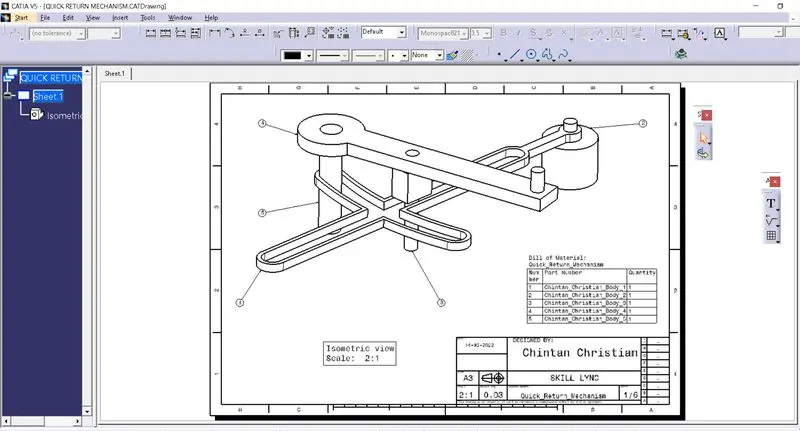
- Insert ISOMETRIC VIEW of QUICK RETURN MECHANISM as required.
- Apply proper dimensions, style and add FRAME and TITLE BLOCK to it.
- Insert BILL OF MATERIALS by selecting PRODUCT FILE OF QUICK RETURN MECHANISM.
- Generate Balloons from INSERT MENU for selected view.