Week 10- Assembly Workbench
Assembly Workbench.
Introduction:
In this challenge we create fully constrained assembly of a Cv Joint and a Quick return mchanism in Catia v5.
Cv Joint:
Parts:
The first step is to create the parts of the assembly. These parts are created in solid modelling workbench using various tools such as padding, fillets, chamfers etc. and Boolean operations such as assemble, add, remove etc.
Below are the various parts and the process of creating these components.
- Centre Support:
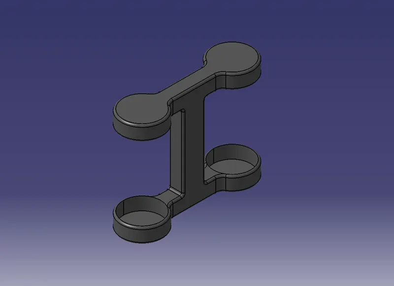
The part was created by first drawing its centre cross section in the front plane and using pad operation. The horizontal section containing the circular slots was created by padding the section with an offset value of the height of the centre pillar. This padded section was then mirrored along the horizontal plane to create the bottom section. The slots were created by using the remove Boolean operation.
- Cylindrical Blocks:
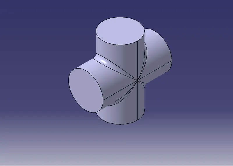
The part has a simple contour; hence it was created by creating two cylinders using pad tool and then using assemble Boolean on the two bodies. The edges were filleted for the given value using the edge fillet tool.
- Side Clamps:
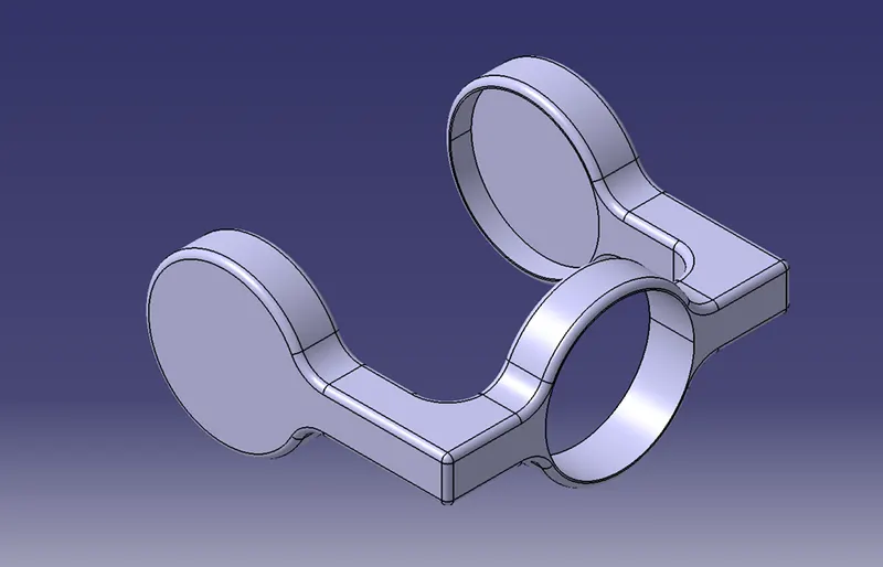
The component had a cylindrical hole at eh centre, so first we created the centre region by padding its respected sketch. The side sections were mirrored along the centre plane by first creating its sketch and padding it for given dimensions. The slots were removed using the remove Boolean on a cylindrical padding of the given length.
Assembly:
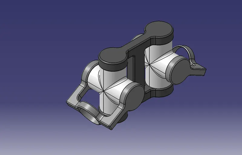
The components were assembled and constrained by applying suitable constraints. The parts are all assembled on a reference origin created inside the assembly itself. The parts are functional and can rotate in the assembly as intended.
Quick Return Mechanism:
Parts:
- Main Body:
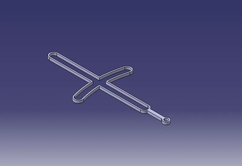
The main body consists of two slots and a pin hole for fixing it. The complete contour is created by sketching it in the horizontal plane and padding it to a thickness of given value. The slot is created by sketching the same section and offsetting it by given value and then creating a padded body. This body can then be removed from the main body by using remove Boolean operation.
- Rotating Handle:
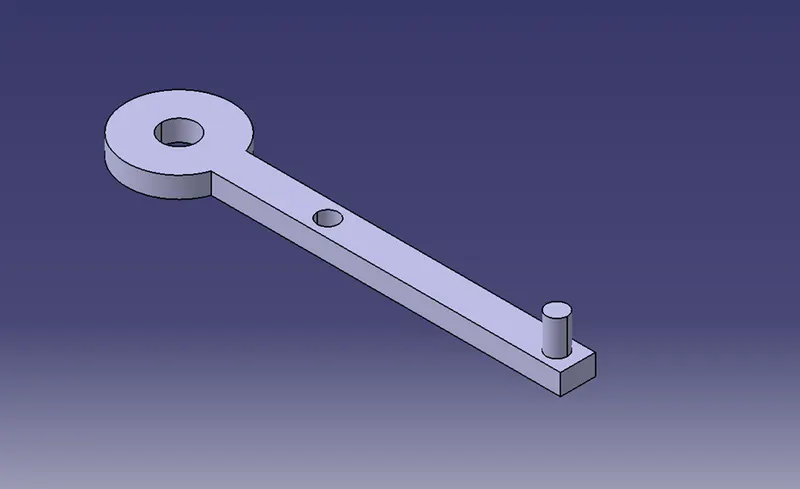
This part is created in a similar way to the main body by padding its sketch along with the holes. The pin is created separately and then added by using the assemble Boolean on the main handle body.
- Centre Slider Pin:
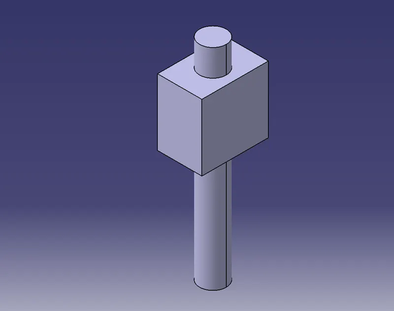
This part is created by simply padding the two sections up to their given dimension values and then adding them together.
- Side Slider Pin:
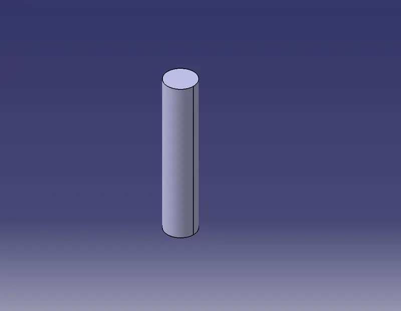
This part only consists of a single padded cylinder created by padding a circular sketch for its given length.
- Base Block:
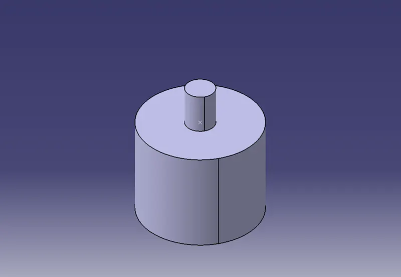
The base block has two different cylindrical sections that are added together using Boolean operations.
Assembly:
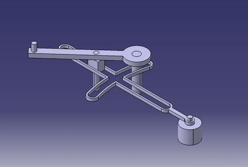
The components were assembled and constrained by applying suitable constraints. The parts are all assembled on a reference origin created inside the assembly itself. The parts are functional and can rotate in the assembly as intended.