Week 1 Stress Concentration on a Plate with hole
Aim: To perform static structural analysis to determine the stress concentration on a plate with holes.
Objective:
- Design a plate with a hole. (Case 1)
- Design a plate with three holes of different diameters. (Case 2)
- Determining the maximum deformation and stress developed in both models.
- Comparing the result of two cases and declining which cases to select from analysis and manufacturing point of view.
Introduction:
The stress at the edge of a hole, or at a notch root, has a higher value than the remote stress. This phenomenon is called stress concentration.
- In the presence of ductile yielding, stress concentrations are relatively unimportant since the yielding which will occur at the concentration, e.g. the tip of a notch, will merely redistribute the stresses and not necessarily lead to failure. If, however, there is only marginal ductility, or in the presence of low temperatures, then stress concentrations become more significant as the likelihood of brittle failure increases. it is wise, therefore, to keep the stress concentration factor as low as possible.
- For brittle materials like cast iron, internal stress concentrations arise within the material due to the presence of e.g., flaws, impurities or graphite flakes. These produce stress increases at least as large as those given by surface stress concentrations which, therefore, may have little or no effect on failure. A cast iron bar with a small transverse hole, for example, may not fracture at the hole when a tensile load is applied.
Given:
Case :1
Plate dimensions:
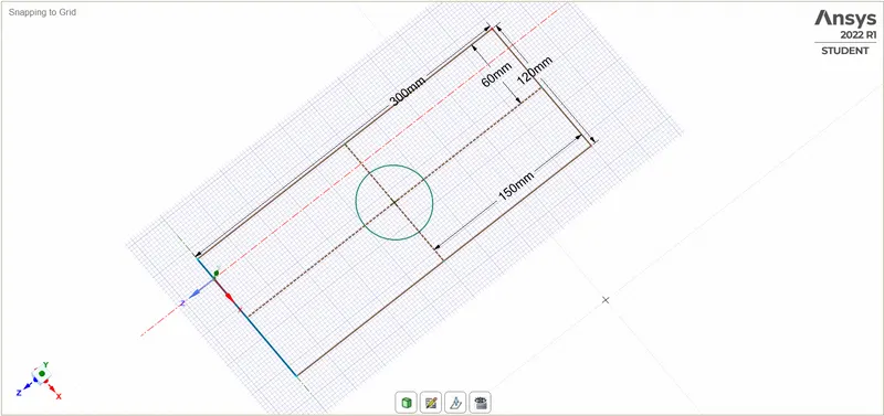
Length=300mm
Height=120mm
Thickness=30mm
Circular Hole at the centre:
Diameter=60mm
Case 2:
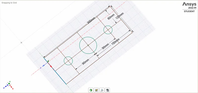
Smaller holes 90mm away from the centre:
Diameter=30mm
Boundary Conditions:
Plate fixed at left face.
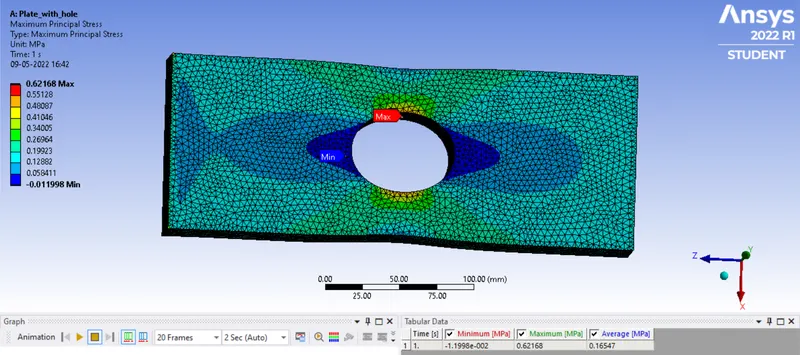
Load of 500N on the right face.
Steps have to be taken during the analysis:
- Open the Ansys Workbench.
- Select the proper engineering data (material).
- Create a geometry.
- Mesh the geometry.
- Give the boundary conditions.
- Apply the solver to solve.
- Results analysis.
Procedure:
- First, we need to open the workbench from the computer.
- Select the static structural module.
- Now from the tab select the engineering data for material selection.
- Create a geometry as per the given dimension from the next geometry module.
- After creating the geometry come on the same tab and go to the Model module and update the model.
- After updating the model choose the Edit option in the model tab.
- it will open the mechanical tab, where we going to perform the analysis.
- In this module, we have to mesh the model as per requirement.
- Then after meshing give the material as per requirement.
- Now come with the boundary condition, here we gave fixed and forced to opposite faces for tensile test.
- After giving the boundary condition we need to assign an output request so that we can see what we want from the results.
For both cases, we use the static structural tools in the analysis system toolbox to define the geometry and other input parameters for the same.
In the engineering data, we input the material and its properties. (e.g. structural steel)
T design the model with given dimensions, SpaceClaim is used in the geometry tab. Case 1 and case 2 are given below pictures.
Defining the given dimensions for the geometry for Case 1:
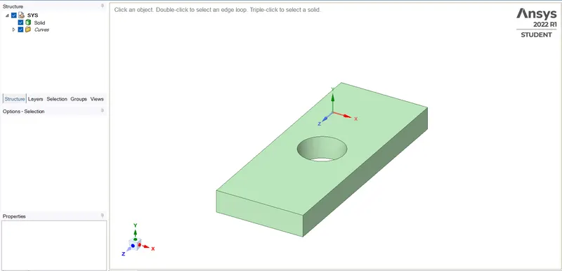
Extruding the geometry to three-dimensional geometry.
The resulting geometry is given below:
Defining the given dimensions for the geometry for Case 2:
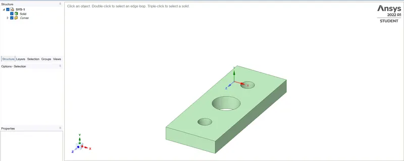
Extruding the geometry to three-dimensional geometry.
The resulting geometry is given below:
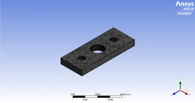
By opening the modelling tab, we mesh the geometry with an element size of 2mm and the method of solving used is the tetrahedron element type. Generating the mesh thereafter by right-clicking on the Mesh icon.
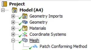
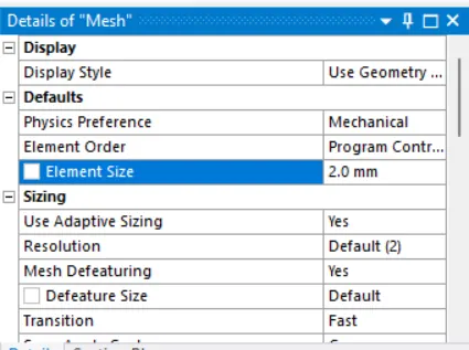
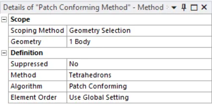
Meshing geometry for Case 1:
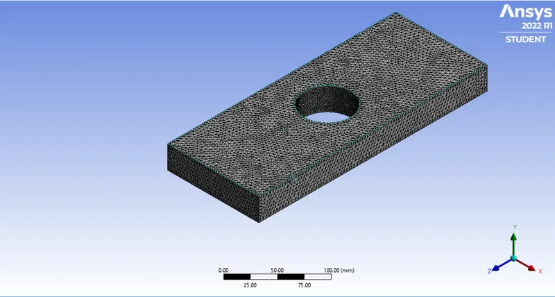
Meshing geometry for Case 2:
Now, to define the boundary conditions, we specify the faces for the fixed support and load.
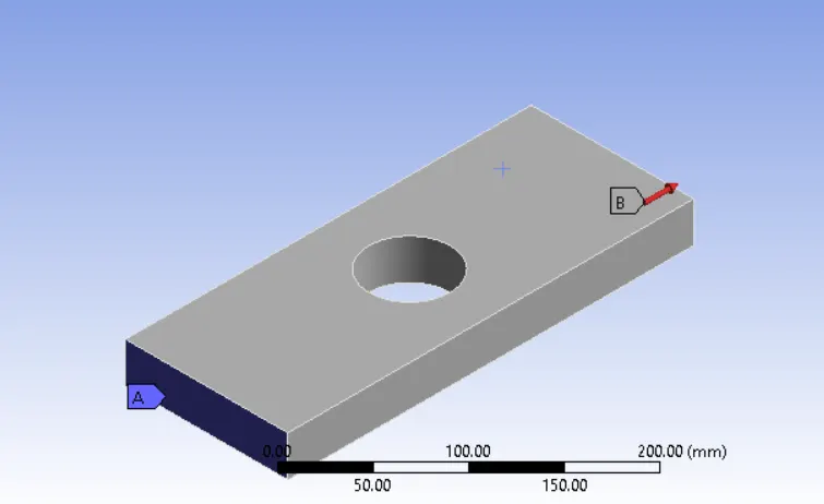
Defining fixed support for Case 1 on the left side
Defining fixed support for Case 2 on the left side
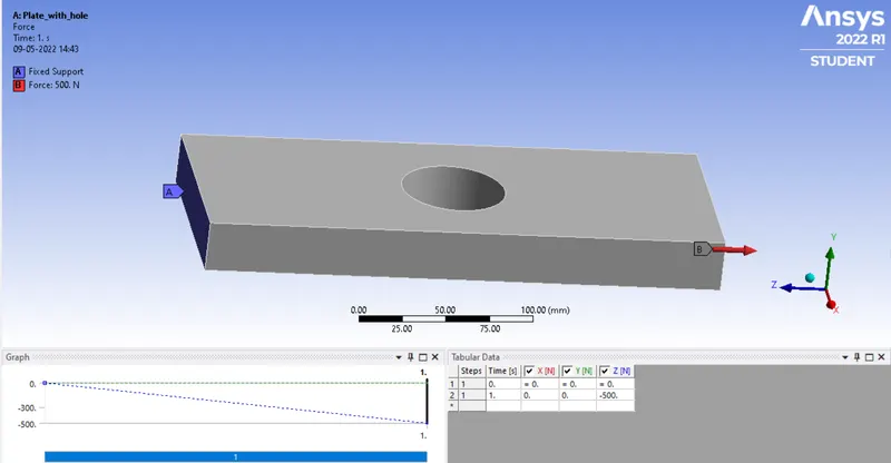
Defining force load for Case 1 on the right side in the positive 'z' direction
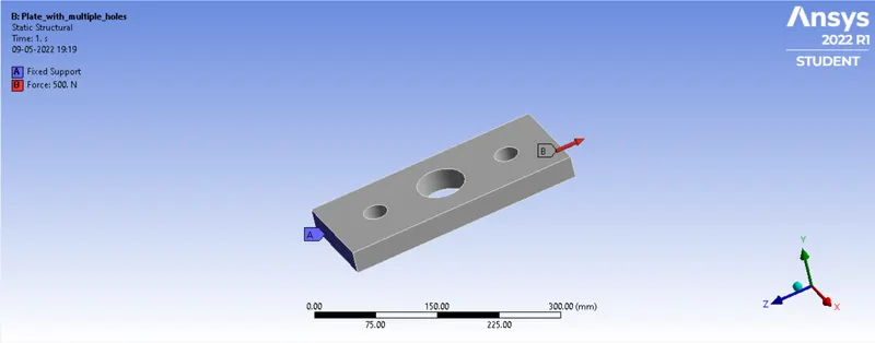
Defining force load for Case 2 on the right side in the positive 'z' direction
Selecting the type of solution and solving it for Total deformation and Equivalent stress for results.
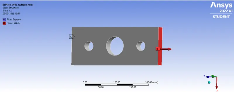
Total deformation for Case 1:
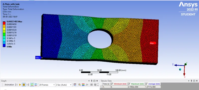
Total deformation for Case 2:
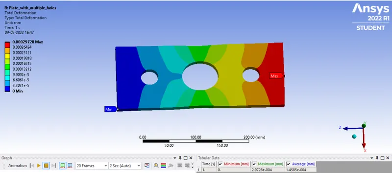
Equivalent Stress for Case 1:
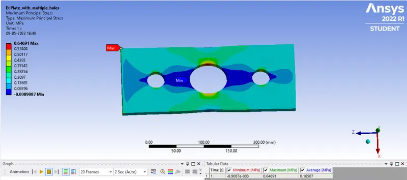
Equivalent Stress for Case 2:
Results:
| Sr.No | Solution | Plate with a hole (Case 1) | Plate with three hole (Case 2) |
| 1. | Total Deformation (Maximum) in mm | 2.7492e-004 | 2.9728e-004 |
| 2. | Total Deformation (Mimimum) in mm | 0 | 0 |
| 3. | Equivalent Stress (Maximum) in MPa | 0.62168 | 0.64691 |
| 4. | Equivalent Stress (Minimum) in MPa | -1.1998e-002 | -8.9087e-003 |
Conclusion:
- From the results above, we can conclude that the plate with a hole has less deformation than the plate with three hole.
- Stress level in plate with hole has higher than the plate with three holes.
- From analysis point of view, we can say that choosing plate with one hole because if we compare the stresses for both cases its minimal level. e can also choose plate with three holes, which is computationally inexpensive at the cost of result which we produced.
- From manufacturing point of view, we can choose plate with one hole because it has less number of holes which in turn causes less work for application, thus resulting in saving total production cost.
Note: google drive link is provided below in txt file. Plese check toward the link for model.
Thank You...