Week 1 Stress Concentration on a Plate with hole
OBJECTIVE :- Design and Perform a Tension test on a plate in two different cases and compare the results
Case :1
Design a plate with a hole model.
Determine the maximum deformation and stress developed in the model.
Plate dimensions:
Length=300mm
Height=120mm
Thickness=30mm
Circular Hole at the center:
Diameter=60mm
Case 2:
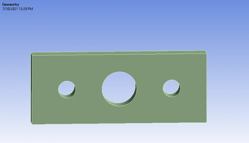
smaller holes 90mm away from the center:
Diameter=30mm
Boundary Conditions:
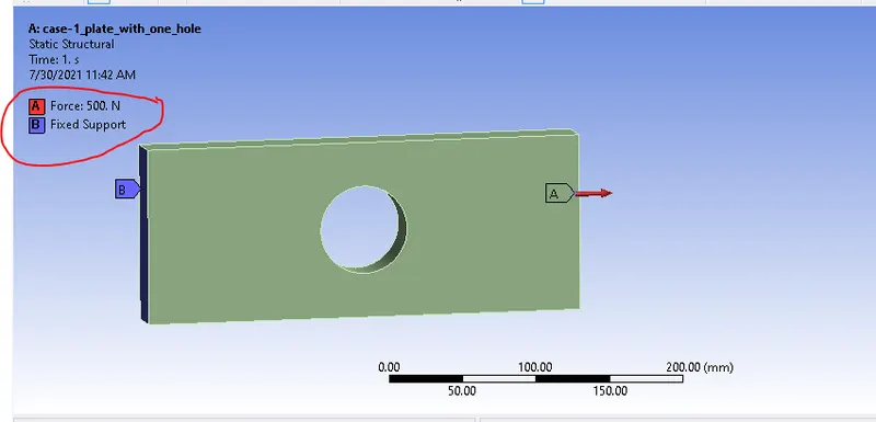
Plate fixed at left face.
Load of 500N on the right face.
Consider you are a Product Engineer in an Automotive industry.
You are assigned the following responsibilities:
- Compare the deformation and maximum stress developed on a structural steel model for the 2 cases
- From an analysis standpoint, which of the design will you select? Explain why?
- From a manufacturing standpoint, which of the design will you select? Explain why?
- Write a Detail Report.
CASE SETUP
case1
- Static structural selected from analysis system
- Engineering data - it can be addited to add or remove materials from the library, structural steel selected from library for this projct.
- Geometry - we can directly create geometry from space claim or we can import the cad model, but in this project we created 3D cad model in space claim.
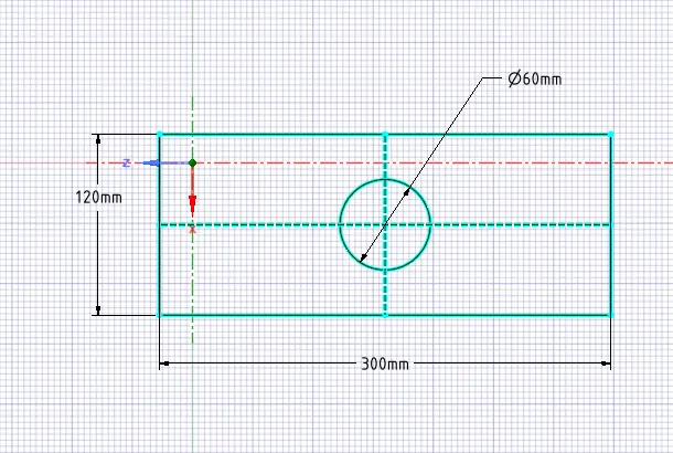
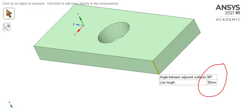
- open mechanical module by double clicking model option in project schematic
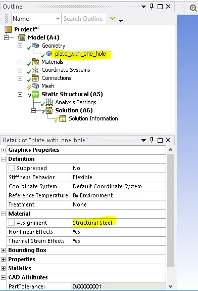
- Rename the model and assign structural steel to the model.
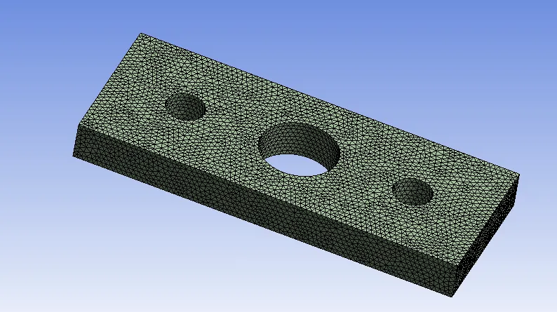
- Create a tetra mesh with an element size of 4mm
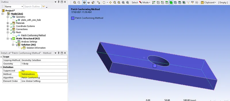
- Create a boundary conditions as per the given question
- Request for von-mises enginering stress, von-mises enginering strain and total deformation.These are the typical output requests.
- To get the solution go to solution-right click- solve.
case2
- case setup is same for both (case1&2) cases but geometry is different, in this we created a plate with 3 holes as per given dimensions.
RESULTS :-
| Type | case 1 | case2 |
| von-mises enginering stress | 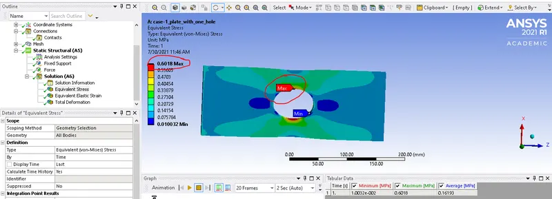 |
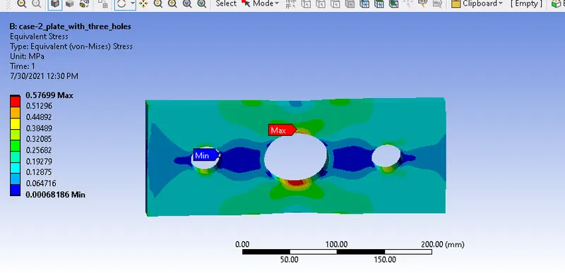 |
| von-mises enginering strain | 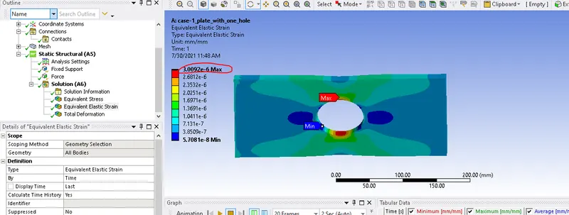 |
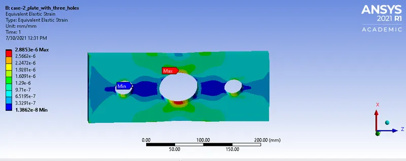 |
| total deformation | 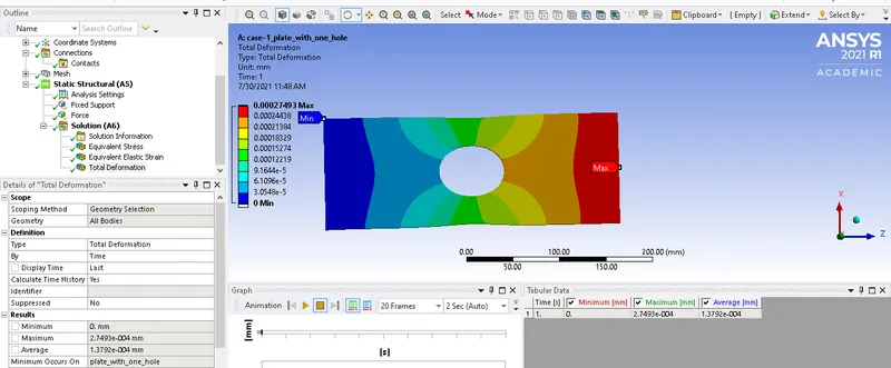 |
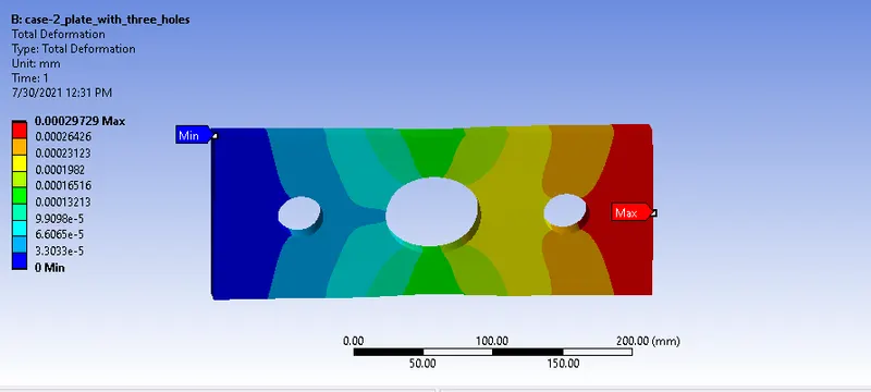 |
CONCLUSION
- Stress is lower in case 2 ( 0.57699mpa) compare to case1 ( 0.6018), due to the flow of stress lines being smoother than case1.
- Deformation is higher in cas 2 (0.00029729) compare to case 1( 0.00027493) due to the additional hole.
- In Analysis point of view case2 design is safer due to low stress but defrmation is littile higher but it is negligible.
- In Manufacturing point of view case1 design is good, because case2 design requires two additional holes to be drilled only to obtain small decrease in stress levels.
RECOMMENDATION
I recommnded case1 model over case2, because case2 model needs more manufacturing cost and time. Assembly cost of case2 is more because it requires more fixtures.