Week 1 Stress Concentration on a Plate with hole
STATIC STRUCTUAL ANALYSIS ON A PLATE WITH HOLE
OBJECTIVE
To perform Static Structural analysis on a Plate with hole and determine the maximum deformation and stress developed in the model
Two different cases are to be used, they are as follows:
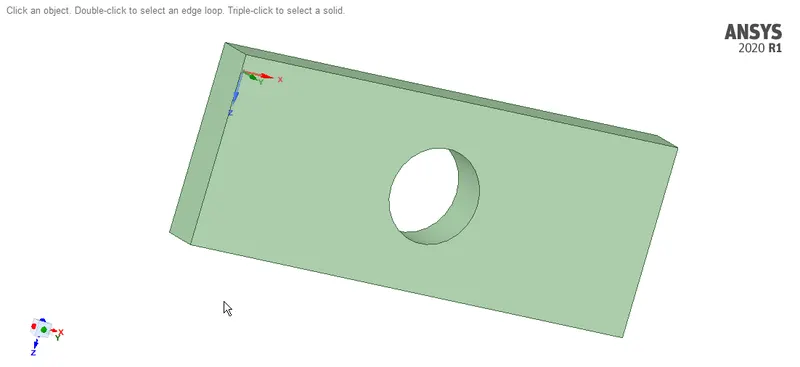
Case 1: A Plate with dimensions (300*120*30) mm with Circular hole of 60 mm diameter at the centre
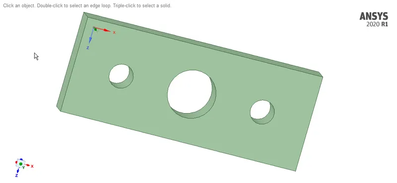
Case 2: A Plate with dimensions (300*120*30) mm with Circular hole of 60 mm diameter at the centre and smaller holes of 30 mm diameter, 90mm away from the centre
In these two cases,
- Fixed Support must be applied on the left face
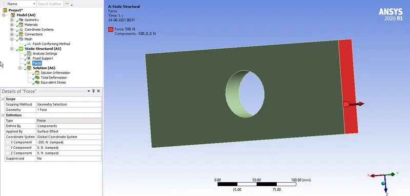
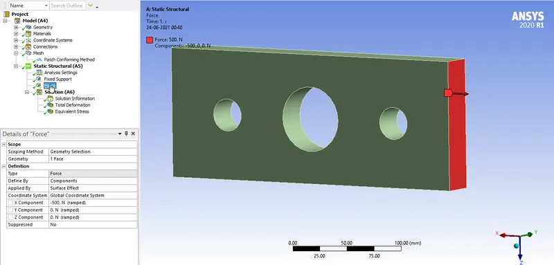
- Force of 500 N must be applied on the right face
The Deformation and the Maximum Stress developed are to be compared and Proper design must be selected based on Analysis point of view and Manufacturing point of view and appropriate reasons have to be provided
MODEL SETUP
The 3D model of the setup is imported into ANSYS Space Claim. Check for any abnormalities in the Geometry.
The Geometry used for two different cases are shown below
Case 1:
Case 2:
MATERIAL ASSINGMENT:
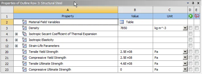
Structural Steel is assigned to the Plate. The material properties are shown below
- Structural Steel:
MESHING:
The meshing is done as follows,
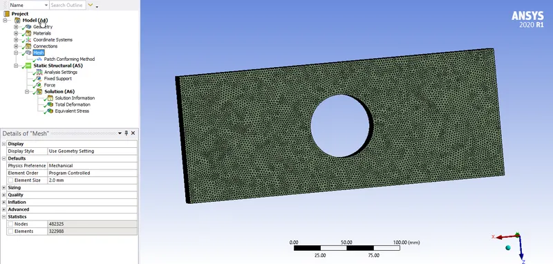
- The Plate with hole is meshed with Tetrahedron elements with Patch Confirming Algorithm:
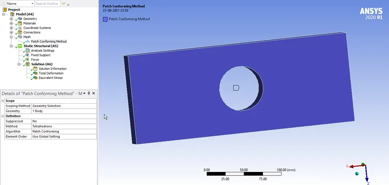
- A mesh of element size 2 mm is assigned for the model:
MESH QUALITY:
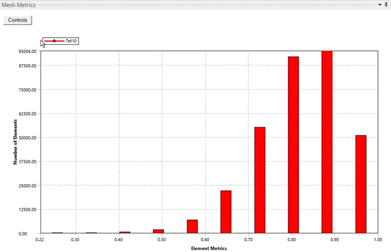
The above meshing is also done for the Case 2.
BOUNDARY CONDITIONS:
The boundary condition for this model are
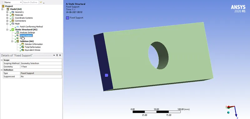
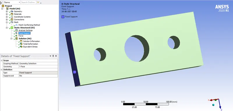
- A Fixed Support on the left face of the Plate:
Case 1:
Case 2:
- A Force of 500 N on the right face of the Plate
Case 1:
Case 2:
ANALYSIS SETTINGS:
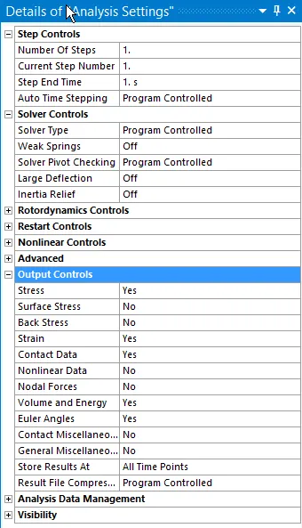
Now, the simulation is run for 1 step. Auto Time stepping is Program Controlled, which is a default setting. Other controls are of default setup and are shown below
RESULTS:
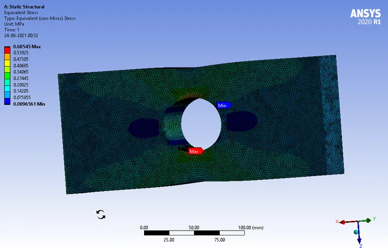
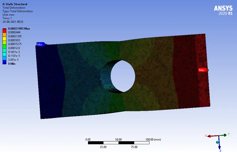
CASE 1: A Plate with dimensions (300*120*30) mm with Circular hole of 60 mm diameter at the centre
Total Deformation:
- Equivalent Stress:
- Total Deformation:
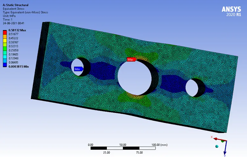
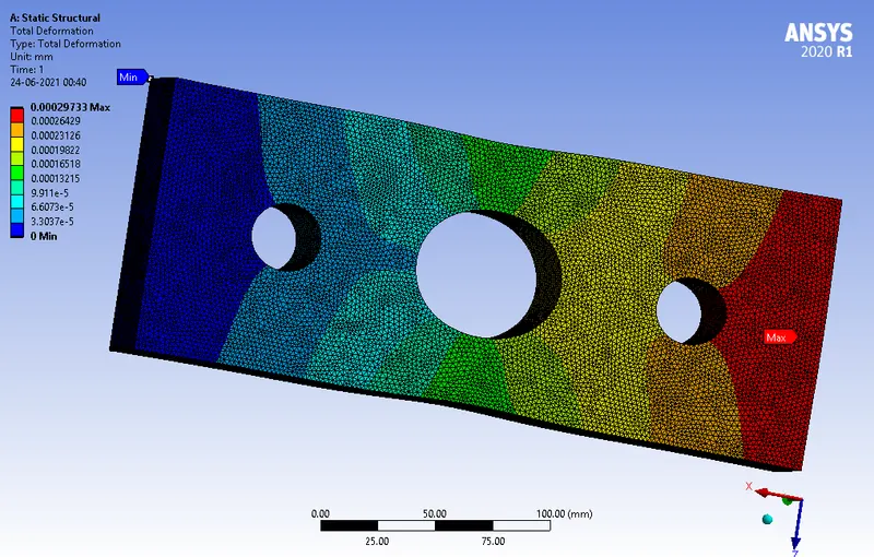
Case 2: A Plate with dimensions (300*120*30) mm with Circular hole of 60 mm diameter at the centre and smaller holes of 30 mm diameter, 90mm away from the centre
- Equivalent Stress:
- Total Deformation:
CONCLUSION:
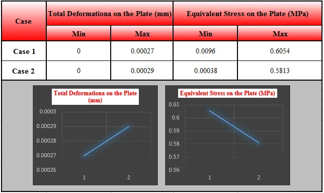
From the results, it can be inferred that,
1. Equivalent stress and Deformation are almost same for the two cases but,
- Equivalent stress decreased when two additional holes are made in the Plate because stress is evenly distributed throughout the plate when compared to the case 1, with one hole in the Plate, where there is abrupt change in the dimension of the components and so stress developed is high
- Total Deformation in the Case 2 is high compared to that of Case 1 because, as additional holes are created in the Plate, the Stiffness behaviour of the component decreased
2. From the analysis point of view, we can select the Plate with three hole as in Case 2, because the Stress developed in the plate is less compared to Case 1 which leads to increased life of the component and the computational cost of analyzing is reduced, as the area /body to be meshed is less.
3. From the manufacturing point of view, Plate with one hole can be selected because stress developed and deformation is almost equal to that of Case 2, and the cost involved to manufacture Plate with three holes is high compared to Case 1. Further, the material wastage and time required to manufacture the component is also less in Case 1. Hence Plate with one hole can be selected.