Week 1 Spur Gear Challenge
WEEK 1 : SPUR GEAR CHALLENGE
1. Objective
To find out Equivalent Stress, Total Deformation and Stress Intensity of the given Spur Gear model with three different material assignment - Cast Iron, Cast Steel and Cast Bronze and identify the possible location of fracture.
2. Simulation Setup
The file "Spur_Gear.stp" is imported first and then material is assigned to it. The cast iron material is available in Granta Design sample materials in ANSYS student edition while material is defined manually for Cast Steel and Cast Bronze using the data provided in the problem. After material assignment, target and contact faces of both the gear teeth are defined using "Face" selection option. The following options are given as a user input for the setup -
2.a Contact Region
Contact Type - Frictional
Behaviour - Symmetric
Formulation - Augmented Lagrangian ( to avoid penetration and chattering of teeths during sliding)
Interface Treatment - Adjust to Touch
2.b Contact Joints
Connection Type - Body to Ground
Type - Revolute Joint
2.c Analysis Settings
No of Steps - 6
Large Deflection - ON
Auto time stepping - ON
Define By - Time
Carry over time step - OFF
Initial Time Step - 0.2
Min Time Step - 5e-2
Max Time Step - 0.5
2.d Boundary Condition
Type - Rotation (for left gear) , Moment ( for right gear).
The value of moment assigned is -10 Nm. The rotation angle in 6 steps is assigned as 0,30,60,90,120,150,180.
3. Meshing
A default mesh size of 3 mm is considered for all the three cases. Both tetrahedral and hexahedral elements are used for meshing. Due to Ansys Academic Version size limit restrictions mesh size could not be reduced further.
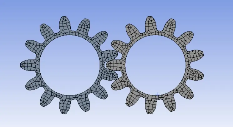
Fig 1. Meshing of the two gears
4. a. Simulation Results for Cast Iron
The simulation results when Cast Iron is defined as material for the two gears are shown below.
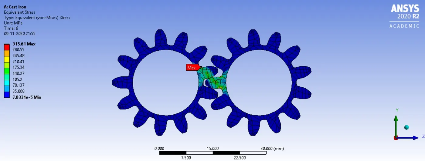
Fig 2. Equivalent Stress - Cast Iron
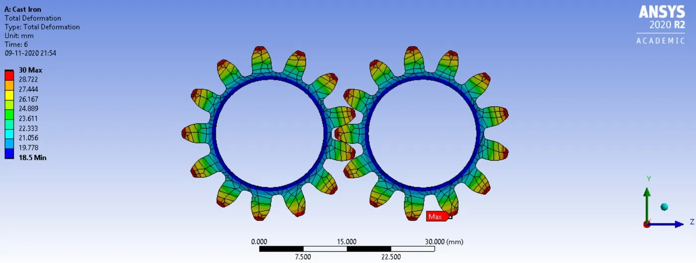
Fig 3. Total Deformation - Cast Iron
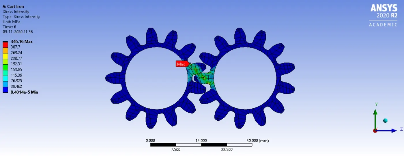
Fig 4. Stress Intensity - Cast Iron
4. b. Simulation Results for Cast Steel
The simulation results when Cast Steel is defined as material for the two gears are shown below.
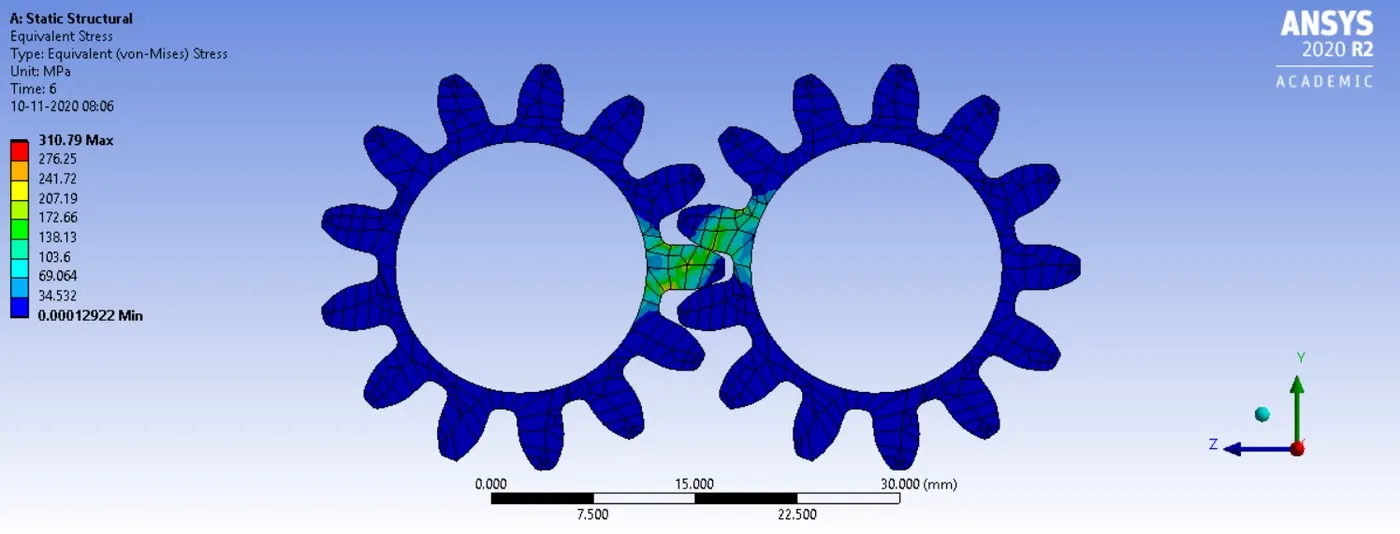
Fig 5. Equivalent Stress - Cast Steel
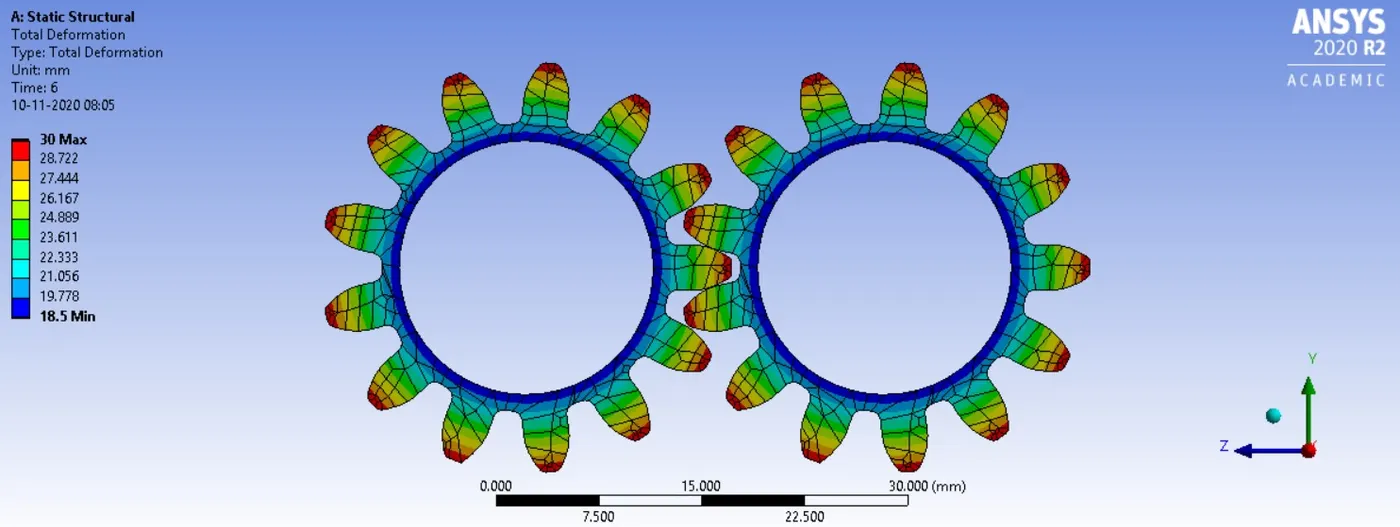
Fig 6. Total Deformation - Cast Steel
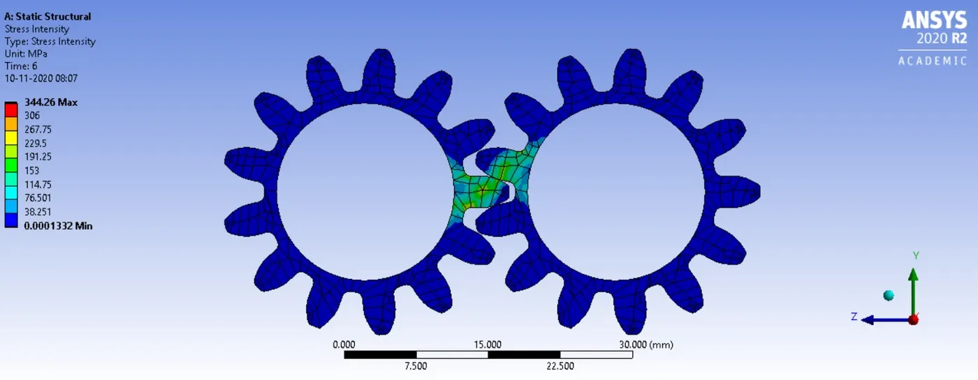
Fig 7. Stress Intensity - Cast Steel
4. c. Simulation Results for Cast Bronze
The simulation results when Cast Bronze is defined as material for the two gears are shown below.
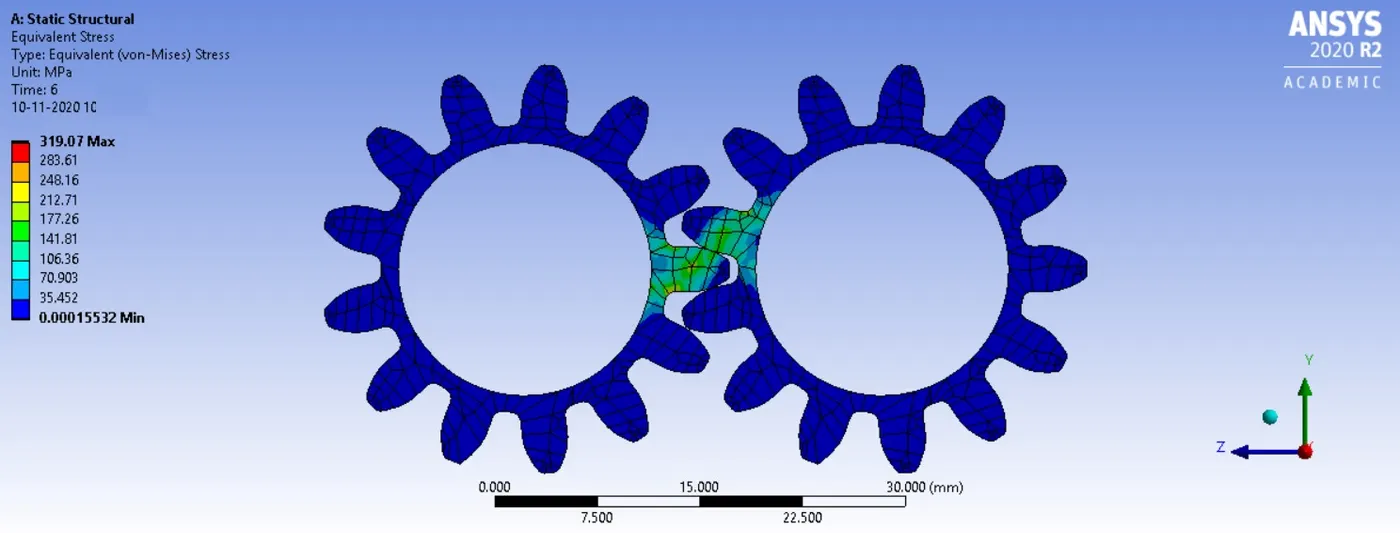
Fig 8. Equivalent Stress - Cast Bronze
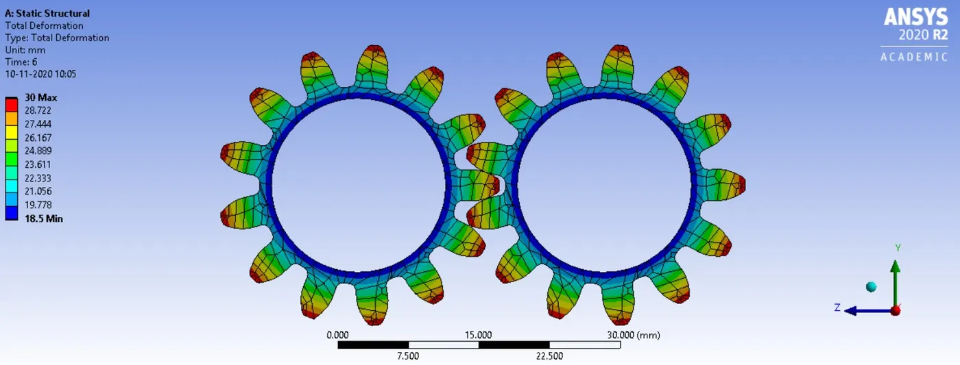
Fig 9. Total Deformation - Cast Bronze
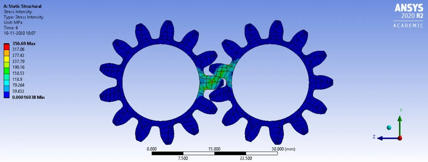
Fig 10. Stress Intensity - Cast Bronze
5. Result Comparison
The comparison of solution obtained after the simulation for three different material assignment are given in the table below.
Table 1. Comparison of Results
| SL No | Parameters | Material | ||
| Cast Iron | Cast Steel | Cast Bronze | ||
| 1 | Equivalent Stress | 315.61 Mpa | 310.79 Mpa | 319.07 Mpa |
| 2 | Total Deformation | 30 mm | 30 mm | 30 mm |
| 3 | Stress Intensity | 346.16 Mpa | 344.26 Mpa | 356.69 Mpa |
From the above results it can be seen that both the equilavant stress and stress intensity is highest in case of Cast Bronze and lowest in case of Cast Steel. Cast Steel is more ductile due less percentage of carbon as compared to Cast Iron and thus the stress value is less. So from the analysis point of view it will be safer to use Cast Steel as a material for the above problem.
6. Location of Failure
The material will fail once the stress intensity exceeds its fracture toughness and at this point crack will grow in rapid and unstable manner before fracture. The region where stress intensity value is recorded highest is shown below using a probe.
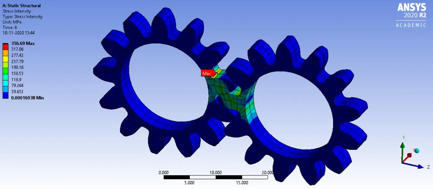
Fig 10. Location of Failure