Week 1 Spur Gear Challenge
Objective:
To carry out the static structural analysis on the spur gear using different kinds of materials and set boundary conditions are constant for all cases.
Case:1
Using Cast Iron(ductile) as a material, carry out a static structural analysis to find out Equivalent stress, Total deformation, and Stress intensity(Learn about what stress intensity is). Find a location for a possible fracture.
Case:2
Using Cast Bronzeas material, perform the same analysis for the results as in Case 1.
Case:3
Using Cast Steel as material, perform the same analysis for the results as in Case 1.
Procedure:
For all cases, procedures are the same but the material assignment will be changed.
Model:
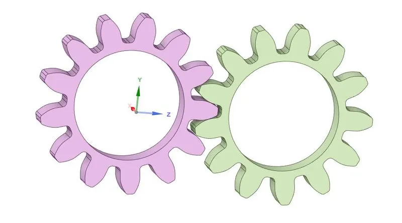
Open ansys>static structural>geometry>import. Now the model will be shown in the space claim window.
Go to material>edit>engineering sources. Now define the material or add new material.
At first, define the three materials from the engineering sources tab. If it is not there, We need to create a new material card in the material definition tab.
Go to model>edit. Now assign material for the model one by one.
Here we should perform three different materials such as cast iron(case-1), cast steel(case-2), cast bronze(case-3).
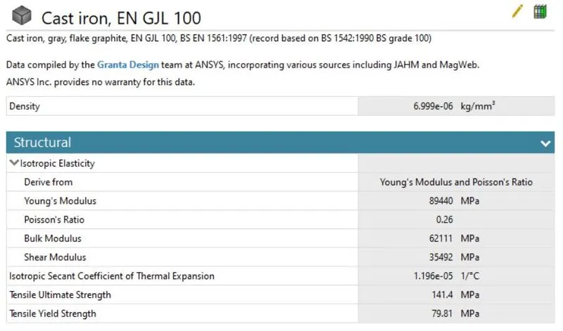
Cast iron:
Cast iron is a group of iron-carbon alloys with a carbon content of more than 2%. Its usefulness derives from its relatively low melting temperature. The chemical composition of cast iron as followsIron ~94%, Carbon 3.2 – 3.60%, Silicon 2.2 – 2.8%, Manganese 0.1 – 0.2%, Magnesium 0.03 – 0.04%, Phosphorus 0.005 – 0.04%, Sulfur 0.005 – 0.02%, Copper <= 0.40%.
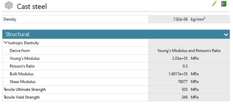
Cast steel:
Cast steel is a ferrous alloy with a maximum carbon content of approximately 0.75%. Steel castings are solid metal objects produced by filling the void within a mold with liquid steel. They are available in many of the same carbon and alloy steels that can be produced as wrought metals.
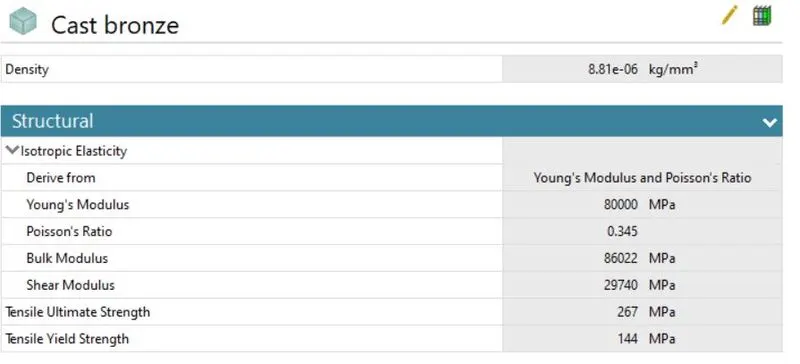
Cast bronze:
Bronze is an alloy typically composed of 90 percent copper and 10 percent tin, and, because it has a lower melting point than pure copper, it will stay liquid longer when filling a mold. It also produces a better casting than pure copper and has superior tensile strength.
Connections:
Contact:
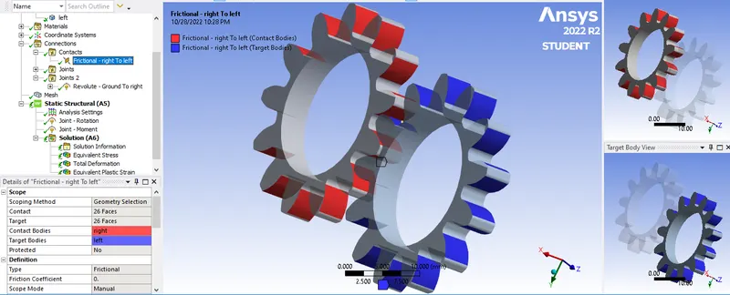
Here we need to create contact between the spur gears. Select the contact tab. Now select the tooth faces and select apply. Now assign type as frictional. Behavior as symmetric. Assign formulation as Augmented Lagrange. Treatment interface as adjust to touch.
JOINT:
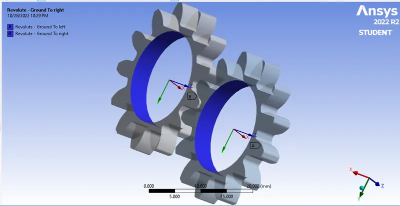
Now assign joint contact to the gears. Here right clk>Joint. Now assign the circular faces and connection type as Body-ground. And joint type as revolute Along Z-direction.
Meshing:
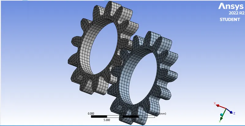
The meshing of the model will be automatically generated when solving the model. After that, we can edit the mesh element size to 1mm to reduce the time.
Analysis settings:
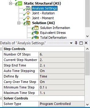
Now assign no. of. timesteps as 6 and assign large deflection tab as on. Initial time step as 0.2. Max time step as 0.5. Min time step as 0.05.
Defining Load:
joint load: Revolute
Now create a joint load for the geometry. For right gear, Right clk>insert>joint load. Now define DOF as rotation Z, Type as rotation, magnitude as tabular data. Now create tabular data as 30, 60, 90, 120, 150, 180. For left gear, define DOF as rotation Z, Type as moment, magnitude as tabular data. Now create tabular data as -10000N/mm.
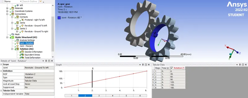
Joint movement:
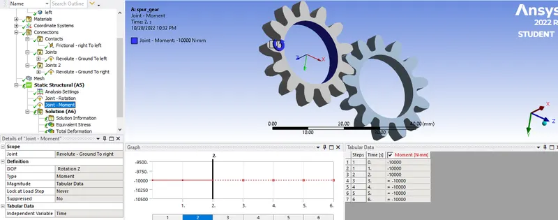
Defining Output results:
Now define outputs for the geometry using solution>right clk>insert>Total deformation, Von mises stress, stress intensity.
Results:
Case:1
Using Cast Iron(ductile) as a material,
Case:2
Using Cast Bronze as material,
Case:3
Using Cast Steel as material,
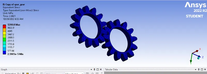
EQUIVALENT STRESS :
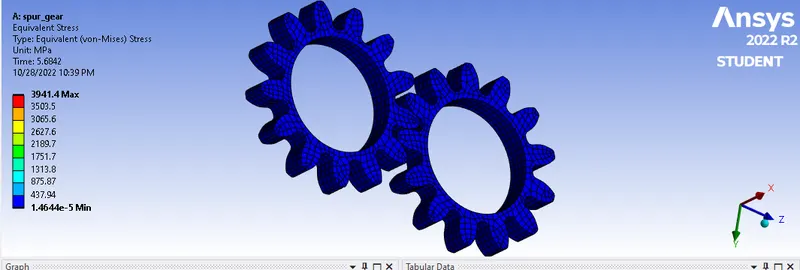 CASE :1
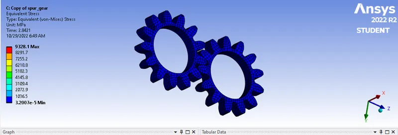 CASE 2
 CASE 3
TOTAL DEFORMATION
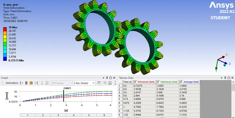 CASE 1
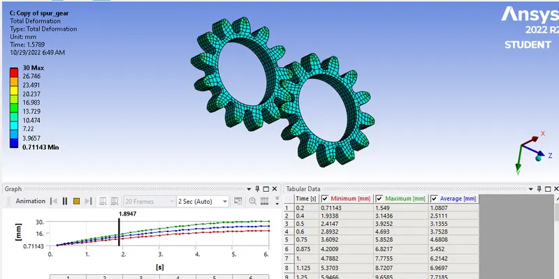 CASE 2
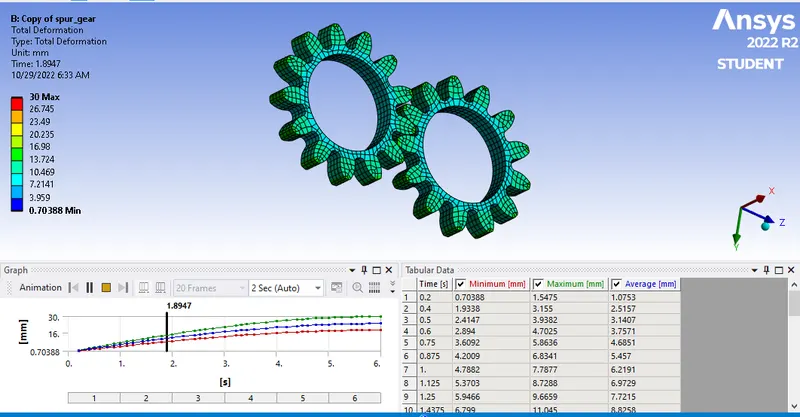 CASE 3
STRESS INTENSITY:
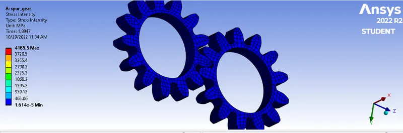 CASE 1
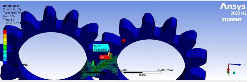 case 1 (cast iron)
maximum stress intensity 346.25 MPa at nodes 6626
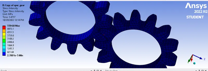 case 2
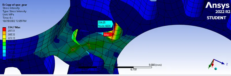 case 2 (bronze)
maximum stress intensity 334.05 MPa at nodes
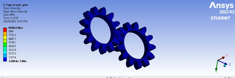 case 3
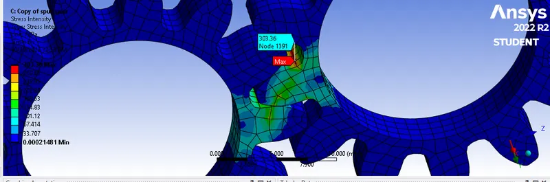 case 3 (cast steel)
maximum stress intensity 303.36 MPa at nodes 1391
Conclusion:-
|
MATERIAL |
CASE 1 (cast iron) |
CASZE 2 (cast bronze) |
CASE 3 (cast steel) |
|
TOTAL max DIFORMATION min |
30 mm 0.72575 mm |
30 mm 0.70388 mm |
30 mm
0.71140 mm |
|
EQUIVALENT STRESS max min |
3941.4 MPa 1.4644e-5 |
5200.8 MPa 2.5905e-5 |
9328.1 MPa 3.2007e-5 |
|
STRESS INTENSITY max min |
4185.5 MPa 1.614e-5 |
5594.4 MPa 2.7801e-5 |
9968.6 MPa 3.6804e-5 |
Here the maximum stress intensity has occurred at cast steel so that it may fail soon when compared with both cases. we have minimum stress intensity in the cast iron because it may have high durability and high strength mechanical properties. it can be used for manufacturing when compared with other cases. it is cost-effective.
We can see the maximum stress intensity area. the failure may occur in this area. finally, we can choose cast iron for the further process because it is cost-effective and easily accessible.
STRESS INTENSITY :
The crack size and shape, the specimen geometry and loading along with material fracture toughness (a measure of a material with pre-existing crack to resist fracture) can be use to determin the ability of the material to resist fracture. The importance of related geometry correction factor for complience the determination of stress intensity.