Week 1 Spur Gear Challenge
STATIC STRUCTURAL ANALYSIS ON SPUR GEAR USING ANSYS
OBJECTIVE:
To carry out a static structural analysis on spur gear with following type of materials,
- Case-1: Cast Iron
- Case-2: Cast Bronze
- Case-3: Cast Steel
To find and compare the results of Equivalent stress, Total deformation, Stress intensity for all the cases.
To recommend the choice of material based on the results.
THEORY-
1.1 Spur Gear:
- Gears are defined as toothed wheels or multilobed cams, which transmit power and motion from one shaft to another by means of successive engagement of teeth. Gears are broadly classified into four groups, viz., spur, helical, bevel and worm gears. A pair of spur gears is shown in Fig.
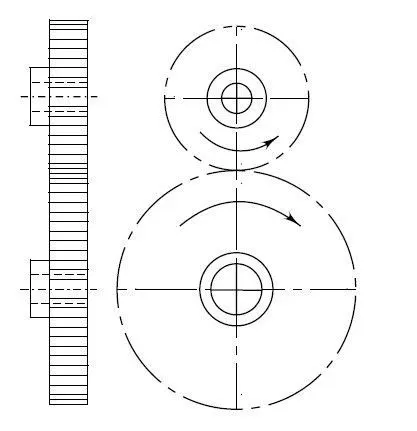
- In case of spur gears, the teeth are cut parallel to the axis of the shaft. As the teeth are parallel to the axis of the shaft, spur gears are used only when the shafts are parallel. The profile of the gear tooth is in the shape of an involute curve and it remains identical along the entire width of the gear wheel. Spur gears impose radial loads on the shafts.
Gear Tooth Failures:
- There are two basic modes of gear tooth failure breakage of the tooth due to static and dynamic loads and the surface destruction. The complete breakage of the tooth can be avoided by adjusting the parameters in the gear design, such as the module and the face width, so that the beam strength of the gear tooth is more than the sum of static and dynamic loads. The surface destruction or tooth wear is classified according to the basis of their primary causes. The principal types of gear tooth wear are as follows:
- Abrasive Wear
- Corrosive Wear
- Initial Pitting
- Destructive Pitting
- Scoring
Selection of Material:
The desirable properties of gear material are as follows:
(I) The load carrying capacity of the gear tooth depends upon the ultimate tensile strength or the yield strength of the material. When the gear tooth is subjected to fluctuating forces, the endurance strength of the tooth is the deciding factor. The gear material should have sufficient strength to resist failure due to breakage of the tooth.
(ii) In many cases, it is ‘wear rating’ rather than ‘strength rating’ which decides the dimensions of the gear tooth. The resistance to wear depends upon alloying elements, grain size, percentage of carbon, and surface hardness. The gear material should have sufficient surface endurance strength to avoid failure due to destructive pitting.
(iii) For high-speed power transmission, the sliding velocities are very high and the material should have low coefficient of friction to avoid failure due to scoring.
(iv) The amount of thermal distortion or warping during the heat treatment process is a major problem in gear applications. Due to warping, the load gets concentrated at one corner of the gear tooth. Alloy steels are superior to plain carbon steels in this respect, due to consistent thermal distortion.
- Gears are made of cast iron, steel, bronze and phenolic resins. Large size gears are made of grey cast iron of Grades FG 200, FG 260 or FG 350. They are cheap and generate less noise compared with steel gears. They have good wear resistance. Their main drawback is poor strength. Case-hardened steel gears offer the best combination of a wear resisting hard surface together with a ductile and shock- absorbing core. The plain carbon steels used for medium duty applications are 50C8, 45C8, 50C4 and 55C8. For heavy duty applications, alloy steels 4OCrl, 30Ni4Cr1 and 4ONi3Cr65Mo55 are used.
- Although steel gears are costly, they have higher load carrying capacity. Bronze is mainly used for worm wheels due to its low coefficient of friction and excellent conformability. It is also suitable where resistance to corrosion is an important consideration in applications like water pumps. Their main drawback is excessive cost.
ANALYSIS SETUP
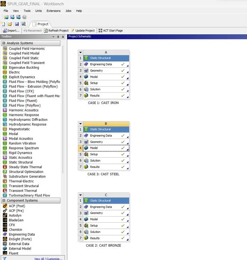
Geometry:
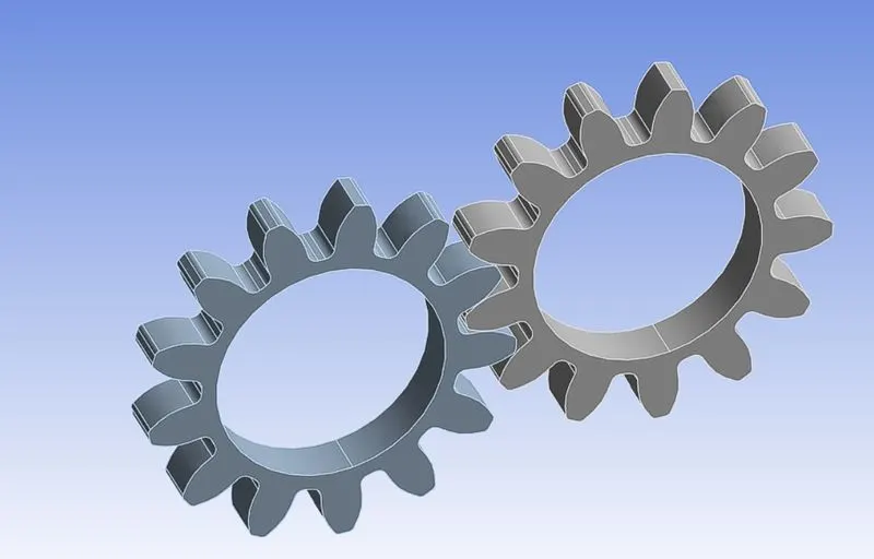
- The given 3D model of spur gear is imported into ANSYS Workbench for static structural analysis system. The spur gear has 13 teeth with driver gear being named as right gear and driven gear being named as left gear.
Material Properties:
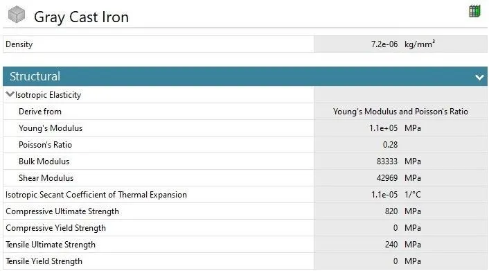
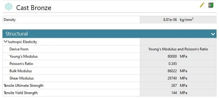
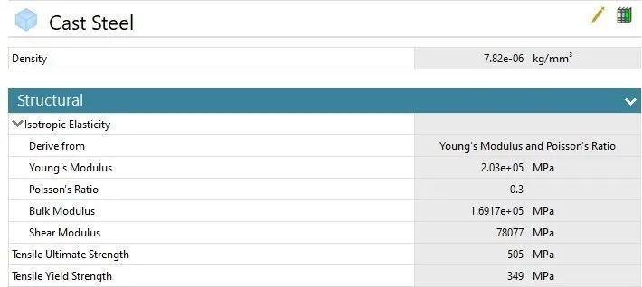
The materials used for spur gear analysis is as shown above, The analysis is carried out for each cases of material individually i.e.,
- Case-1: Cast Iron
- Case-2: Cast Bronze
- Case-3: Cast Steel
Note: The analysis setup for case-1 is demonstrated.
Connection Details:
- Contact details:
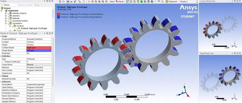
Frictional contact of spur gear.
- The type of contact between the faces of driver and driven gear teeth is defined as frictional contact with contact bodies being right gear and target bodies being left gear. Augmented Lagrange formulation is chosen to minimize the interference errors. Interface treatment is chosen as adjust to touch to avoid penetration.
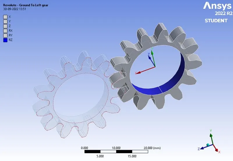
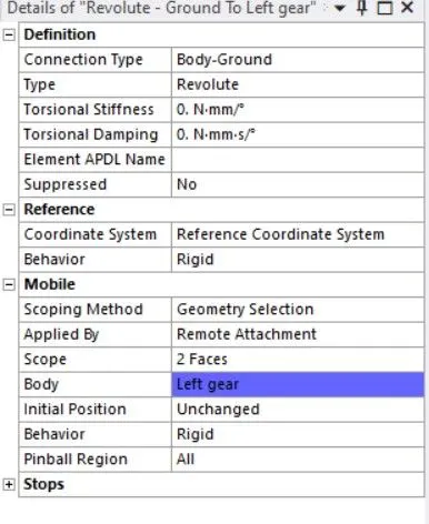
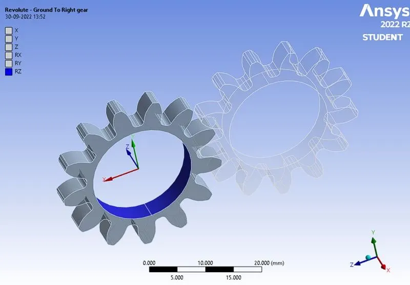
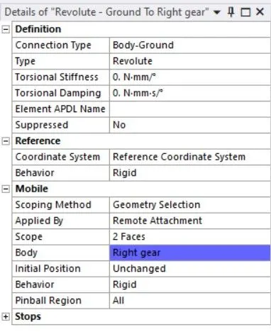
Revolute Joint of spur gear .
- The left and right gears are specified with revolute type of joint having rotation about Z-axis with connection type being body-ground.
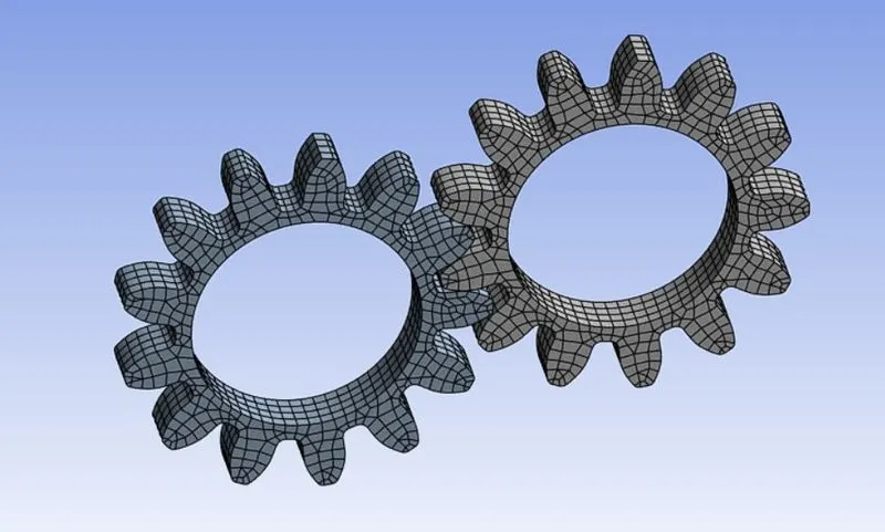
Meshing:
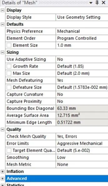
Analysis settings:
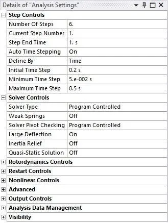
- The total number of steps for analysis is specified as 6 with auto time stepping being ‘On’. The initial, minimum and maximum time step is specified as 0.2 s, 5e-2 s and 0.5 s respectively. In the solver controls, the large deflection is set to ‘On’
Joint loads details:
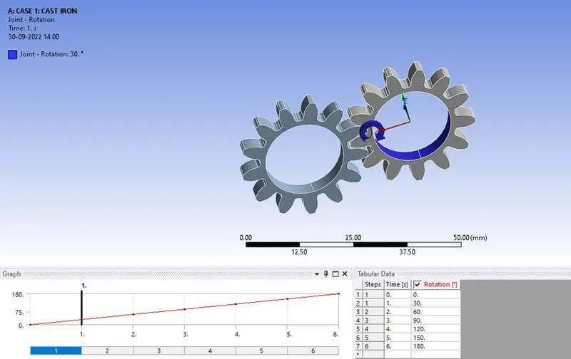
- The left gear is the driven gear hence, rotation (clockwise) for 1800 is specified with an increment value of 300 for each step.
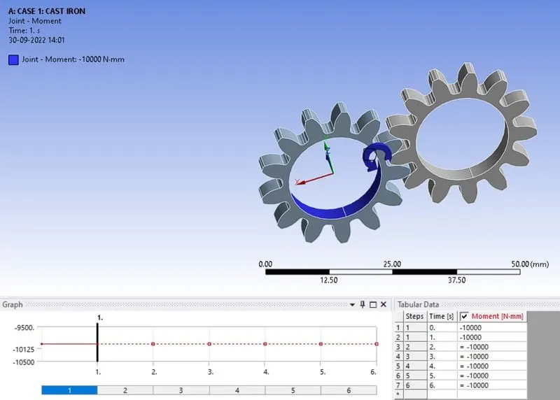
- The right gear is the driver gear hence, moment (anti-clockwise) of -10 N-m is specified for all the steps.
RESULTS-
1 Total Deformation:
- Case-1: Cast Iron
- Case-2: Cast Bronze
- Case-3: Cast Steel
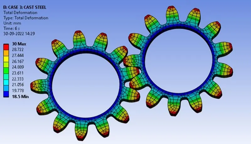
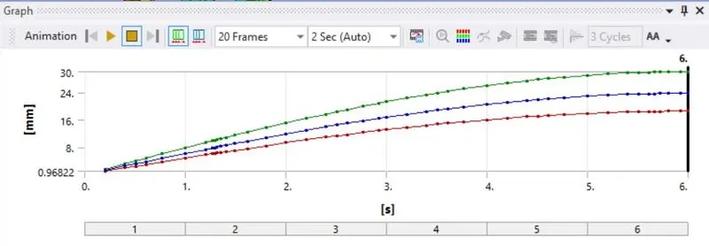
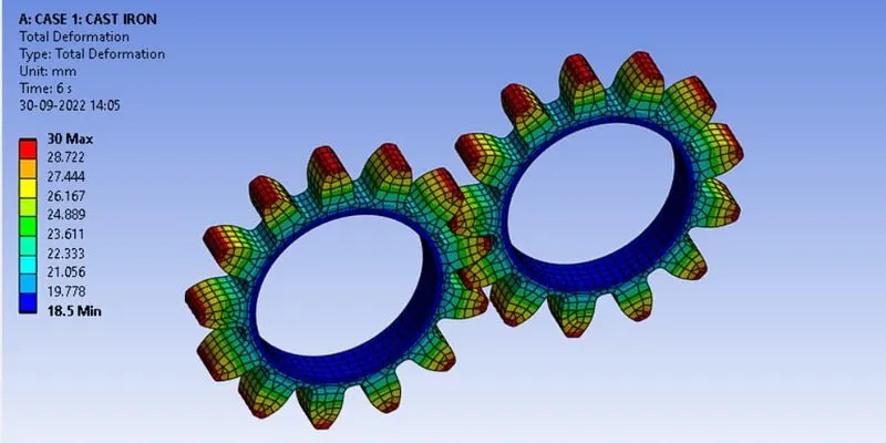
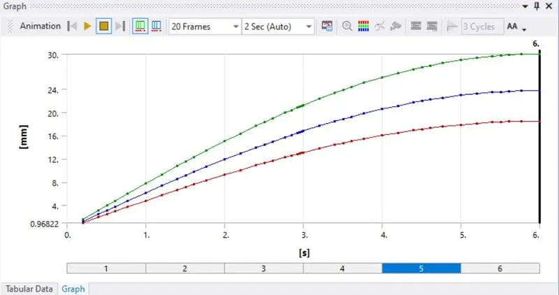
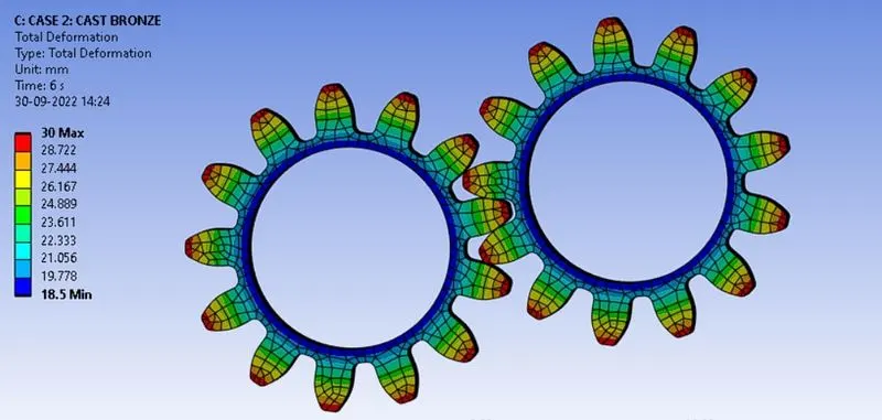
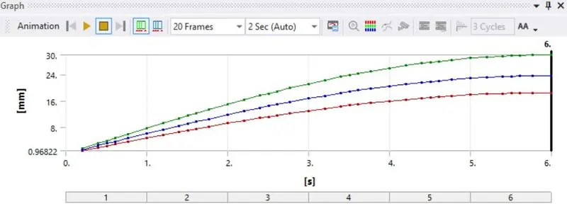
- From the deformation contour plot for all the cases, it is observed that the maximum deformation of 30 mm has occurred at the outer edges of the teeth of spur gear.
2 Equivalent stress distribution:
- Case-1: Cast Iron
- Case-2: Cast Bronze
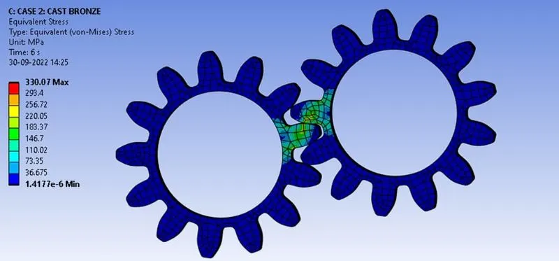
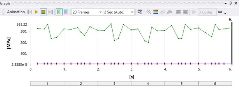
- Case-3: Cast Steel
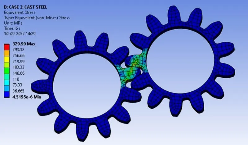
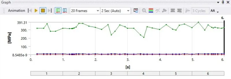
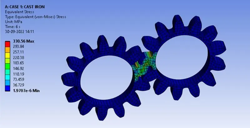
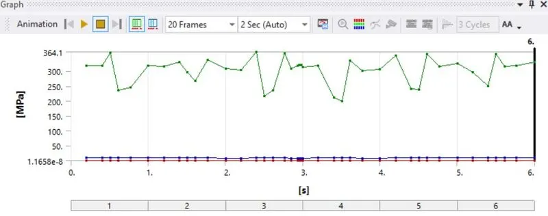
- From the v-m stress contour plot for all the cases, it is observed that the maximum stress is developed at the interface of face and flank of the spur gear teeth.
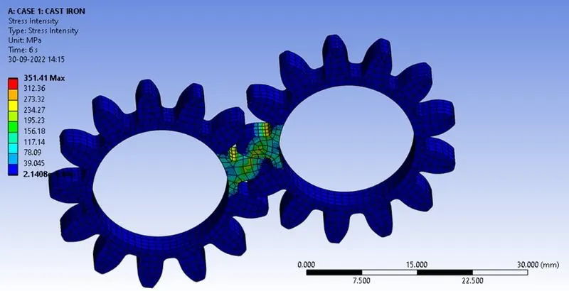
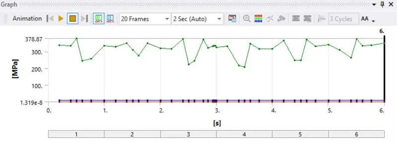
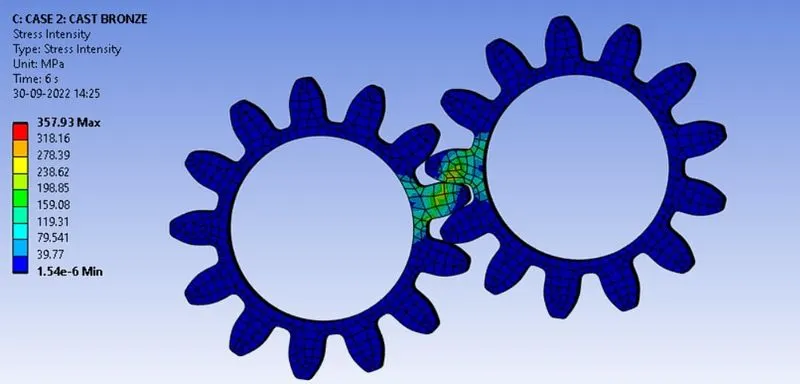
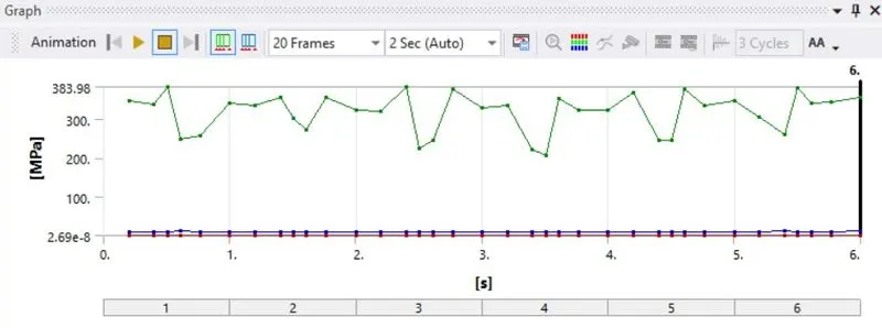
3 Stress Intensity:
- Case-1: Cast Iron
- Case-2: Cast Bronze
- Case-3: Cast Steel
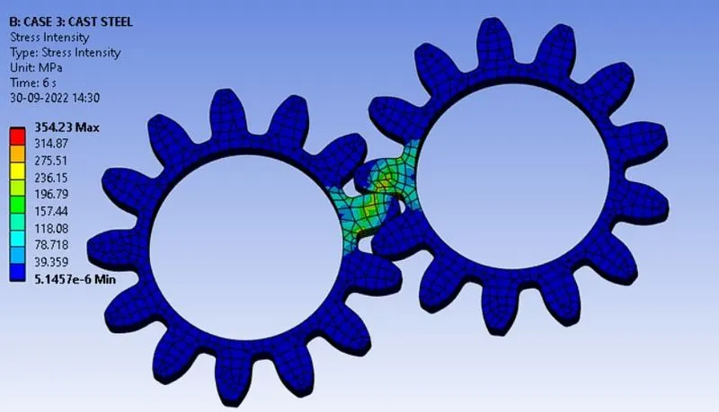
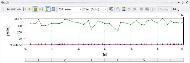
- From the stress intensity contour plot for all the cases, it is observed that the maximum stress is developed at the interface of face and flank of the spur gear teeth
Comparison of Results:
- The maximum and minimum values of total deformation, v-m stress and stress intensity is tabulated as shown below.
|
Materials |
Total Deformation (mm) |
Equivalent Stress (MPa) |
Stress Intensity (MPa) |
|||
|
Max. |
Min. |
Max. |
Min. |
Max. |
Min. |
|
|
Case-1: Cast Iron |
30 |
18.5 |
330.56 |
1.97e-6 |
351.41 |
2.14e-6 |
|
Case-2: Cast Bronze |
30 |
18.5 |
330.07 |
1.41e-6 |
357.93 |
1.54e-6 |
|
Case-3: Cast Steel |
30 |
18.5 |
299.99 |
4.51e-6 |
354.23 |
5.145e-6 |
- From the table, it is observed that the maximum and minimum value of total deformation is 30 mm and 18.5 mm respectively for all the cases of spur gear.
- The maximum value of Equivalent stress developed in cast steel spur gear is least i.e., 299.99 MPa whereas, the maximum Equivalent stress developed in cast Iron spur gear is highest i.e., 330.56 MPa. Hence, based on traditional strength of materials approach i.e., from the results of Equivalent stress and Total deformation for all the cases of spur gear, case-3: Cast steel is the preferred choice of material.
- The maximum value of stress intensity developed in cast Bronze spur gear is highest i.e., 354.23 MPa whereas, the maximum stress intensity developed in cast iron spur gear is least i.e., 351.41 MPa. The stress intensity is nothing but failure stress due to fracture. The higher value of stress intensity indicates that the material has more service life. Based on fracture mechanics approach i.e., from the results of Stress intensity for all the cases of spur gear, case-3: Cast Bronze is the preferred choice of material.
Case-1: Cast Iron spur gear are cheap and generate less noise compared to other gears. They have good wear resistance. From the analysis results it has moderate values of stress intensity and equivalent stress. Hence, the recommended choice of material is Cast Iron.
Animation of Results: Uploaded in Drive (refer below link)
https://drive.google.com/drive/folders/1Morl4uSdy7FhiRFjNqvN64VlHhMEXqIw?usp=sharing
CONCLUSION
- Static structural analysis was carried out successfully on spur gear having following type of materials,
Case-1: Cast Iron
Case-2: Cast Bronze
Case-3: Cast Steel
- Based on traditional strength of materials approach i.e., from the results of Equivalent stress and Total deformation for all the cases of spur gear, case-1: Cast Iron is the preferred choice of material.
- Based on fracture mechanics approach i.e., from the results of Stress intensity for all the cases of spur gear, case-2: Cast Bronze is the preferred choice of material.
- The recommended choice of material is Cast Iron.(Cast Iron spur gear are cheap and generate less noise compared to other gears. They have good wear resistance. From the analysis results it has moderate values of stress intensity and equivalent stress. Hence, the recommended choice of material is Cast Iron.)