Week 1 Spur Gear Challenge
AIM :
Desing spur gear and evaluate the all results using ansys workbench.
SPUR GEAR :
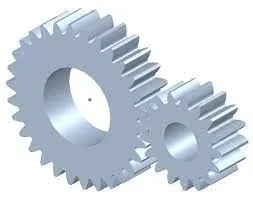
The spur gear is a cylindrically shaped tooth component that is used in industrial plants to transmit mechanical movements and to control speed, power, and torque. These simple gears are inexpensive, durable, reliable, and provide constant speed positive drive to facilitate day-to-day industrial operations. Spur gear are used in mechanical aplication to increase to decrease the speed of a device or multiply torque by transmitting motion and power from one shaft to another througha series of mated gears.
Spur gear or straight-cut gears are the simplest types of gear. They consist of a cylinder or disk with teeth projecting radially. Although the teeth are not straight, usually having a special shape to achieve a constant drive ratio that is mainly involute but less often cycloidal, the edge of each tooth is straight and parallel to the axis of rotation.
Spur gears are more efficient compared to helical gears with the same size. They are quite reliable and offer constant velocity. Spur gear are also considered a member posittive transmission because they don't have any slippage. gears can serve as efficient meansto reverse the directon of motion, change rotational speed or to change which axis rotary motion is occurring on. The sizes of the gears usually depend on the desried gear ratio and the shaft upon whichthe gear will be mated.
- Case 1:
Using Cast Iron(ductile) as a material, carry out a static structural analysis to find out Equivalent stress, Total deformation and Stress intensity(Learn about what stress intensity is).
PROCEDURE:
- Get static structure from analysis system.
- in Engineering data select Granta Sample Materials.
- From the material list, add material Cast iron(Ductile),Cast steel, or Cast Bronze as per case to be analyzed.
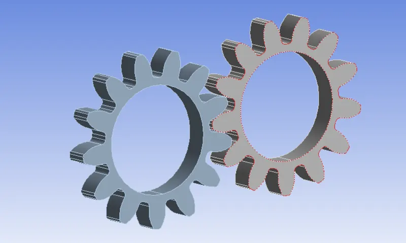
- After selecting material import geomatry as Skill_Lync_Gear.stp.
- Go to the model.
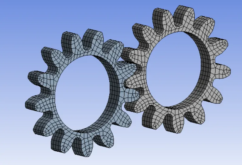
- Create mesh 1mm element size as shown.
- Select the geomatry of both gears and rename as Right And Left.
- Give material assignment to both gears as per case.
- From the project tree, select connection and create contacts.
Geometry
Mesh
Contacts
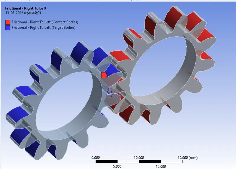
- For defining contacts between two gears, select faces of left gear as contacts and faces of right gear as Target for connection.
- There are 26 faces of each gear must be selected.
- Select contact type = Frictional. because due to friction, there will be movement between gears.
- Select behavior = symmetric
- Select formation = Augmented legrange. As soon as teeth come in contact, it will tend to move from position so Augmented Legrange formation reduces vinration and penetration stiffness of gears.
- Select interface Treatment = Adjust to touch because if there is a gap between them or initial penetration than this setting will help to adjust it and any error can be avoided.
- Select inner face of each gear and give it revolute joint as descriped in above image.
- For frame of reference for gear select connection type = Body To Ground for both of the gears.
- We can see that in revolute joint, degree of freedom for gears automatically set to its axis in RZ direction.
BOUNDARY CONDITIONS:
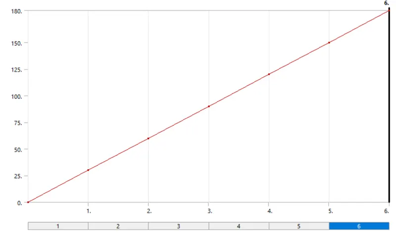
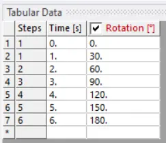
- Here we are going to look at contacts forces, traces and stress developed for 1 revoiution of gear. So for 180 degree angle in analysis setting give values as given below
No steps = 6
Auto time Stepping = ON
Defined by = TIME
initial Time Step = 0.2 s
Minimum Time Step = 5 e-2 s
Maximum Time Step = 0.5
- Select all 6 steps and select Large Deflection = ON in slover controls.
- other Bountry condition for joint are as given below
- joint load
Joint Rotation = Ground To Left
Type = Rotation
Magnitude = Tabular Data
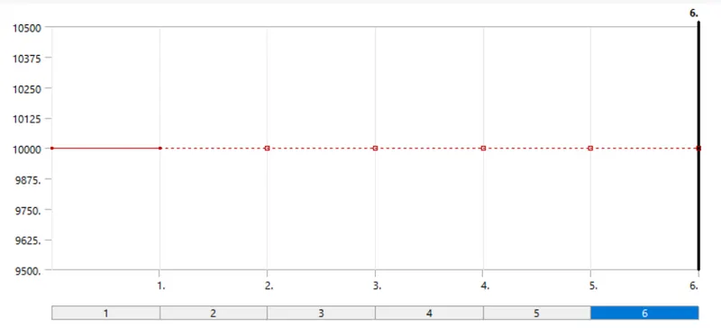
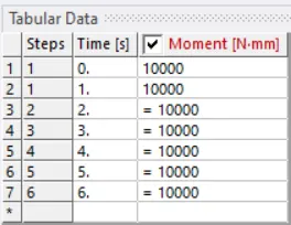
- Joint Load
Type = Moment
Magnitude = Tabular data
Tabular data
SOLUTION:
- After giving proper boundary condition create desired solution for output results.
- Create solutions for Equivalent srtess, Total deformation and Stress intensity
- Also give contact tool and create solution for contact status and pressure.
RESULTS :
Results for all cases
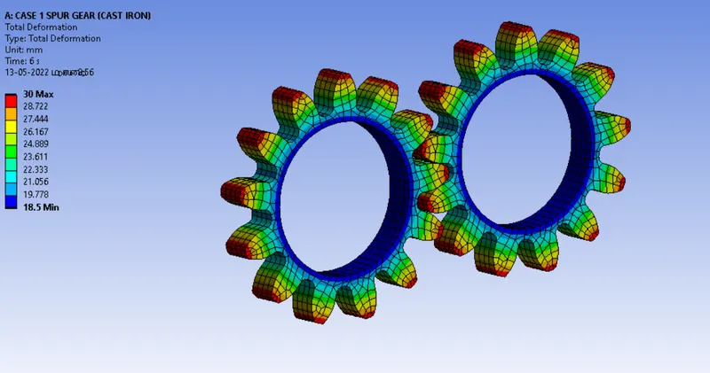
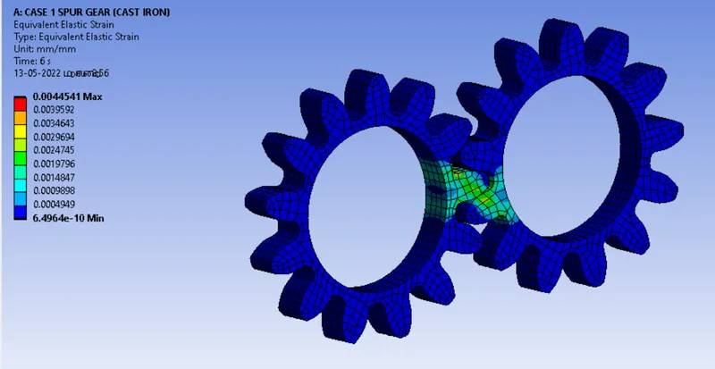
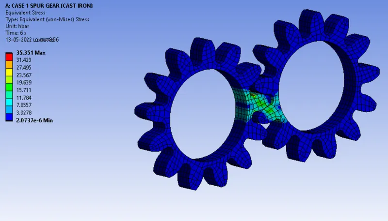
Cas1 : casrt iron
TOTAL DEFORMATION
STRAIN
STRESS
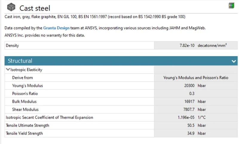
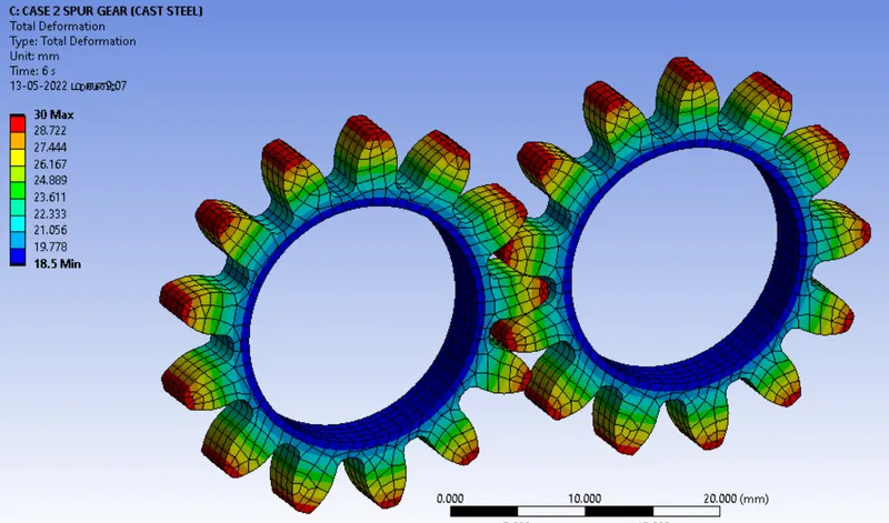
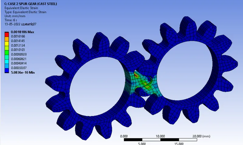
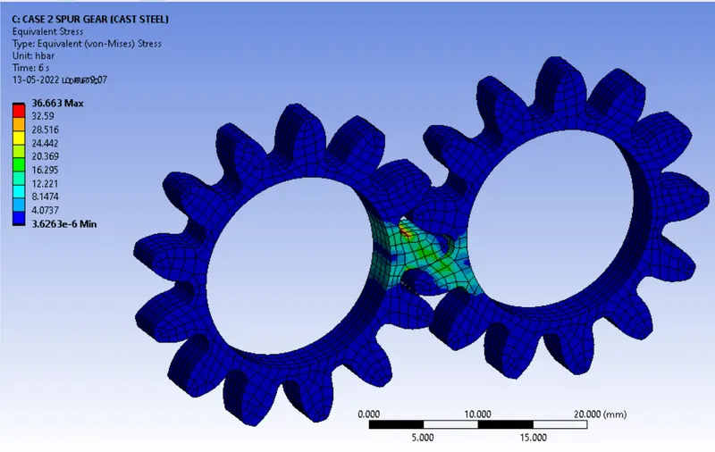
CASE 2 : CAST STEEL
MATERIAL
TOTAL DEFORMATION
SRTAIN
STRESS
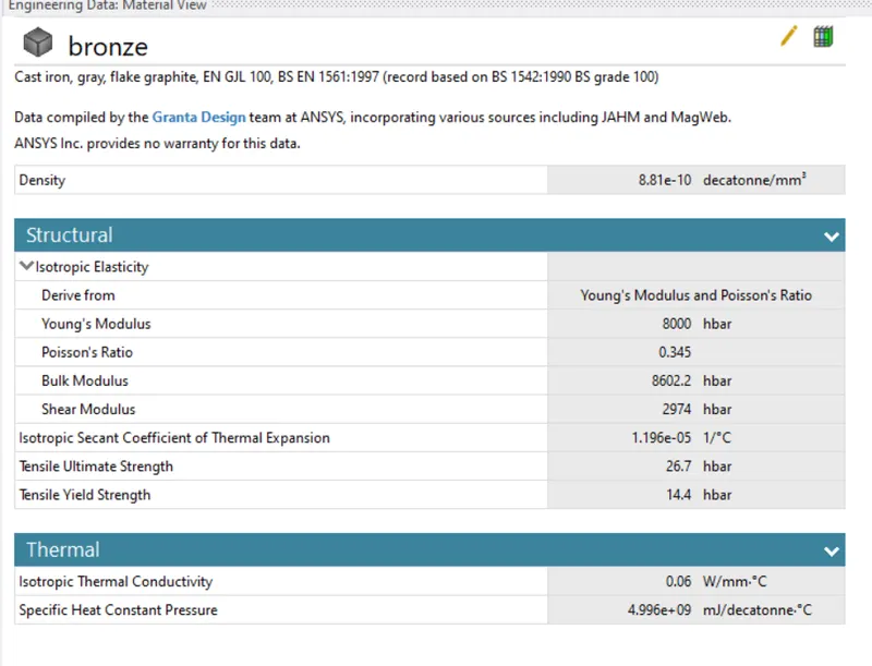
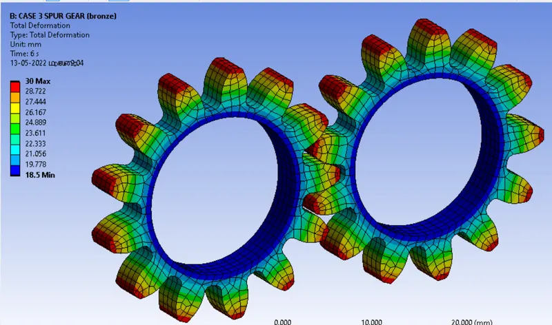
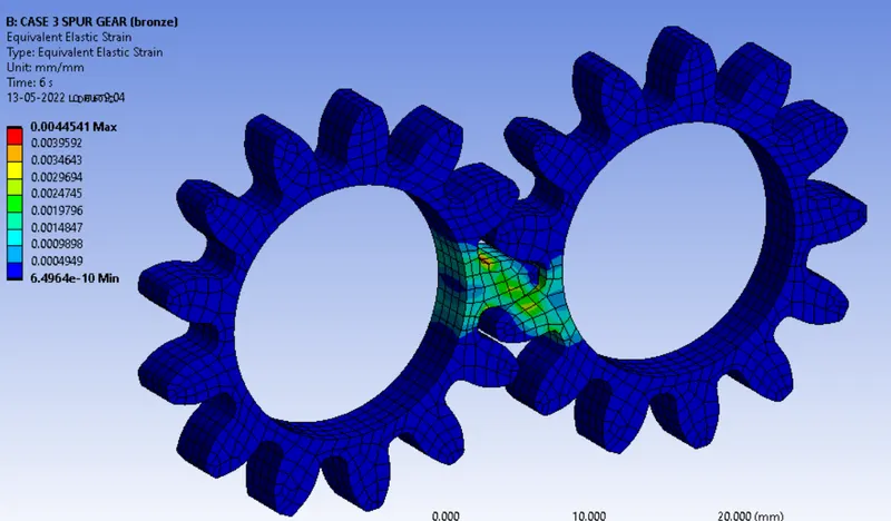
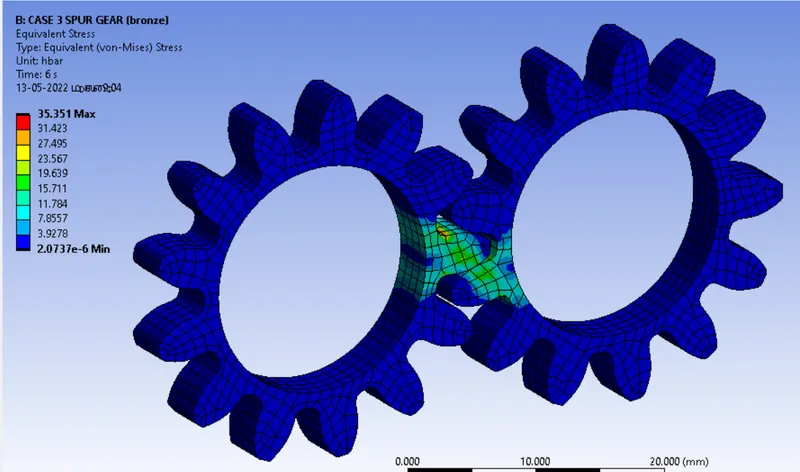
CASE 3 : BRONZE
MATERIAL
TOTAL DEFORMATION
STRAIN
STRESS
CONCLUSION
Three materials are have their own mechanical properties
- Cast iron materials is a good vibration adaptor and mostly it is used in the lathe gears transmission system.
- Carbon steels are widly used in the big gear boxes.
- Bronze is a expansive material compared to others and it is used to wormgear boxes it is not suitable for the heavy operations because it will easily damage while giving load.
- Analysis stand point we can choose bronze as a material for gears.
CASE 1
https://drive.google.com/drive/folders/1-JWODXpYsy2i3ne5_kT3JUh5AeSt8CD_?usp=sharing
CASE 2
https://drive.google.com/drive/folders/1l0UwmfYBwIbX2cnwdjVA-0kkvI_xm7Y1?usp=sharing
CASE 3
https://drive.google.com/drive/folders/1m7osRJK2gEB60elaRnssX7oxpuY_sBO3?usp=sharing
SPUR GEAR ZIP FILE
https://drive.google.com/file/d/10p_3q1YMFfEuHZfcicsEkWb_UY3YzLR2/view?usp=sharing