Week 1 Spur Gear Challenge
SPUR GEARS
Aim:
To set up a simple spur gear system using 3 different materials , Bronze cast iron and cast steel, and determine the best material to proceed with for manufacture
Theory
Spur Gears
Spur gears are one of the most popular types of precision cylindrical gears. These gears feature a simple design of straight, parallel teeth positioned around the circumference of a cylinder body with a central bore that fits over a shaft. In many variants, the gear is machined with a hub which thickens the gear body around the bore without changing the gear face. The central bore can also be broached as to allow the spur gear to fit onto a spline or keyed shaft.
Spur gears are used to transfer motion and power from one shaft to another in a mechanical setup. This transference can alter machinery’s operating speed, multiply torque, and allow for the fine-tuned control of positioning systems. Their design makes them suitable for lower speed operations or operational environments with a higher noise tolerance.
Some of the typical industrial applications include:
- Transmissions
- Conveyor systems
- Speed reducers
- Engines and mechanical transportation systems
- Gear pumps and motors
- Machining tool
Stress Intensity
The stress intensity factor, K, is used in fracture mechanics to predict the stress state or stress intensity near the tip of a crack or notch caused by a remote load or residual stresses.It is a theoretical construct usually applied to a homogeneous, linear elastic material and is useful for providing a failure criterion for brittle materials, and is a critical technique in the discipline of damage tolerance. The concept can also be applied to materials that exhibit small-scale yielding at a crack tip.
Procedure
- In Ansys workbench, edit the engineering data sources and add the 3 materials to be used for each case.
- Cast iron is available in the Ansys Granta Material Sample Data set but it is required to create the material model for cast steel and cast bronze
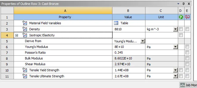
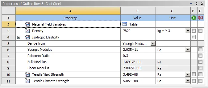
Note:The other material properties such as coefficient of thermal expansion need not be defined for this test as thermal stresses are negligible in this case.
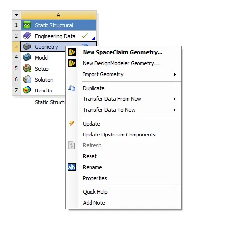
- After this, you can open the geometry in space claim by right clicking and importing the model from workbench
- Now open the geometry in mechanical by double clicking the model icon.
- In mechanical, we can start by defining the contact regions.
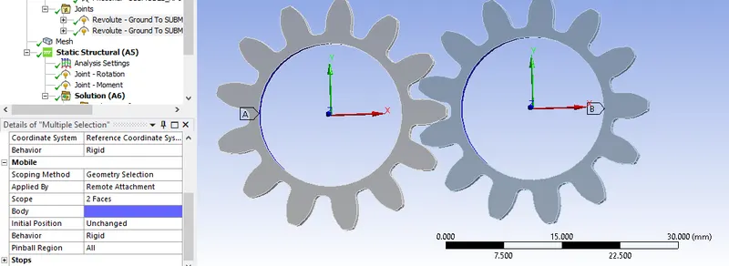
- Each gear has 13 teeth so, you need 26 faces in both target and contact.
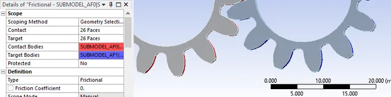
- Select the opposite faces of each face by control clicking them.
- Create revolute joints at the centre of each gear.
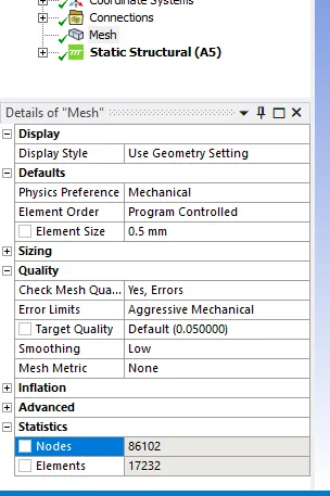
- For meshing, set an element length of 0.5mm (this can be reduced or increased according to your requirements).
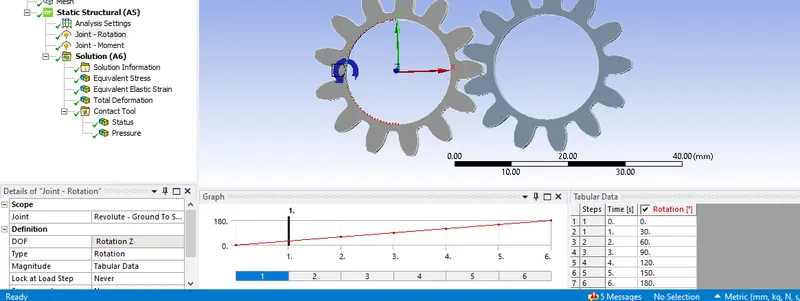
- Now create your boundary conditions.
- Create a joint load and set it accordingly
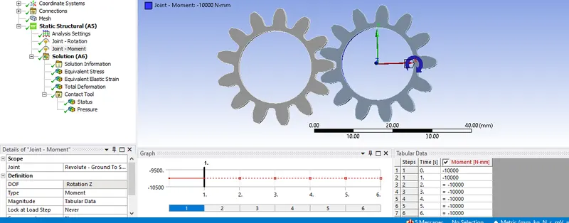
- For the other gear, create a moment.
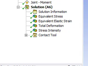
- Create the appropriate output blocks (this can be created after running the solution as well)
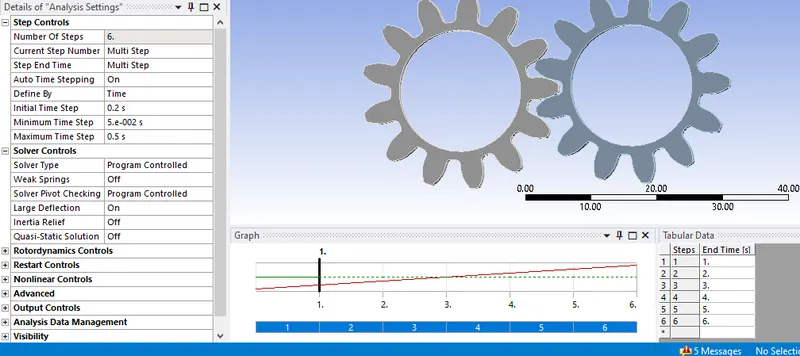
- Before running, make sure your solver settings are as shown.
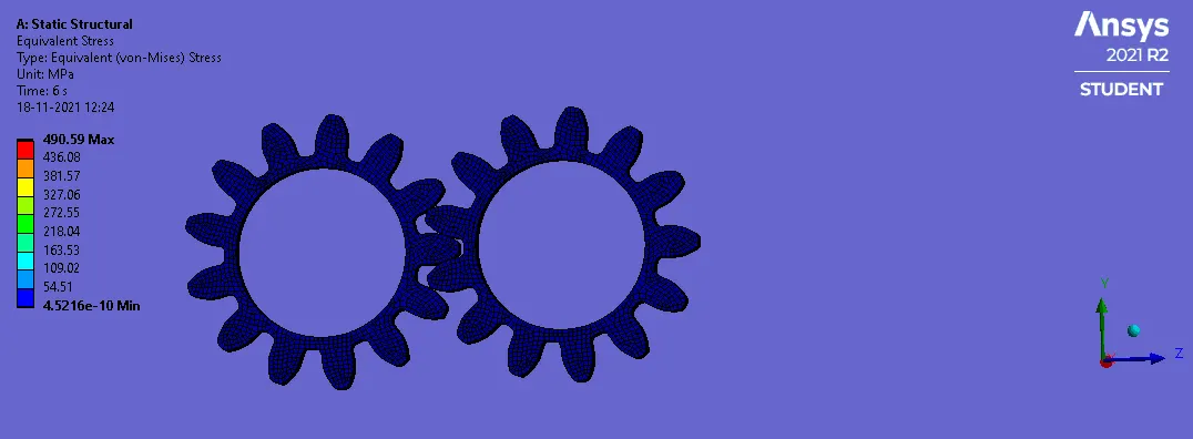
- After this run the simulation for each material case check your contours.
Post Processing
Case 1:Cast Iron
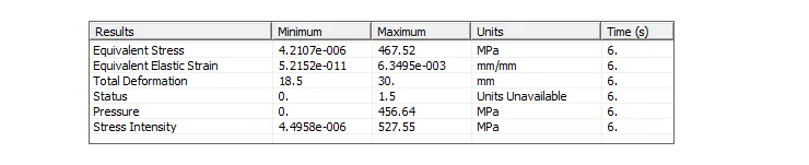
Case2: Bronze
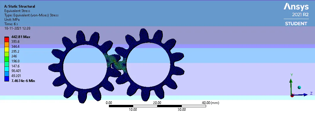
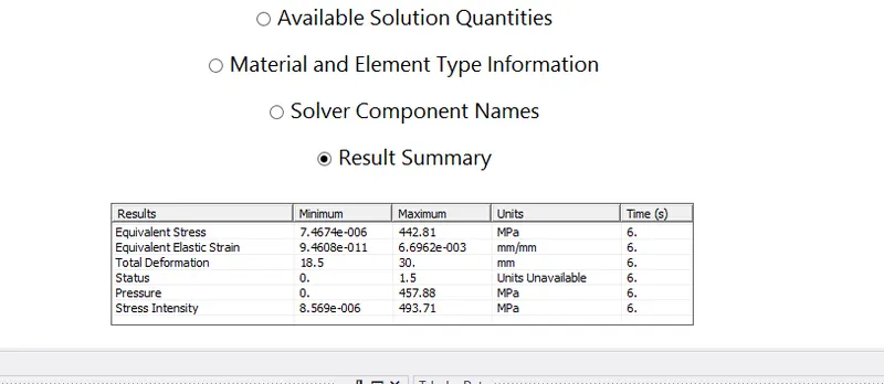
Case 3:Steel
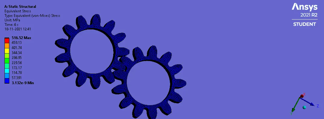
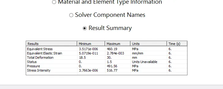
Tabulating the Results for Each Case
| Case | Cast Iron | Cast Bronze | Cast Steel |
| Maximum Equivalent Stress (MPa) | 490.51 | 456.33 |
516.52 |
| Maximum Equivalent Strain | 0.0075862 | 0.0077861 | 0.0043571 |
| Maximum Pressure (MPa) | 680.61 | 654.61 | 850.84 |
| Maximum Stress Intensity (MPa) | 560.3 | 516.33 |
588.57 |
Note:Minimum Stress and strain are not included as they are very small (in the 10^-10 to 10^-14 range and thus can be assumed to be 0)
It can be observed that the maximum stress is seen in Cast steel,516.52Mpa with a significantly higher pressure of 850.84MPa and a stress intensity of 588.57MPa..This is unideal as it indicates low life of the component as the higher stresses signify lower fatigue life compared to cast iron or bronze.Thus we can conclude that cast steel will not be ideal despite its lower strain values.
Now comparing Bronze and Cast Iron, it can be seen that the stresses involved in Bronze is lower than that seen in Cast iron with pretty much similar strain observed and thus bronze should be more ideal for this case.However it should be noted that the difference in ease of manufacture between cast iron and cast bronze is significant as bronze is more expensive and more difficult to machine.This along with the insignifcant difference in stress and pressure make cast iron the more desirable material of choice as despite its higher stress intensity (approximately 44Mpa difference) it more than makes up for it in terms of manufacturing.
Conclusion
Spur gears are one of the most popular types of precision cylindrical gears and are used in mechanical applications to increase or decrease the speed of a device or multiply torque by transmitting motion and power from one shaft to another through a series of mated gears.
In this project, we compared the difference of stress, strain, pressure and stress intensity of a simple spur gear system with 3 different Materials (Cast Iron,Bronze and Cast Steel) with a static structural analysis and determined that Cast iron was the more desirable material of choice due to its ease of manufacture compared to bronze.
Of course the application of the gear also determines the type of material to be used as all 3 materials have their own applications.Cast iron provides durability and ease of manufacture(ideal for low velocity loads), Cast steel provides easier fabrication(better for high velocity loads), strong working loads and vibration resistance and Bronze spur gears are used in other devices where they are required to mate with steel spur gears(with much lower friction compared to steel-steel contacts).