Week 1 Spur Gear Challenge
Spur Gear Structural analysis
Aim : To perform structural analysis on a spur gear
Software: Ansys 2021 R1
Summary
Objectives
Procedure for case setup
Results
Errors encountered
Conclusion
Objectives:
- To carry out a static structural analysis on a spur gear to find out Equivalent stress, Total deformation and Stress intensity using different materials and
- To identify possible fracture location
PROCEDURE FOR CASE SETUP:
- Open ANSYS>>Drag and drop static structural model in the project schematic window.
- Go to the engineering data. Select gray cast iron material. For the remaining two materials, Let’s define them by using the given data as follows:
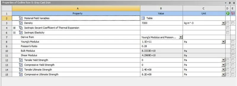
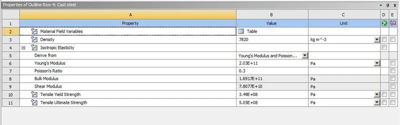
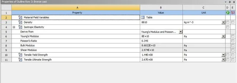
3. Go to the model tab for the meshing and the case setup.
4. In the Geometry rename the gear using a convenient name of our choice so that to make easy the identification while assigning the boundary conditions. Here let’s rename them as right gear and left gear respectively.

5.Go to contacts>>Define a frictional contact between the two gears as required: (following figure)
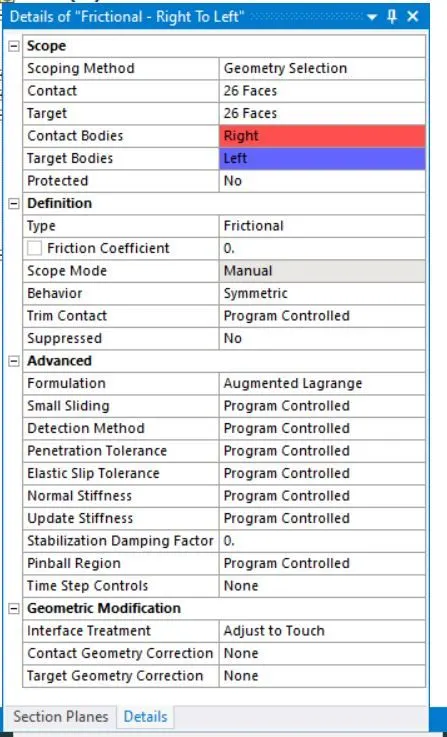
6. The next step is about to define the joints for the gears. The revolute joint is defined for the two gears using the body to ground option in the joint option as shown in the 8th Step
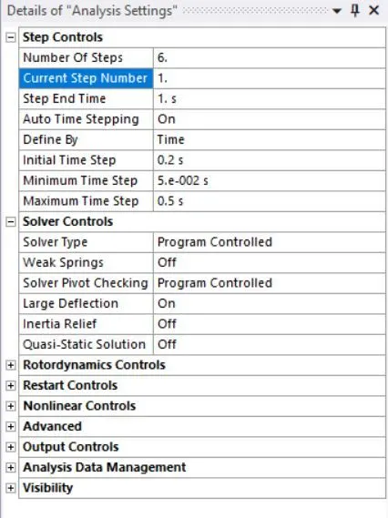
7. The following analysis settings are defined for the simulation.
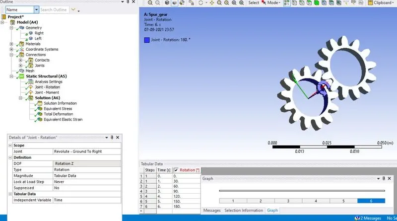
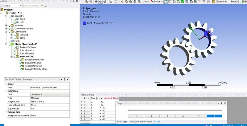
8. The joint load are defined in the figure below. For the left gear, rotation is defined and for the right gear, moment is defined.
9. From the solution option the results for total deformation, equivalent stress, and stress intensity are requested.
10. From the analysis settings, hit on solve to start the simulation.
11. The simulation has to be carried out for all the materials simply by changing the materials in the geometry tab.
Results:
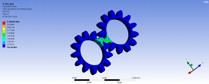
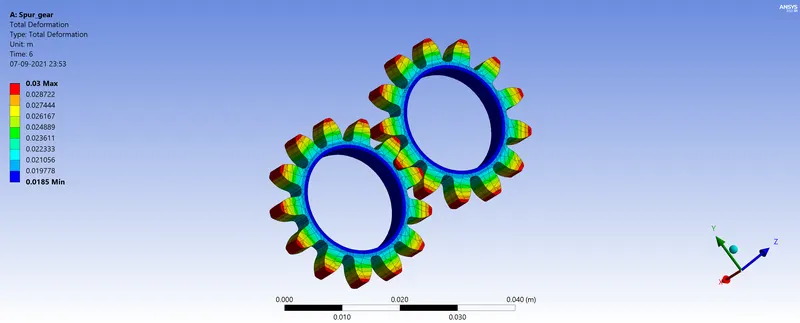
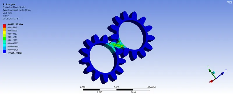
For Case 1: Cast iron
Animation:
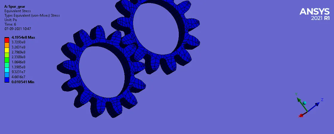
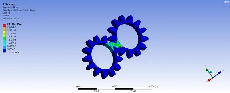
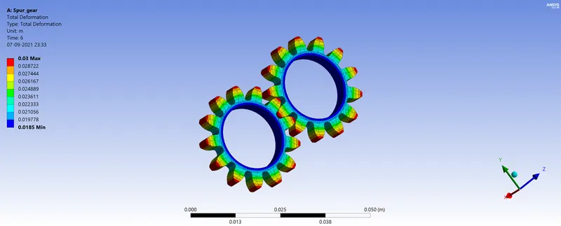
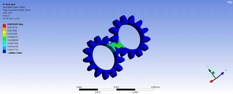
For case 2: Cast steel
Animation:
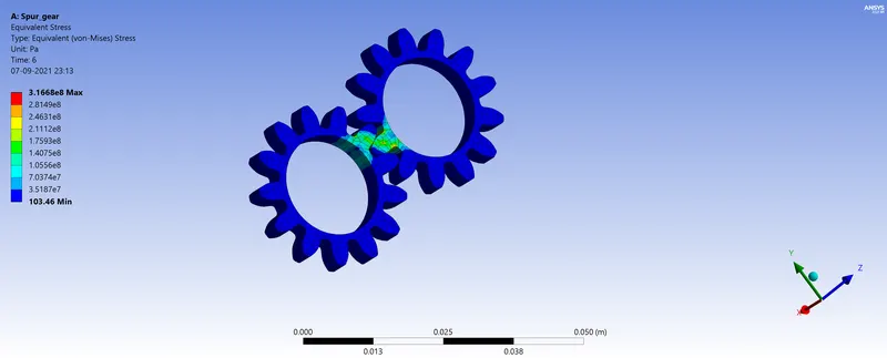
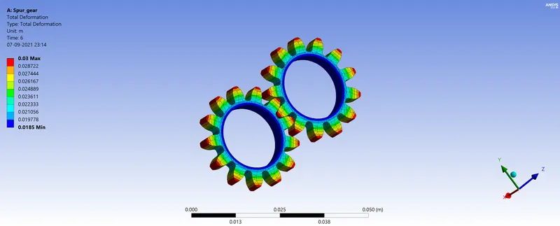
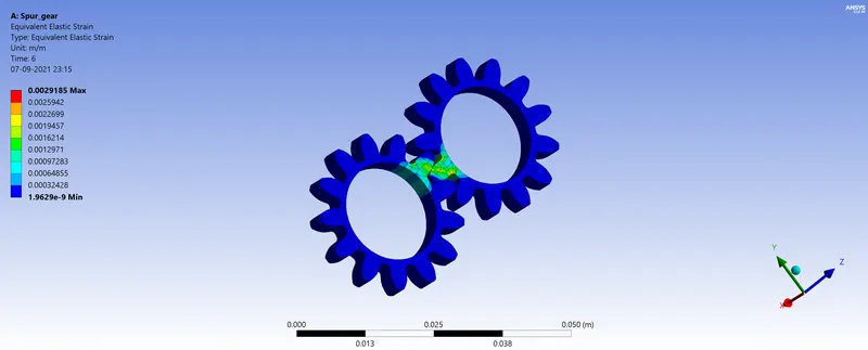
For case 3: Cast Bronze
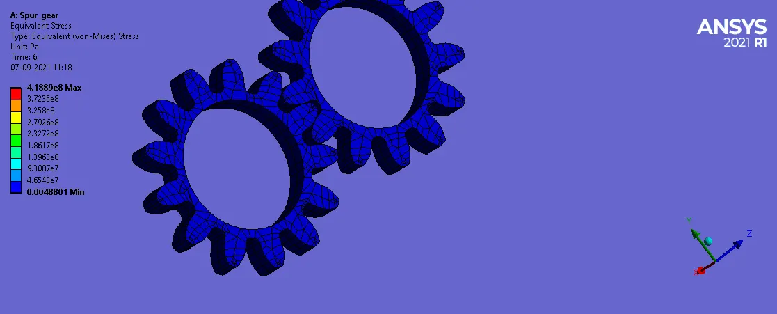
Animation:
Comparison:
|
Material |
Total Deformation (in m) |
Equivalent Stress (in MPa) |
Stress Intensity (in MPa) |
|
Gray Cast Iron |
0.03 |
316.00 |
417.13 |
|
Cast Steel |
0.03 |
308.96 |
419.54 |
|
Cast Bronze |
0.03 |
316.68 |
418.89 |
From the above table, it can be noticed that the total deformation for all the cases remains the same (i.e., 0.03m).
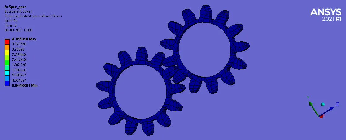
It is clear that the maximum equivalent stress is higher for cast bronze which is 316.68 MPa followed by grey cast iron and cast steel with values 316.00 MPa and 308.96 MPa respectively. The stress intensity is highest for cast steel with a value of 419.54 MPa followed by cast bronze and gray cast iron with values 418.89 MPa and 417.13 MPa respectively.
Errors encountered: When Isotropic Secant Coeffient of thermal expansion was empty for cast steel and cast bronze, error was displayed by generating the solution in the modeler.
To solve this problem, we deleted this property.
CONCLUSION:
To sum up it can be seen that cast bronze fails more quickly than other materials since it has more stress intensity and also has higher equivalent stress. The crack formation or failure for the same number of cycles is quicker in the case of cast bronze since it has higher stress intensity values. Hence, cast bronze is the least preferred material. Between gray cast iron and cast steel, gray cast iron will be preferred because the equivalent stress is higher for gray cast iron but the value of stress intensity is less. The machinability of gray cast iron is better than that of cast steel. Also, as discussed above the crack formation or failure for the same number of cycles is quicked for cast steel as compared to gray cast iron since the value of stress intensity is higher for cast steel.