Week 1- Mixing Tee
Mixing Tee
AIM:- To set up steady-state simulations to compare the mixing effectiveness when hot inlet temperature is 360C & cold inlet is at 190C.
Use the k-epsilon and k-omega SST model for the first case and based on your judgment use the more suitable model for further cases. Giving the reason for choosing a suitable model is compulsory.
- Case 1
- Short mixing tee with a hot inlet velocity of 3m/s.
- Momentum ratio of 2, 4.
- Case 2
- Long mixing tee with a hot inlet velocity of 3m/s.
- Momentum ratio of 2, 4.
Momentum ratio = velocity at cold inlet / velocity at hot inlet
In a table, compare the following values from the 2 cases.
- Cell count
- Average outlet temperature
- Number of iterations for convergence
T joint is a flow control device that is used for mixing different types of the flow stream which results in the final temperature which is than the mixed value of two different inlets
The most number of applications of Tee is seen in air conditioning system
STEPS:-
1. Select and drag Fluid Flow (Fluent)
- Select and drag Fluid Flow (Fluent) from toolbox and drag and past in project schematic window.
2 . Geometry preparation:-
- Select geometry and open > edit in SpaceClaim & select the geometry from the local file.
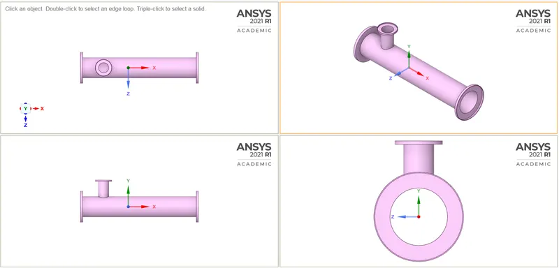
- Clame->Prepare->Volume extraction->Selecting edges->Click green tick.
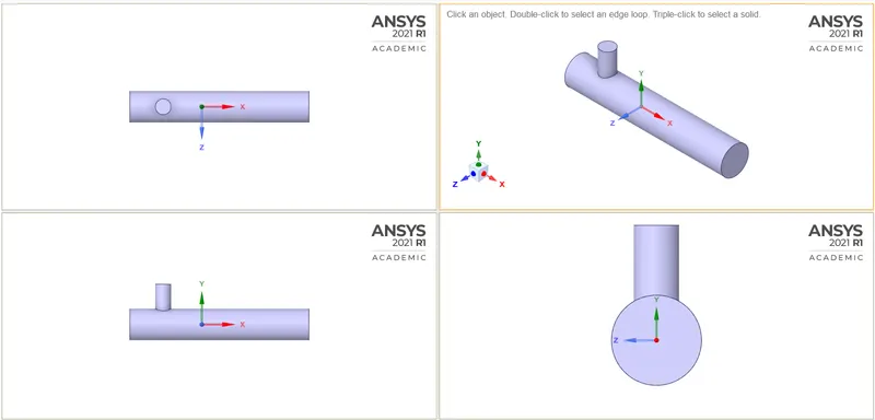
- Then in structure->mixing tee short->Unselect shell1->(right click) suppress for physics->close geometry
- Right-click Mesh update and select edit.
3. Meshing:-
- Open mesh->entity selection->Face selection and select the faces of geometry to be mentioned as a boundary
- Name Inlet X, inlet Y, outlet and Walls.
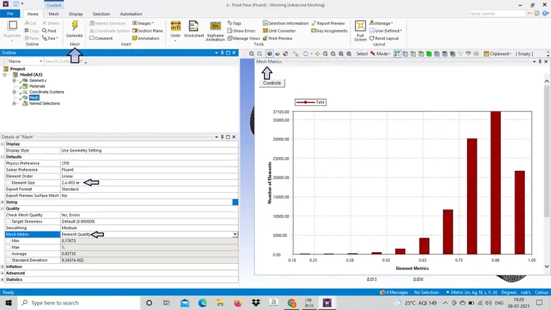
- Mesh-> Generate Mesh.
- Details of "mesh"->Defaults->Element size-> set to 0.002.
- Details of "mesh"->Quality->Mesh Metric-> set to Element quality.
- Close Mesh and update mesh and update setup in workbench
4. SETUP.
- Setup initial
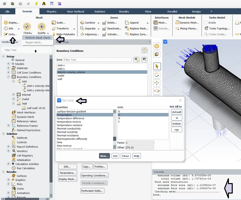
- Check->perform mesh check, we can see checking mesh................... Done that means the mesh is correct.
- Setting units, Unit->set unit->temprature->change to C from K.
- Setting physics for the flow.
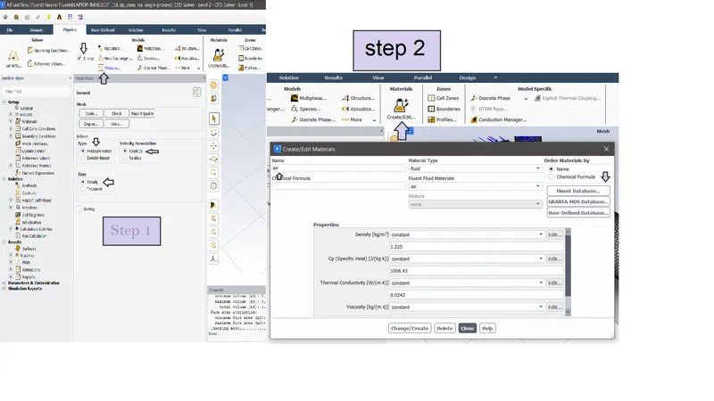
- Step 1-> tick Energy; Genral-> presssure based; velocity formulation ->absolute ;Time-> steady.
- Step 2-> Go to material ->set to Air
- Set Boundary conditions
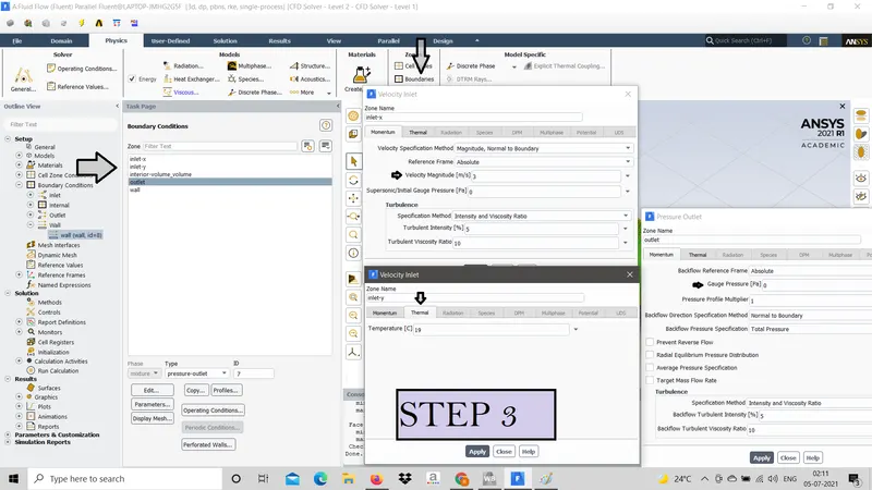
- Boundary-> Intel-x->Momentum->Velocity magnitude-> 3m/s. Thermal->Temprature(hot)->36.
- Inlet-y->Momentum->Velocity magnitude-> 6m/s. Thermal->Temprature(hot)->19.
- Outlet->Guage pressure->0.
- Report file and report plot.
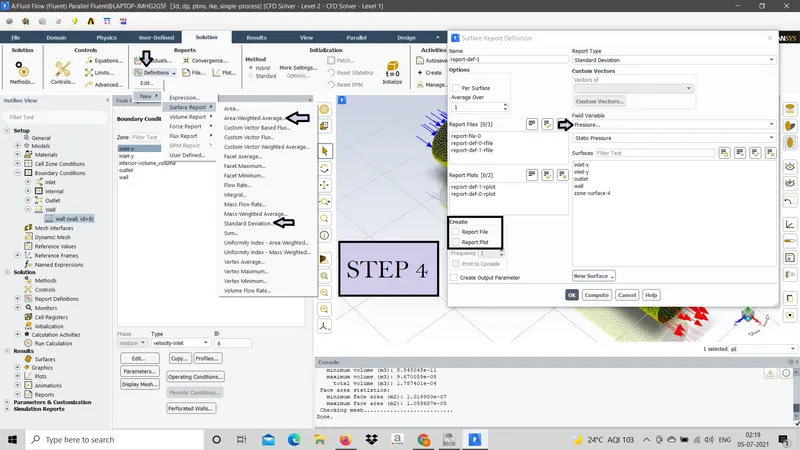
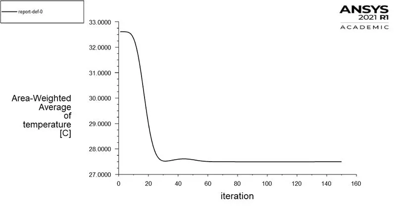
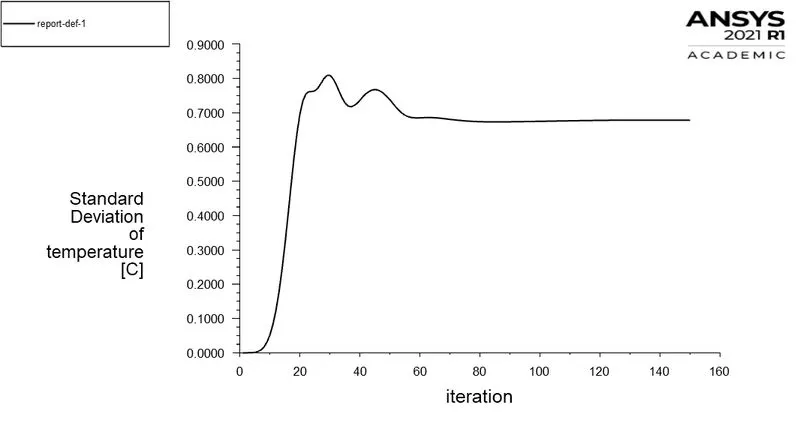
- Go to Solution, Definitions -> New -> surface report ->select area-weighted Average & Standard deviation.
- TICK report file & report plot; change field variable to Temprature-> Surface Outlet-> OK (for both).
- CALCULATE.
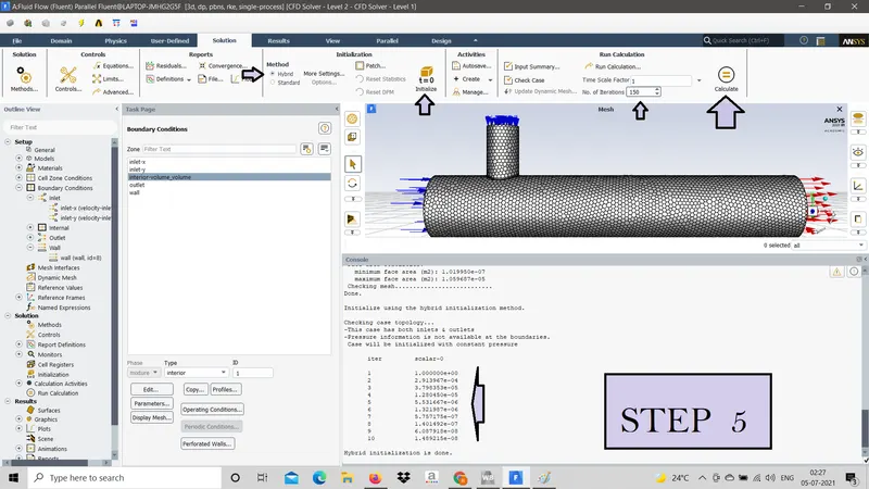
- In Solution -> Method ->tick Hybrid->Initialize. 10 iterations are perform
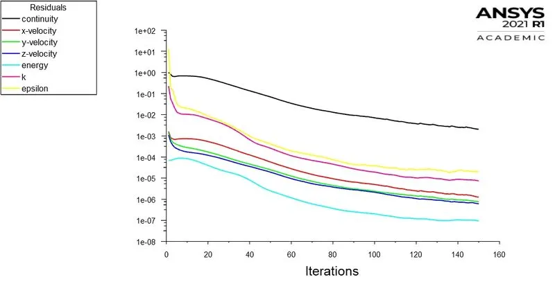
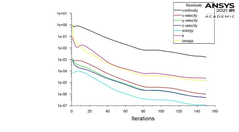
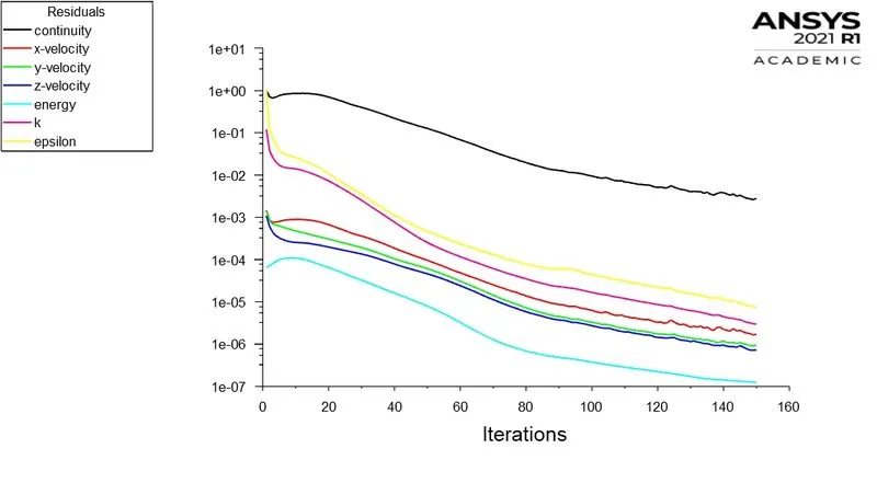
- No. of Iterations-> 150-> Calculate. And results are plotted as given below.
Which is more suitable k-epsilon and k-omega SST ?
K-epsilon model is the most common model used in CFD to simulate mean flow characteristics for Turbulent flow conditions. It is a two-equation model that gives a general description of Turbulent by means of two transport equations (PDEs). The original impetus for the K-epsilon model was to improve the mixing-length model, as well as to find an alternative to algebraically prescribing turbulent length scales in moderate to high complexity flows.
K-omega model is one of the most commonly used turbulence models. It is a two-equation model, which means, it includes two extra transport equations to represent the turbulent properties of the flow. This allows a two-equation model to account for historical effects like convection and diffusion of turbulent energy. The first transported variable is turbulent kinetic energy, . The second transported variable in this case is the specific dissipation, . It is the variable that determines the scale of the turbulence, whereas the first variable, , determines the energy in the turbulence
Relizable K- epsilon is used since it exhibits superior performance when flow involves rotation and boundary layers with adverse pressure gradients.
It is effective for predicting the flow behavior at a region away from the wall.
K-epsilon With momentum ratio 2:-
Scaled residuals:-
K-omega With momentum ratio 2:-
Scaled residuals:-
- CASES
Since , Momentum ratio = velocity at cold inlet/velocity at hot inlet
Therefore velocity at cold inlet=velocity at hot inlet* Momentum ratio.
| Geometry | Case no. | Inlet velocity | Momentum ratio | Inlet velocity of cold air |
| Short Tee | Case 1.1 | 3 m/s | 2 | 6 m/s |
| Short Tee | Case 1.2 | 3 m/s | 4 | 12 m/s |
| Long Tee | Case 2.1 | 3 m/s | 2 | 6 m/s |
| Long Tee | Case 2.2 | 3 m/s | 4 | 12 m/s |
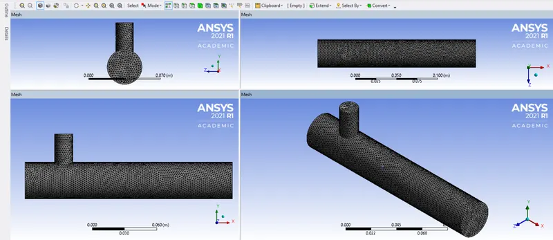
- MESHING IN SHORT TEE & LONG TEE
- SHORT TEE
- Mesh Size
Nodes 21288 Cells 105618 Faces 218315
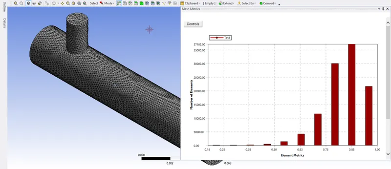
- Mesh Quality
| Name | Type | Min Orthogonal Quality | Max Aspect Ratio |
| volume_volume | Tet Cell | 0.2309382 | 15.735306 |
- Orthogonal Quality.
- TEE :-
- Mesh Size
-
Nodes 22341 Cells 140413 Faces 290341
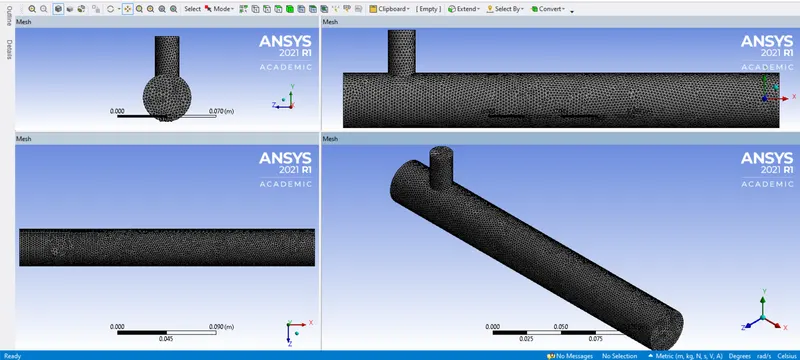
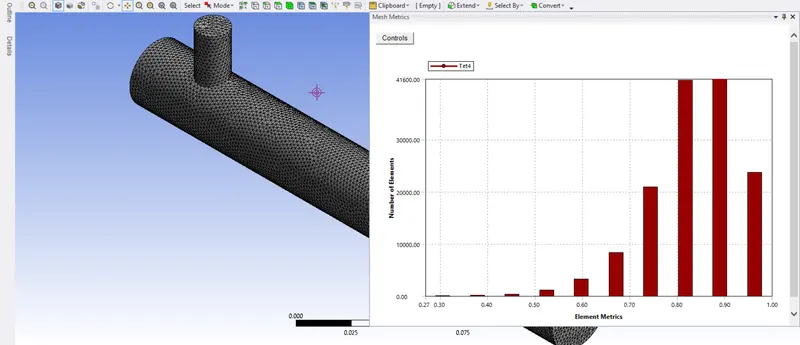
- Mesh Quality
| Name | Type | Min Orthogonal Quality | Max Aspect Ratio |
| volume_volume | Tet Cell | 0.26221179 | 12.843168 |
- Orthogonal Quality.
-
CASE 1.1
SHORT TEE
- Momentum ratio - 2
- Inlet velocity of hot air - 3m/s
- Inlet velocity of cold air - 6m/s
- INLET BOUNDARY CONDITION
| INLET-Y | INLET-X | |
| Velocity Specification Method | Magnitude, Normal to Boundary | Magnitude, Normal to Boundary |
| Reference Frame | Absolute | Absolute |
| Velocity Magnitude [m/s] | 6 | 3 |
| Supersonic/Initial Gauge Pressure [Pa] | 0 | 0 |
| Temperature [C] | 19 | 36 |
| Turbulent Specification Method | Intensity and Viscosity Ratio | Intensity and Viscosity Ratio |
| Turbulent Intensity [%] | 5 | 5 |
| Turbulent Viscosity Ratio | 10 | 10 |
- OUTLET BOUNDARY CONDITION
| OUTLET | |
| Backflow Reference Frame | Absolute |
| Gauge Pressure [Pa] | 0 |
| Pressure Profile Multiplier | 1 |
| Backflow Total Temperature [C] | 26.85 |
| Backflow Direction Specification Method | Normal to Boundary |
| Turbulent Specification Method | Intensity and Viscosity Ratio |
| Backflow Turbulent Intensity [%] | 5 |
| Backflow Turbulent Viscosity Ratio | 10 |
| Backflow Pressure Specification | Total pressure |
- Plots
- Residuals
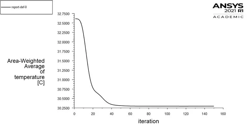
- Area-Weighted Average of temperature
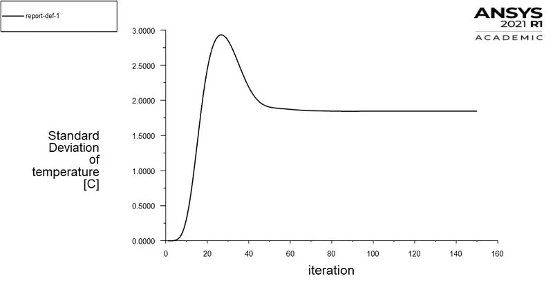
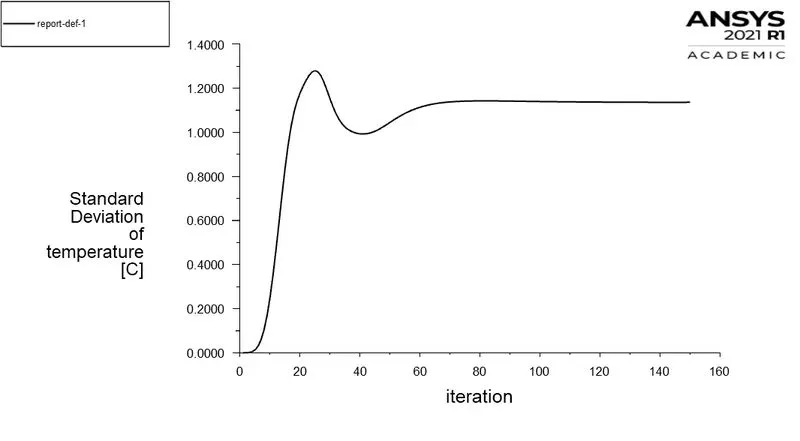
- Standard Deviation of temperature
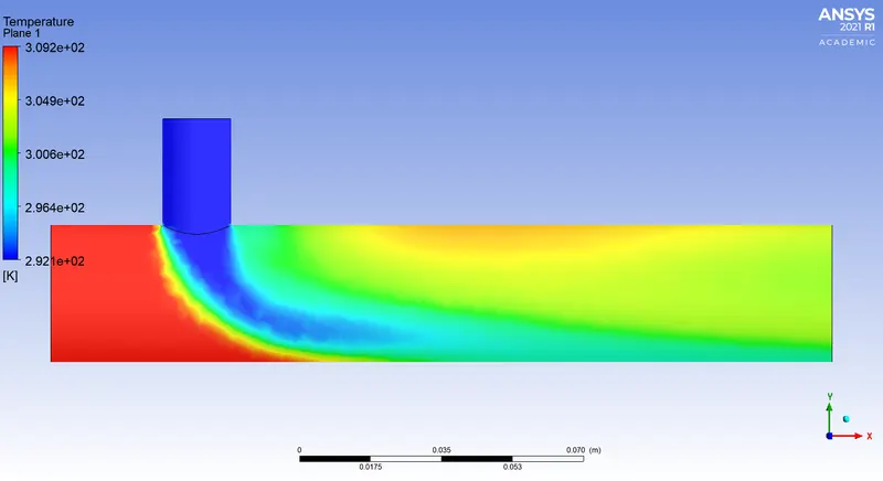
RESULTS
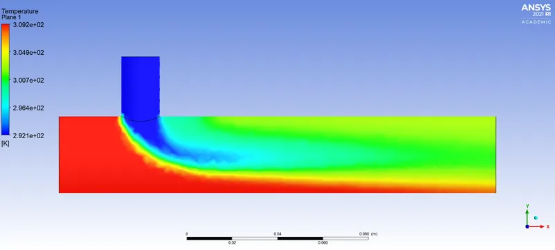
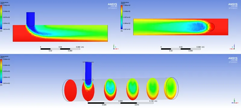
CASE 1.2
SHORT TEE
- Momentum ratio - 2
- Inlet velocity of hot air - 3m/s
- Inlet velocity of cold air - 6m/s
- INLET BOUNDARY CONDITION
| INLET-Y | INLET-X | |
| Velocity Specification Method | Magnitude, Normal to Boundary | Magnitude, Normal to Boundary |
| Reference Frame | Absolute | Absolute |
| Velocity Magnitude [m/s] | 12 | 3 |
| Supersonic/Initial Gauge Pressure [Pa] | 0 | 0 |
| Temperature [C] | 19 | 36 |
| Turbulent Specification Method | Intensity and Viscosity Ratio | Intensity and Viscosity Ratio |
| Turbulent Intensity [%] | 5 | 5 |
| Turbulent Viscosity Ratio | 10 | 10 |
- OUTLET BOUNDARY CONDITION
| OUTLET | |
| Backflow Reference Frame | Absolute |
| Gauge Pressure [Pa] | 0 |
| Pressure Profile Multiplier | 1 |
| Backflow Total Temperature [C] | 26.85 |
| Backflow Direction Specification Method | Normal to Boundary |
| Turbulent Specification Method | Intensity and Viscosity Ratio |
| Backflow Turbulent Intensity [%] | 5 |
| Backflow Turbulent Viscosity Ratio | 10 |
| Backflow Pressure Specification | Total pressure |
- Plots
- Residuals
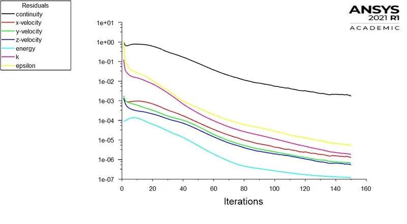
- Area-Weighted Average of temperature
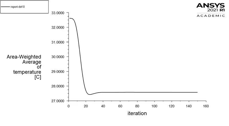
- Standard Deviation of temperature
RESULTS
CASE 2.1
LONG TEE
- Momentum ratio - 2
- Inlet velocity of hot air - 3m/s
- Inlet velocity of cold air - 6m/s
- INLET BOUNDARY CONDITION
| INLET-Y | INLET-X | |
| Velocity Specification Method | Magnitude, Normal to Boundary | Magnitude, Normal to Boundary |
| Reference Frame | Absolute | Absolute |
| Velocity Magnitude [m/s] | 6 | 3 |
| Supersonic/Initial Gauge Pressure [Pa] | 0 | 0 |
| Temperature [C] | 19 | 36 |
| Turbulent Specification Method | Intensity and Viscosity Ratio | Intensity and Viscosity Ratio |
| Turbulent Intensity [%] | 5 | 5 |
| Turbulent Viscosity Ratio | 10 | 10 |
- OUTLET BOUNDARY CONDITION
| OUTLET | |
| Backflow Reference Frame | Absolute |
| Gauge Pressure [Pa] | 0 |
| Pressure Profile Multiplier | 1 |
| Backflow Total Temperature [C] | 26.85 |
| Backflow Direction Specification Method | Normal to Boundary |
| Turbulent Specification Method | Intensity and Viscosity Ratio |
| Backflow Turbulent Intensity [%] | 5 |
| Backflow Turbulent Viscosity Ratio | 10 |
| Backflow Pressure Specification | Total pressure |
- Plots
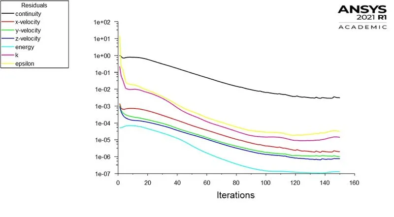
- Residuals
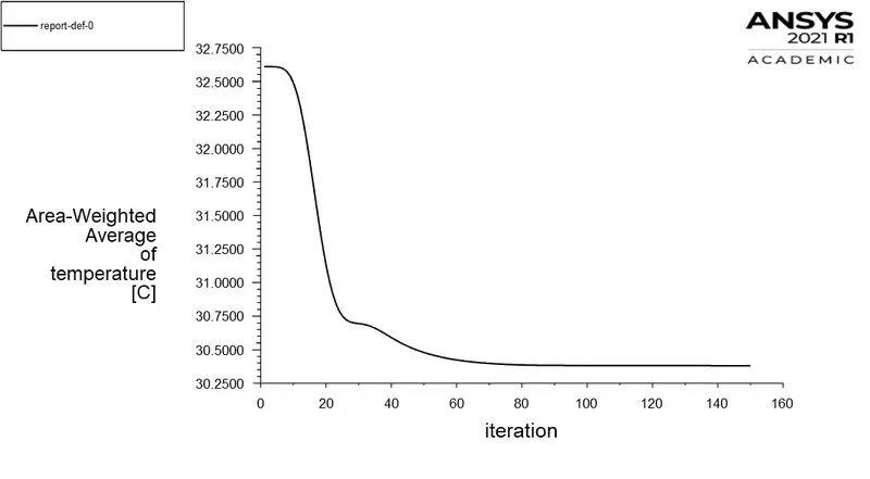
- Area-Weighted Average of temperature
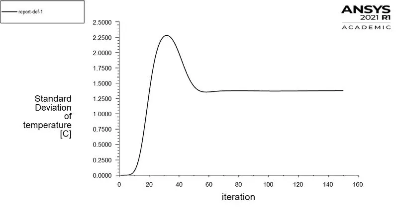
- Standard Deviation of temperature
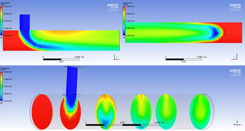
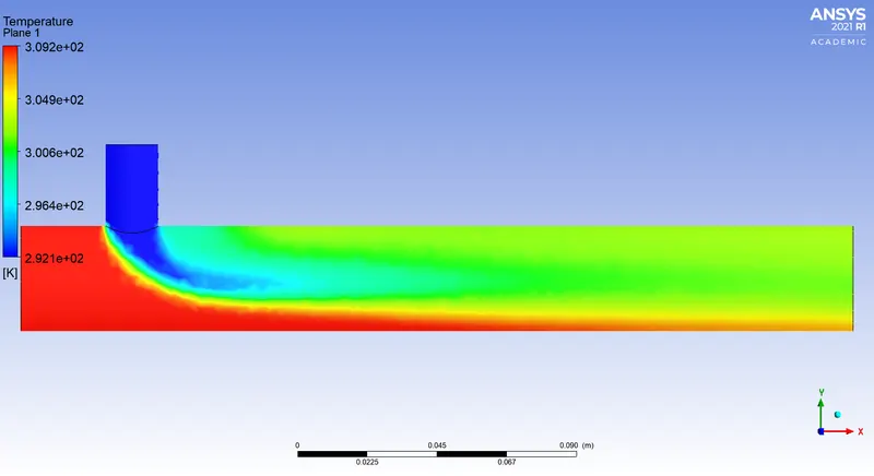
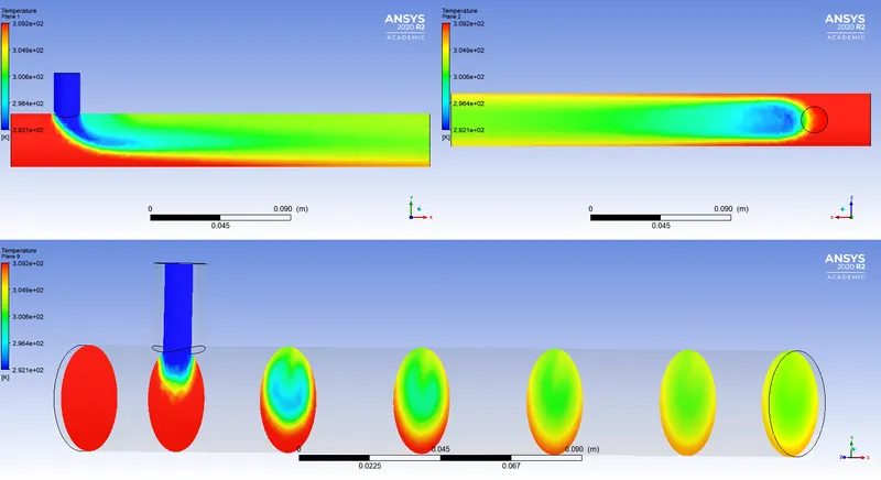
RESULTS
CASE 2.2
LONG TEE
- Momentum ratio - 2
- Inlet velocity of hot air - 3m/s
- Inlet velocity of cold air - 6m/s
- INLET BOUNDARY CONDITION
| INLET-Y | INLET-X | |
| Velocity Specification Method | Magnitude, Normal to Boundary | Magnitude, Normal to Boundary |
| Reference Frame | Absolute | Absolute |
| Velocity Magnitude [m/s] | 12 | 3 |
| Supersonic/Initial Gauge Pressure [Pa] | 0 | 0 |
| Temperature [C] | 19 | 36 |
| Turbulent Specification Method | Intensity and Viscosity Ratio | Intensity and Viscosity Ratio |
| Turbulent Intensity [%] | 5 | 5 |
| Turbulent Viscosity Ratio | 10 | 10 |
- OUTLET BOUNDARY CONDITION
| OUTLET | |
| Backflow Reference Frame | Absolute |
| Gauge Pressure [Pa] | 0 |
| Pressure Profile Multiplier | 1 |
| Backflow Total Temperature [C] | 26.85 |
| Backflow Direction Specification Method | Normal to Boundary |
| Turbulent Specification Method | Intensity and Viscosity Ratio |
| Backflow Turbulent Intensity [%] | 5 |
| Backflow Turbulent Viscosity Ratio | 10 |
| Backflow Pressure Specification | Total pressure |
- Plots
- Residuals
- Area-Weighted Average of temperature
- Standard Deviation of temperature
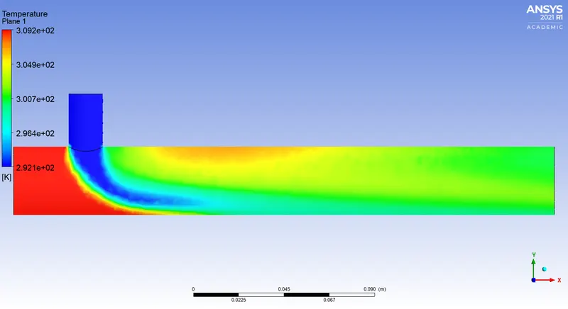
RESULTS
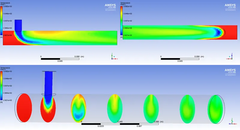
CONCLUSION:-
- In this project we simulate turbulant flow model which is far from the boundary, therefore the K-epsilon model is used.
- As K-epsilon model preditcs the flow virtually far from the boundaries, and K-omega preditcs near the boundary.
- As the number of element increases the mesh quality improves and simulation becomes more accurate.
- To obtain better mixing at outlet momentum ratio of higher values gives better results, i.e. greater the velocity at cold inlet better the mixing.
- As the length of pipe increases it gives better mixing at the outlet. Therefore long pipe with higher velocity inlet of cold air will give better mixing then others as compared