Week 1- Mixing Tee
AIM : To perform analysis of the Mixing Tee for different verisons, to study mixing of fluid and the heat exchange between the fluid.
OBJECTIVES :
- Setting up the model Geometry of the Mixing Tee with the given Cad file for mixing tee.
- Create optimal meshing for the model.
- Setup the model for the analysis, from the given data as follows -
Hot inlet temperature is `36^@C` & the Cold inlet is at `19^@C`
Case 1
Case 2
Short mixing tee with a hot inlet velocity of 3m/s.
Momentum ratio of 2, 4.
Long mixing tee with a hot inlet velocity of 3m/s.
Momentum ratio of 2, 4.
- Run the simulation and Post Process the results.
INTRODUCTION :
A Mixing Tee is a flow control device that mixes two different fluid streams into one combined fluid stream. It has two inlets and one outlet, with one inlet located along the X-axis and the other along the Y-axis, and the outlet located along the X-axis. Mixing Tees utilize a specifically engineered internal geometry to efficiently mix the two fluid streams.
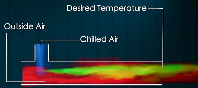
( Source: Skill-Lync Youtube )
Mixing Tees are widely used in various industries, such as the petrochemical and HVAC industries, where two fluid streams with different physical and/or chemical properties need to be mixed together. For example, hot air flowing in the main pipe can be mixed with cold air flowing through a tee to achieve a desired temperature at the outlet.
The effectiveness of mixing in a Mixing Tee can be influenced by various factors, such as the length of the pipe and the momentum ratio of velocity for mixing of air.
The momentum ratio is defined as the ratio of velocity at the cold inlet to the velocity at the hot inlet.
STEPS / PROCEDURE :
For Both Cases -
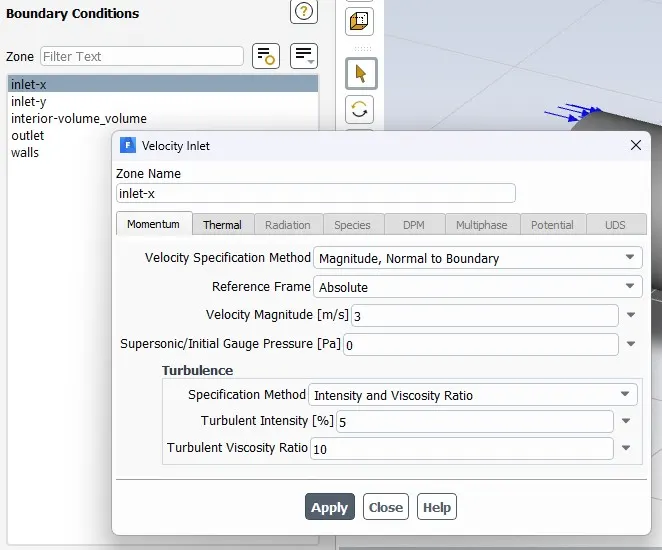
Inlet Velocity X-Direction = 3 m/s
For Momentum Ratio 2, Inlet Velocity Y-Direction = 6 m/s
For Momentum Ratio 4, Inlet Velocity Y-Direction = 12 m/s
CASE 1 : Short Mixing Tee
1.1 Geometry
The Following is the given geometry, opened via spaceclaim in workbench -
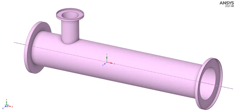
Doing volume extraction inside the mixing tee, and cleanup the geometry as the solid region is not need since we are only analyzing fluid flow.
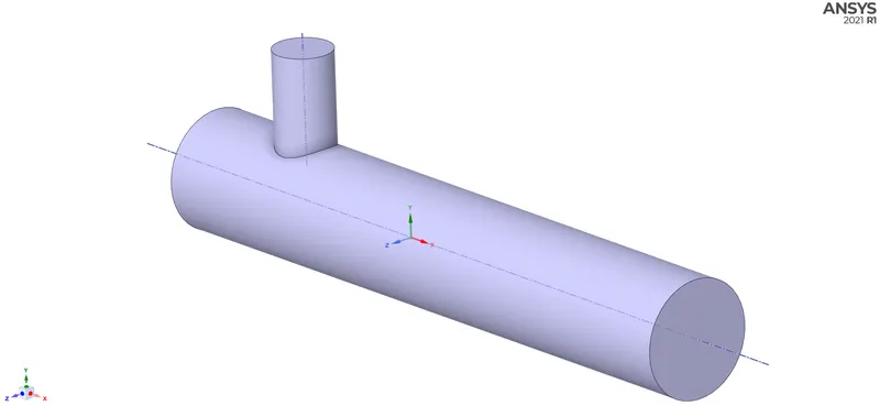
1.2) Meshing
After doing Geometry preparation, we gone open the geometry in Ansys Mesher via workbench -
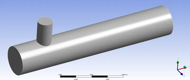
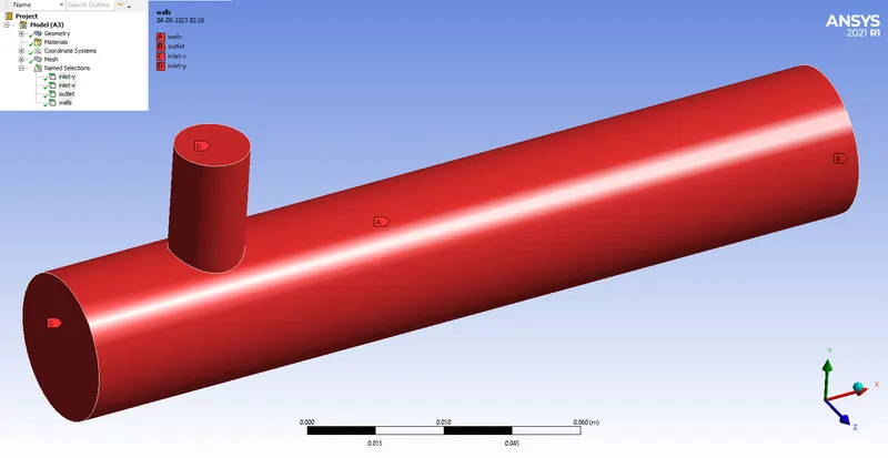
Creating Named Selections for respective faces -
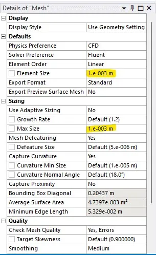
Mesh Settings -
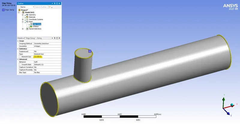
Assigning Edge sizing
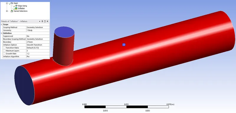
Assigning Inflation
Mesh Quality Verification-
Following is the surface mesh of the Case Setup -
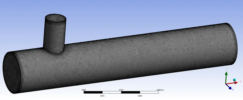
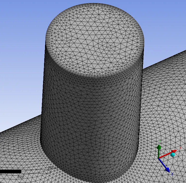
Following is the visualising the mesh inside -
- Cut plane of XY plane at 50% of the cabinet in Z-direction from origin (Front Plane)
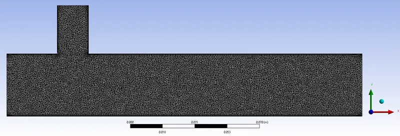
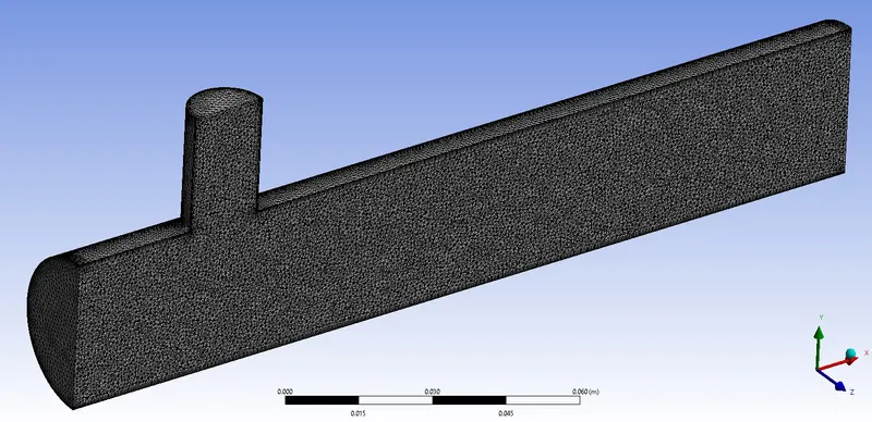
- At outlet face in X-direction
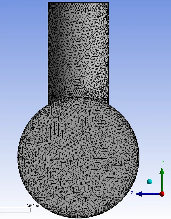
Mesh Quality Parameters -
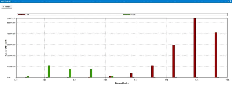
We can the mesh quality is very satisfied. 90% of the mesh cell are lying on good quality range.
1.3) Solver Settings -
Closing the Mesher & opening the Fluent Solver from the workbench
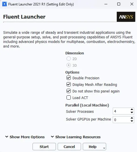
Checking the the Double precision option and selecting no. of parallel process.
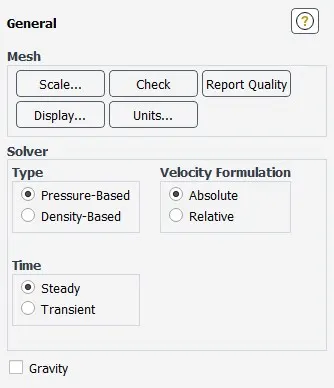
Setting solver settings and initialization values.
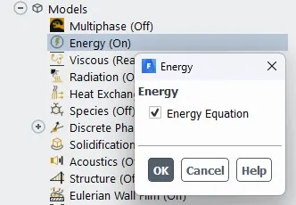
Currently we solving it in pressure based solver because there's negligible change in density, and turning on the Energy Equation since we are analysing the heat Transfer.
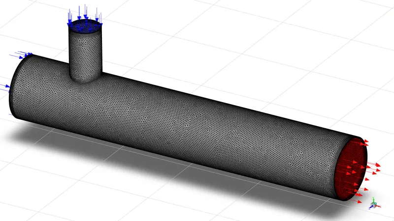
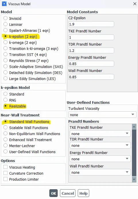
Selecting the turbulence model and its settings.
Now assigning the boundary conditions inlets, outlet, and walls.
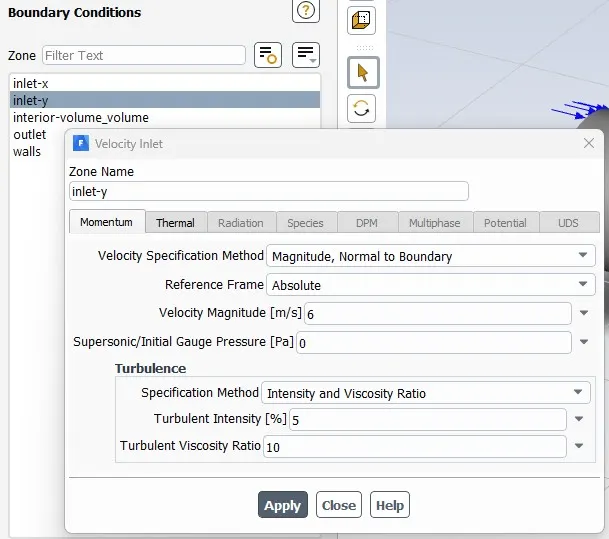
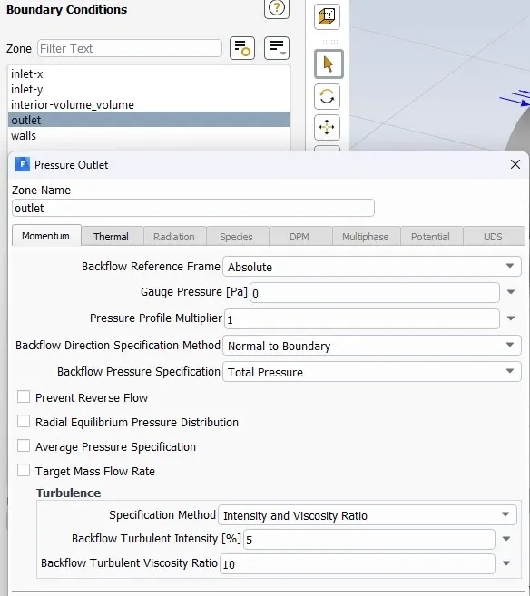
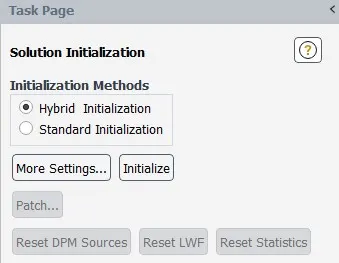
Setting Inilization, here we are using Hybrid Initialization.
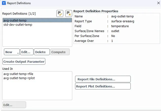
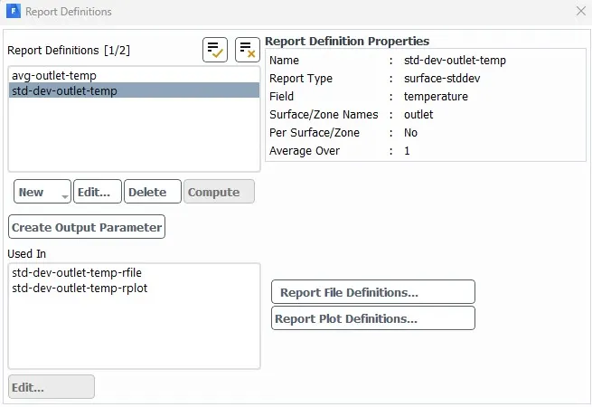
Creating Solution reports.
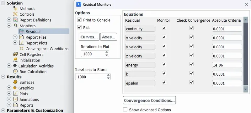
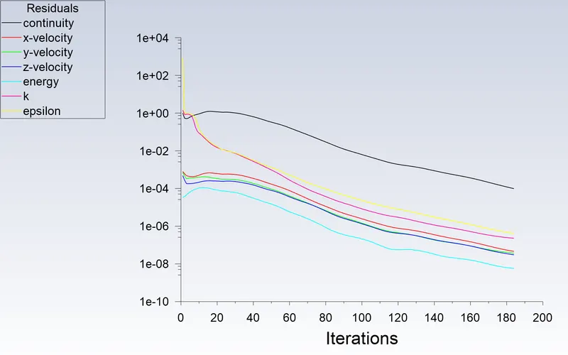
The convergence criteria of Flow is set to 0.0001 and energy is set to 1e-6, turbulent kinetic energy to 0.0001.
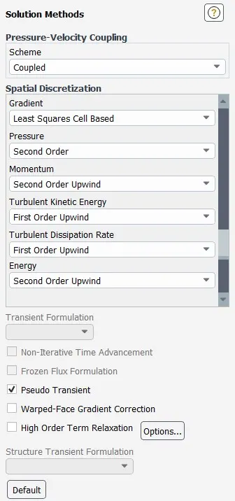
Keeping the Solution method & discretization schemes to Default. Turning on Psuedo transient option inorder for better accuracy.
In the Calculation panel, setting the number of iterations to 300.
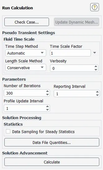
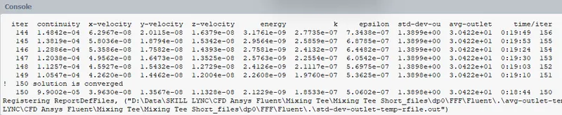
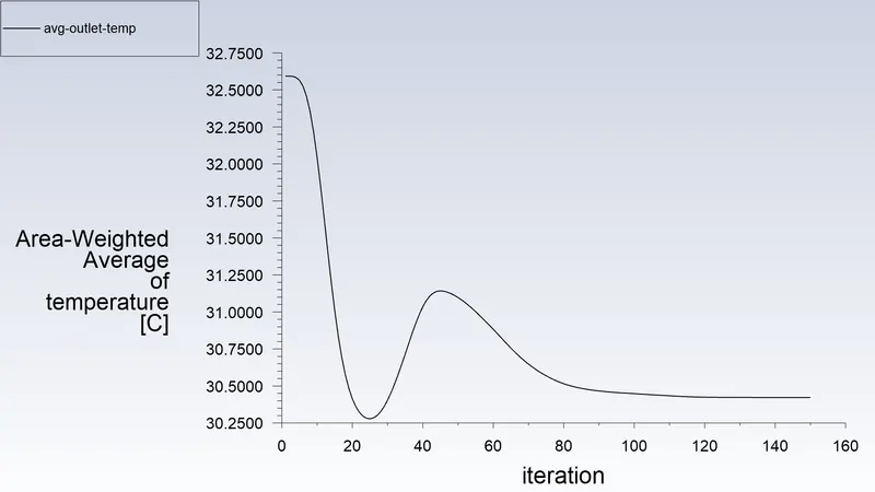
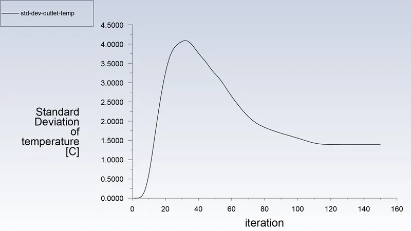
After Running the calculation the simulation gets converged at 150th iteration.
For the Momentum ratio of 4 i.e at 12 m/s
Using the geometry and of the previous analysis and doing the analysis for 12m/s
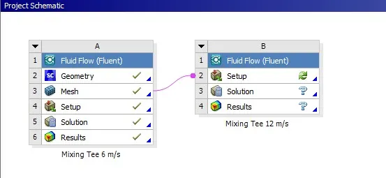
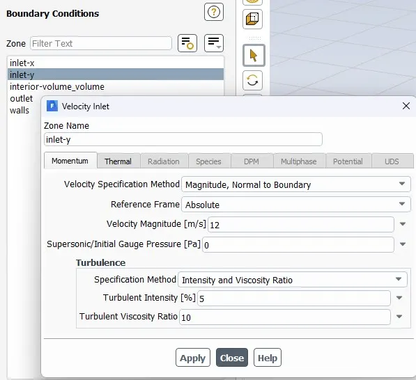
keeping all other settings are same as previous only the IntletY temp is 12m/s
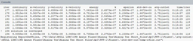
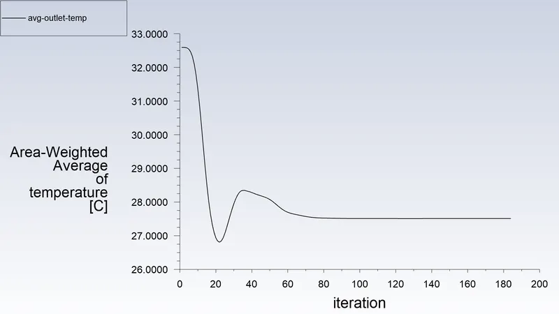
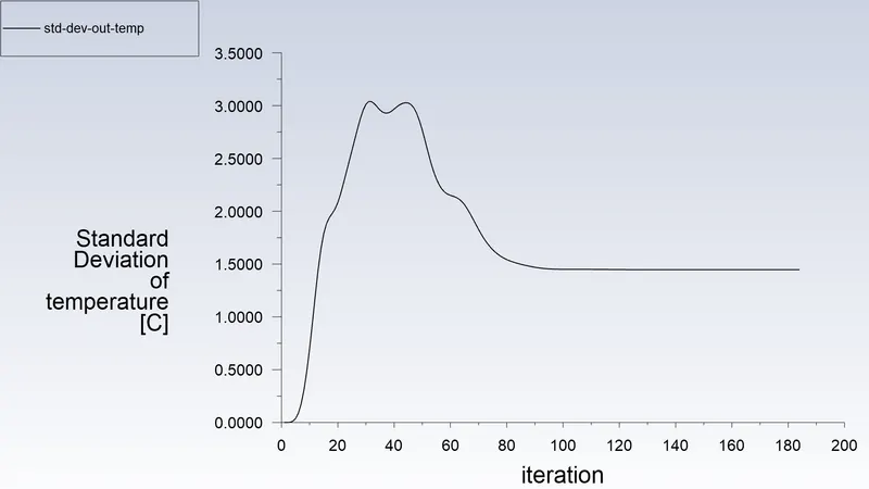
After Running the calculation the simulation gets converged at 184th iteration.
CASE 2 : Long Mixing Tee
2.1 Geometry
The Following is the given geometry, opened via spaceclaim in workbench -
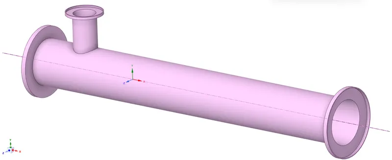
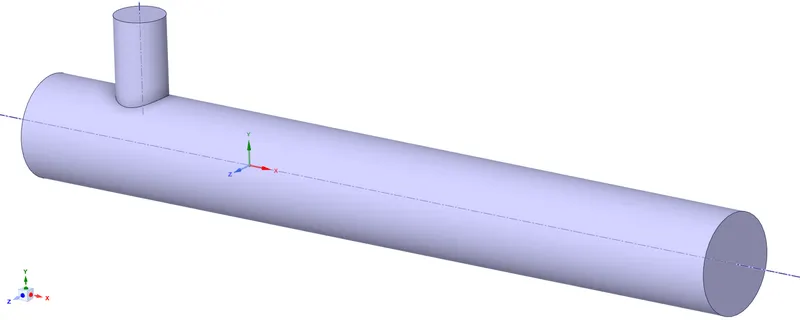
Doing volume extraction inside the mixing tee, and cleanup the geometry as the solid region is not need since we are only analyzing fluid flow.
2.2) Meshing
After doing Geometry preparation, we gone open the geometry in Ansys Mesher via workbench.
Creating Named Selections for respective faces.
Mesh Settings -
Assigning Edge sizing and Inflation with same parameter values as short tee case.
Mesh Quality Verification-
Following is the surface mesh of the Case Setup -
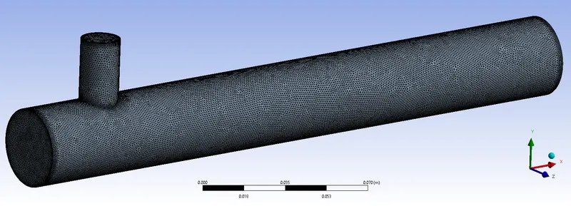
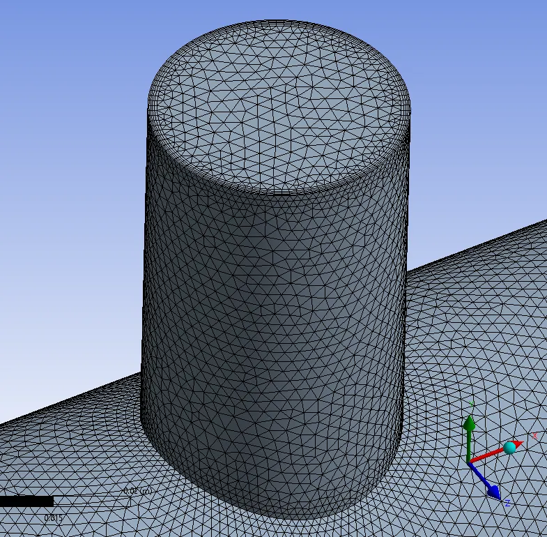
Following is the visualising the mesh inside -
- Cut plane of XY plane at 50% of the cabinet in Z-direction from origin (Front Plane)
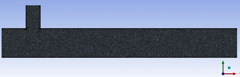
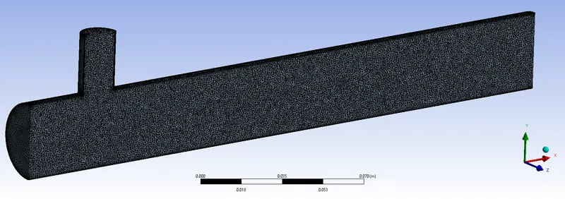
- At outlet face in X-direction
Mesh Quality Parameters -
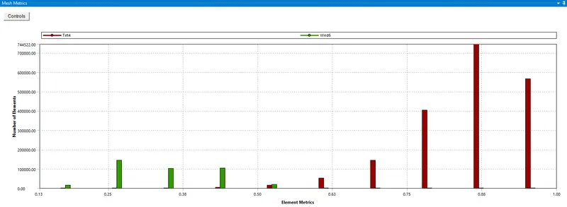
We can the mesh quality is very satisfied. 90% of the mesh cell are lying on good quality range.
2.3) Solver Settings -
Closing the Mesher & opening the Fluent Solver from the workbench
Setting solver settings and initialization values.
The convergence criteria of Flow is set to 0.0001 and energy is set to 1e-6, turbulent kinetic energy to 0.0001.
Keeping the Solution method & discretization schemes to Default.
In the Calculation panel, setting the number of iterations to 300.
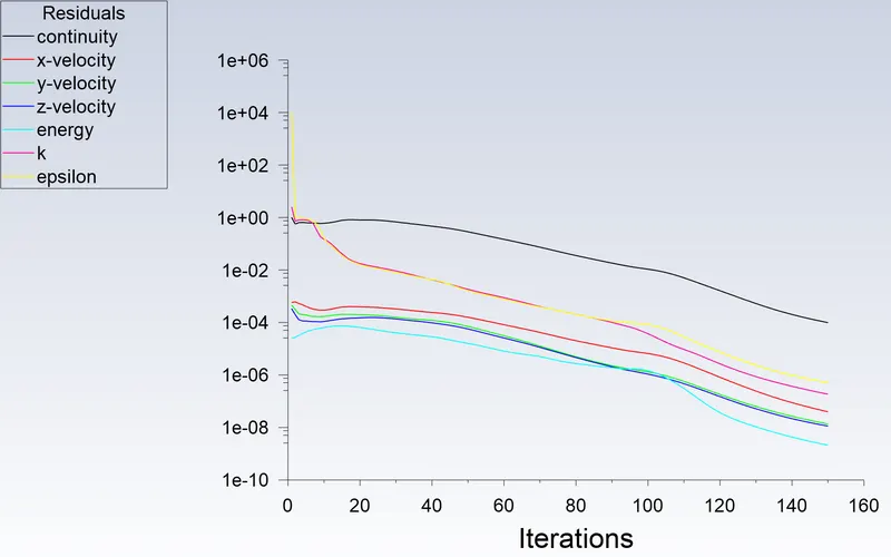
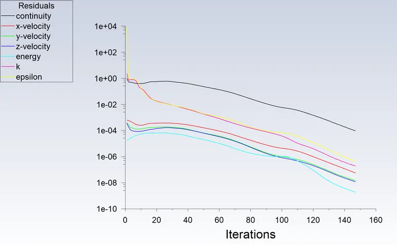
After Running the calculation the simulation gets converged at 147th iteration.

For the Momentum ratio of 4 i.e at 12 m/s
Using the geometry and of the previous analysis and doing the analysis for 12m/s
keeping all other settings are same as previous only the IntletY temp is 12m/s
After Running the calculation the simulation gets converged at 169th iteration.

POST PROCESSING :
Outputs
1. For Short Mixing tee at Momentum Ratio of 2 -
Residuals and Solution Monitor Plot -
Contour Plots -
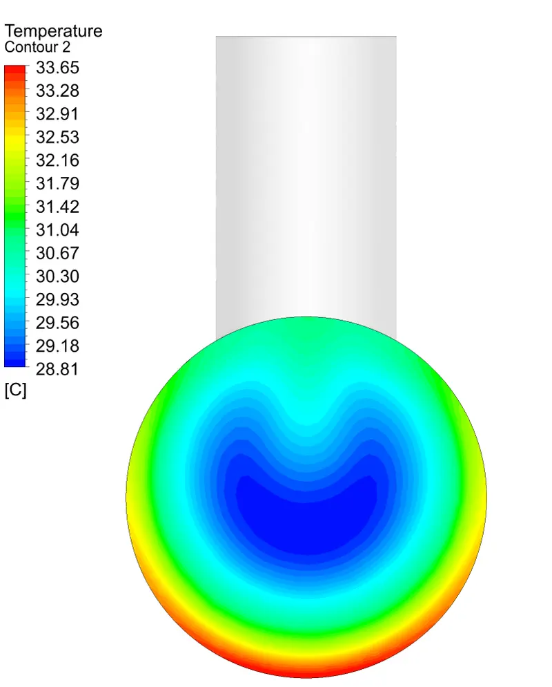
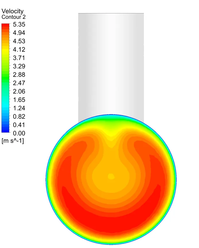
Along X Direction at Outlet Face -
Along Z Direction at 50% -
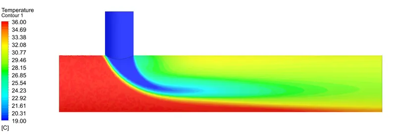
Temperature Contour -
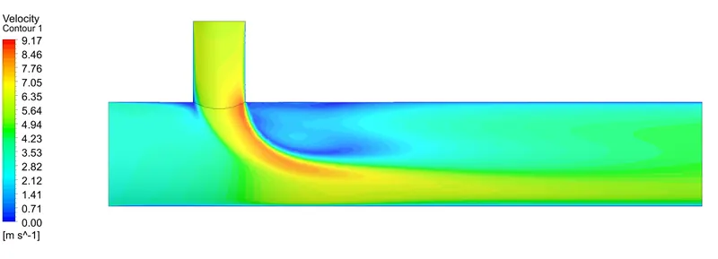
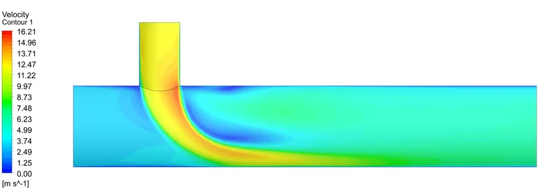
Velocity Contour -
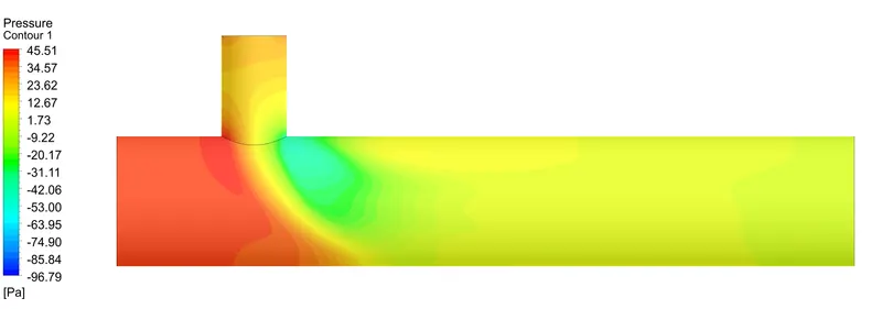
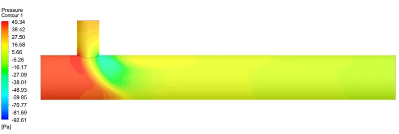
Pressure Contour -
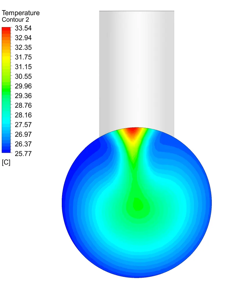
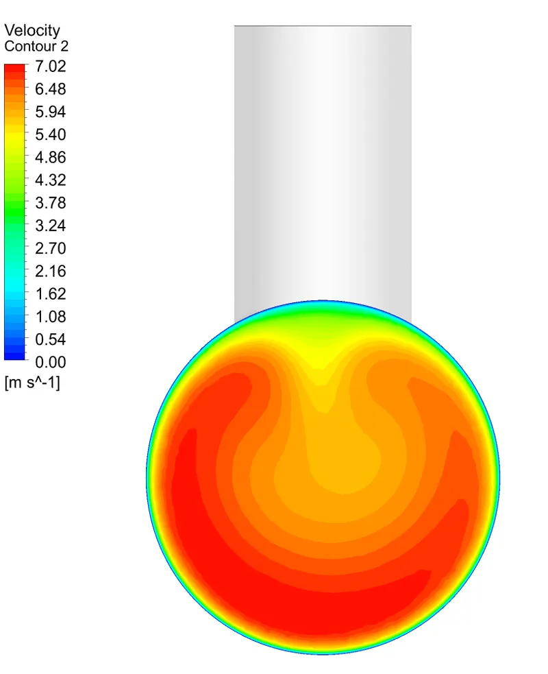
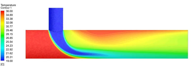
2. For Short Mixing tee at Momentum Ratio of 4 -
Residuals and Solution Monitor Plot -
Contour Plots -
Along X Direction at Outlet Face -
Along Z Direction at 50% -
Temperature Contour -
Velocity Contour -
Pressure Contour -
3. For Long Mixing tee at Momentum Ratio of 2 -
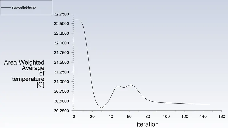
Residuals and Solution Monitor Plot -
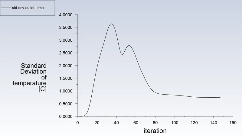
Contour Plots -
Along X Direction at Outlet Face -
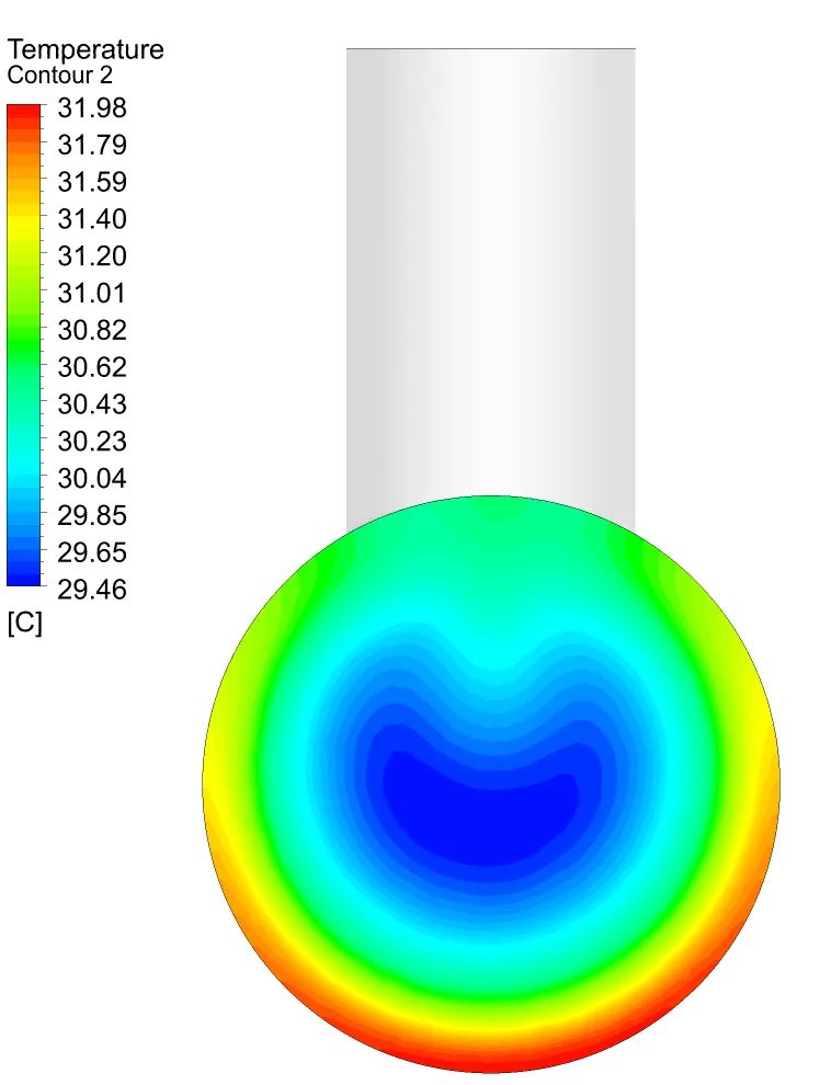

Along Z Direction at 50% -
Temperature Contour -
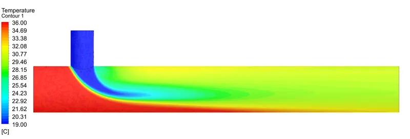
Velocity Contour -
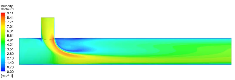
Pressure Contour -
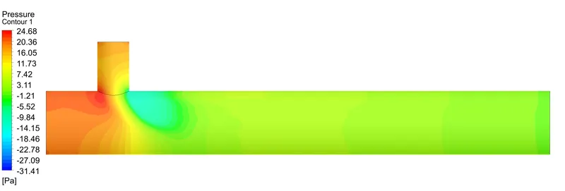
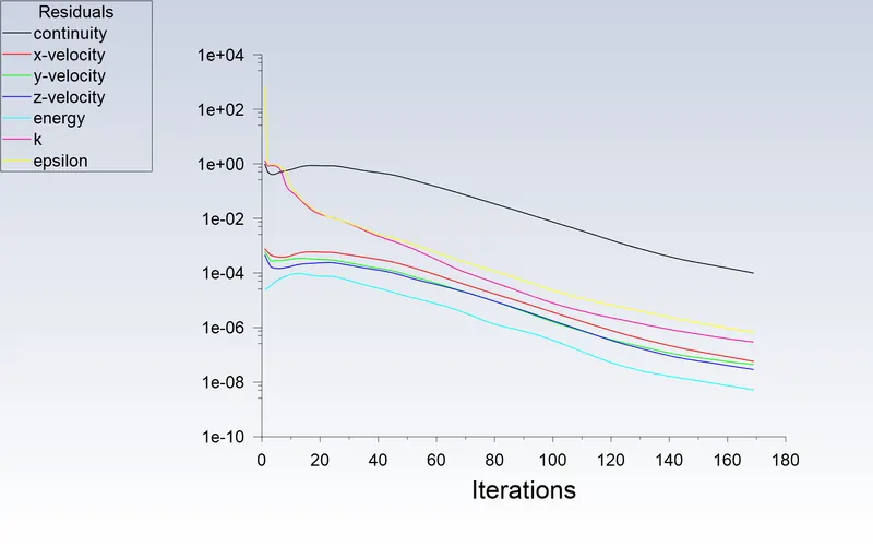
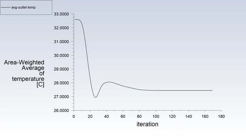
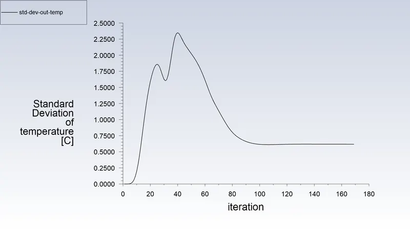
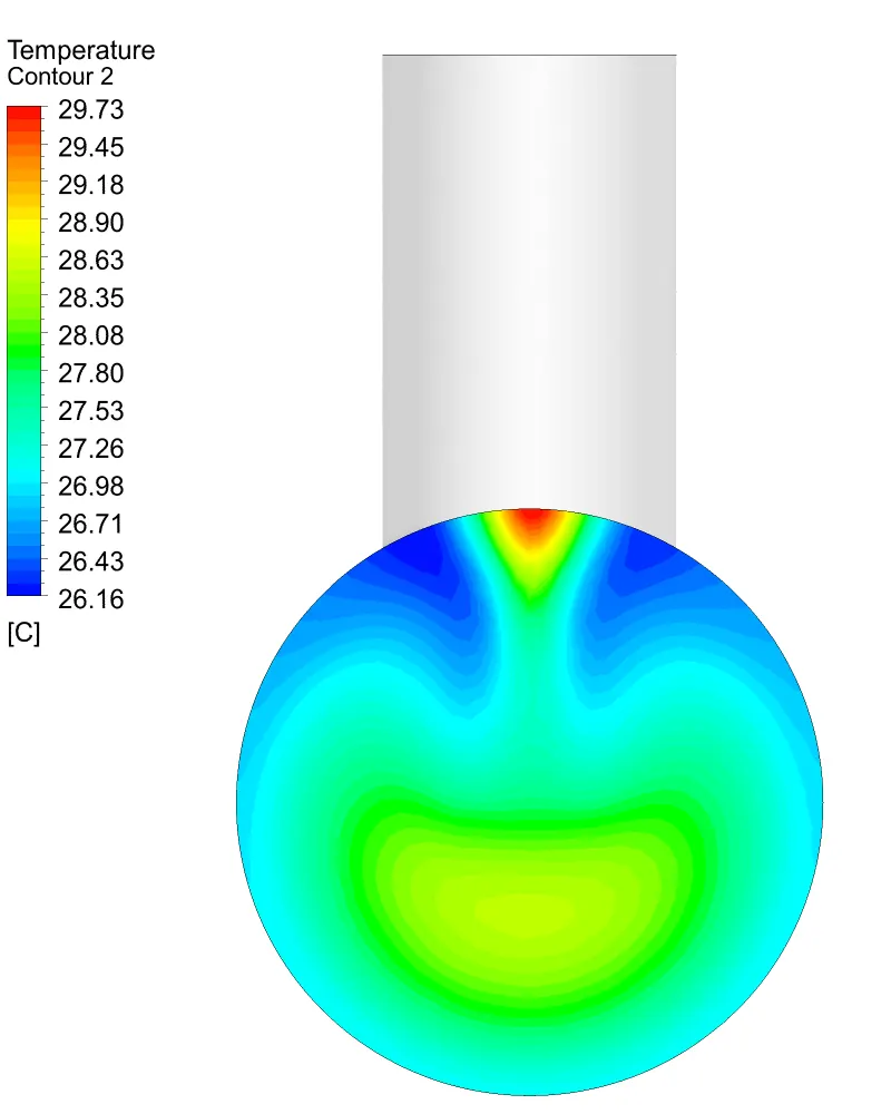
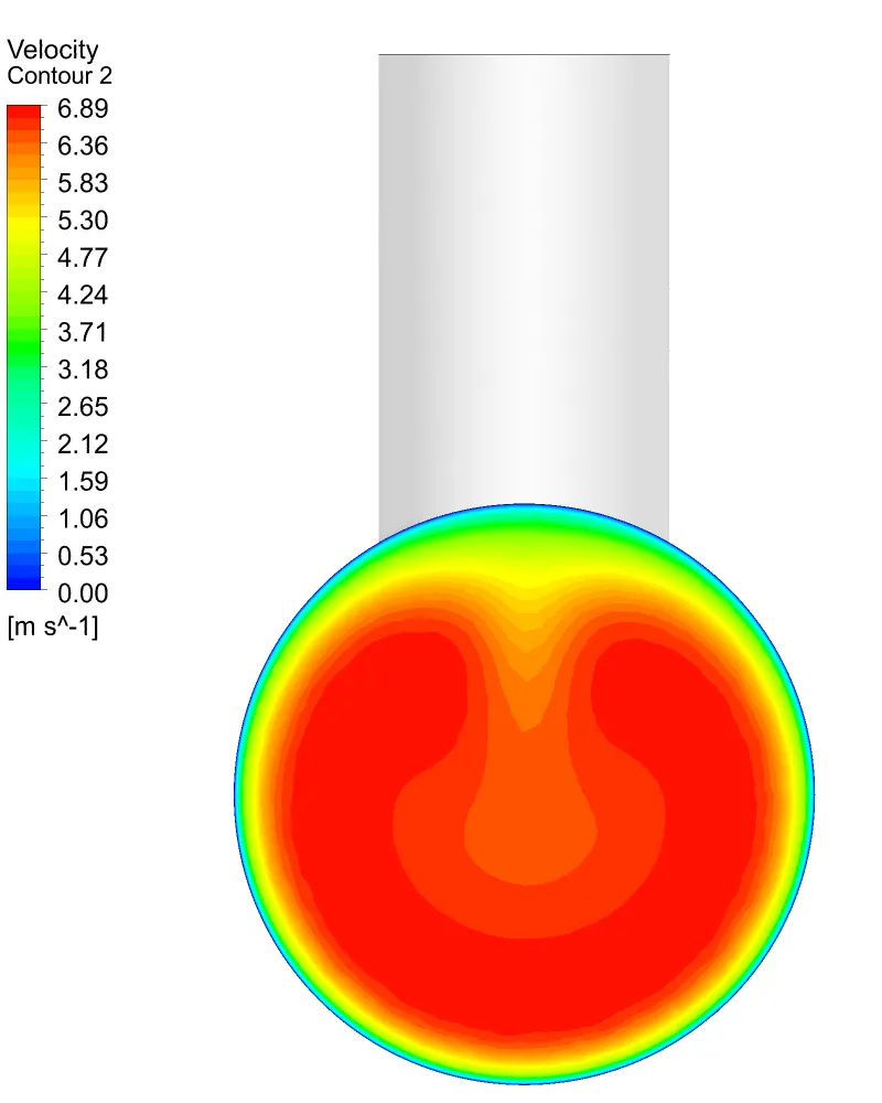
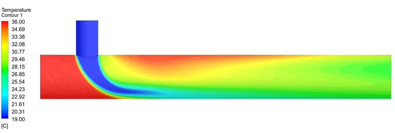
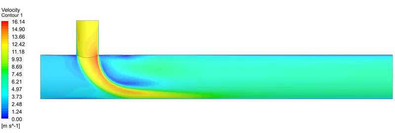
4. For Long Mixing tee at Momentum Ratio of 4 -
Residuals and Solution Monitor Plot -
Contour Plots -
Along X Direction at Outlet Face -
Along Z Direction at 50% -
Temperature Contour -
Velocity Contour -
Pressure Contour -
RESULTS :
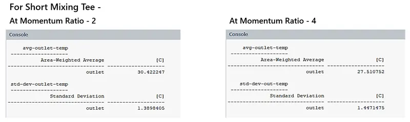
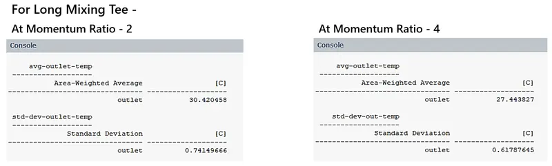
The Following are the summary report of results of the simulation, -
CONCLUSION :
We have successfully performed the Thermal analysis for the Mixing tee.
The appropriate Edge Sizing and Inflation were used for optimum Meshing.
The solver was set up using suitable settings to incorporate the physical phenomena.
We were able to generate required contours for temperature, speed, & pressure.
The following conclusions can be drawn based on the simulation results after running -
- We can see the temperatures attained are realistic and all the residuals are less than 10e-3 and the Solution got converged.
- The Higher Momentum Ratio the More the Turbulence and therefore there is more mixing.
- The Longer Mixing Tee provides More region and time for mixing along the path before exit.
For further, inorder to check accuracy we can run simulation by more mesh refinement along the walls and using k-omega SST turbulence model.
REFERENCE :
- Th. Frank, C. Lifante, H.-M. Prasser, F. Menter,'Simulation of turbulent and thermal mixing in T-junctions using URANS and
scale-resolving turbulence models in ANSYS CFX'; https://doi.org/10.1016/j.nucengdes.2009.11.008