Week 1:- Introduction to BiW and Fixtures Challenge
1. What is BIW?
- In the Automotive Industry BIW (Body in White) is the common terminology used to mention the car sheet metal welded structure (body shell).
- In today's situation, automotive BIW is made of steel (various steel grade material -DP, DD, HDP etc.) as well as made of aluminium alloy (e.g. AUDI A8)
- Sub-assemblies like Under body, Body side Left Hand Side/ Right Hand Side, Front End, Roof etc. gets welded together by various metal joining process e.g. resistance spot welding, Laser welding, MIG welding to make welded metal shell (Without Door, Trunk-lid / Tailgate) , Fender, Bonnet Center) called Body in White.
- Automotive car shell made before painting is called Body in White.
- BIW joinery decides the exterior and interior look of any car.
- All the Interior Parts(Commonly used in Automotive) e.g. Dashboard, Trim (Door Trim, Pillar Trims, Roof liner, Seats are mounted on the BIW shell with the help of various brackets or nuts mounted on the BIW.
- Exterior (Commonly used term in car industry) components e.g. Front Bumper, Rear Bumper, Fender LH/RH, Side Mirrors are mounted on the BIW shell with the help of various brackets or mounting systems.
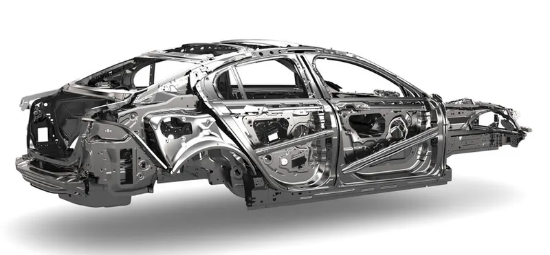
- The term derives from manufacturing practices before steel unibody monocoques — when automobile bodies were made by outside firms on a separate chassis with an engine, suspension, and bumpers attached.The manufacturers built or purchased wooden bodies (with thin, non-structural metal sheets on the outside) to bolt onto the frame. The bodies were painted white prior to the final color.
- A folk etymology for "body in white" is the appearance of a car body after it is dipped into a white bath of primer (undercoat paint)— despite the primer's actual gray color.BIW could also refer to when car bodywork would be made of timber - all timber products, furniture, etc., are considered to be "in the white" when at the stage of raw timber before finishing or varnishing.
- That stage in automotive design or automobile manufacturing in which the car body sheet metal components are assembled by any means like welding, riveting or bolting, etc. is called BIW (Body In White). Moving parts such as Door, Hood, Trunk Lid, Front Fender, and the components (chassis, motor) and trim (windshields, seats, upholstery, electronics, etc.) are added in a later stage.
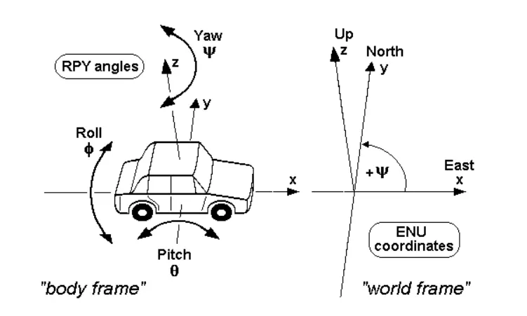
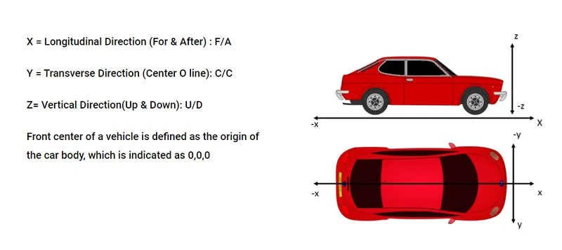
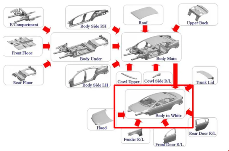
define its parts
1. under body
2. upper body
3. main body
4. clousures
1. under body
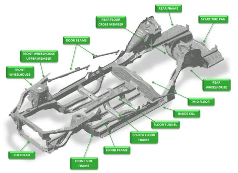
The Bulkhead is positioned at the front of the automobile. Radiators, condensers, head lights, etc., are mounted at the automobile assembly plants. Front bulkheads are designed with a closed cross-section structure to enhance the rigidity of the whole automobile, while considering the design of the automobile.
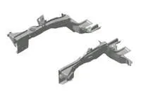
The Front Wheelhouse is constructed with the dome-shaped wheelhouse that shrouds the tires and damper space that holds the suspension dampers. The damper space and its surrounding are required to be strong enough to withstand the forces transmitted from the road.
The Front Wheelhouse Upper Member is welded to the Front Wheelhouse Component. It is instrumental in the body structure to more evenly distribute frontal crash energy throughout the front of the vehicle for occupant protection.
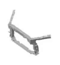
The Front Side Frame is positioned from the front bumper to the front of the cabin and it cradles the engine from both sides. While carrying the engine, which is the largest and heaviest component of the automobile, it also enhances the strength and rigidity of the entire automobile. It is designed to absorb and disperse the shock backward, and drop the engine downward so it will not be pushed into the cabin, or the frame itself will crumple on the impact.
To achieve both the strength and the ability to collapse within one product, steels with different specifications are welded together with laser welding. By using a tailored, blank material machined as a single steel stock, we have realized multiple forms while enhancing the productivity.
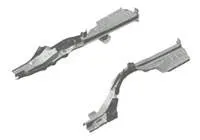
The Rear Frame is the frame positioned from the rear seat to the rear bumper. Strength and rigidity are the key components to protect the cabin and fuel tank in the case of a collision. The Rear Frame should maintain rigidity while expanding the distance between the frames to give the occupant comfort and a variety of seat layouts. It has a complex and rugged shape, requiring high forming technology.
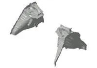
The Rear Wheelhouse is welded to the Rear Frame Component on the outboard side of the vehicle. The shape of the part houses the rear tires and strut assembly. The main stamping of this comp is usually made of a mild steel material to allow for sufficient stretch when drawing the part during the stamping process. Depending on the vehicle, the comp will support the pillar, parcel shelf, seat belt harnesses, cargo hooks, and electronic and sound system units.
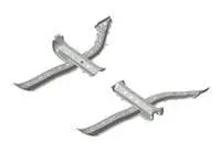
The Floor Frame Component runs longitudinal from the front Side Frame and ties in to the Center Floor Frame and Inside Sill. This component, along with the Inside Sill, aids in improving the torsional and bending rigidity which then aids in reducing the noise, vibration, and harshness (NVH) of the vehicle. Ultimately, the floor panel will weld to this component.
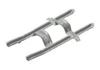
The Center Floor Frame runs longitudinal from the Front Side Frame to the Mid Floor Cross Member. This component, along with the Inside Sill, aids in improving the torsional and bending rigidity which then aids in reducing the noise, vibration, and harshness (NVH) of the vehicle. The U-shaped members allow room for the drive train and exhaust system routing. Ultimately, the floor panel will weld to this component.
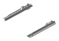
The Inside Sill runs longitudinal from the Front Side Frame to the Rear Frame on the outboard sides of the vehicle. The Inside Sill provides bending and rigidity improvement but is also instrumental in the support of the Side Pillars and redirecting frontal impact energy for collision safety.
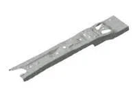
The Floor Tunnel runs longitudinal from the Front Side Frame to the Mid Floor Cross Member in the center of the vehicle. It welds directly to the Mid Floor Cross Member. The shape of the part allows for the center console to be attached during assembly. It also provides an area for the drive train and exhaust systems to be routed to the rear of the vehicle in the cavity below the part.
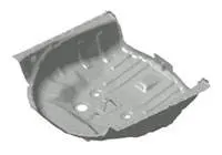
The Spare Tire Pan is located in the rear of the vehicle directly below the trunk cargo area. The main purpose of this part is to house the spare tire. It is usually made of a mild steel material for better stretch because of the deep draw shape of the main stamping.
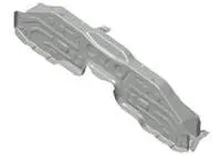
The Mid Floor Comp is a cross body comp which welds to the Inside Sill and Rear Frame components. This component also aids in improving the torsional and bending rigidity which aids in reducing the noise, vibration, and harshness (NVH) of the vehicle. Ultimately, the floor panel will weld to this component.
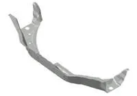
The Rear Floor Cross Member is a cross body part which welds directly to the Rear Frame component. This component aids in improving the torsional and bending rigidity which aids in reducing the noise, vibration, and harshness (NVH) of the vehicle. The mating shape of this component helps support the Spare Tire Pan component.
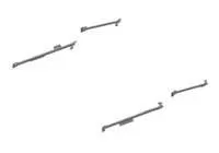
The Door Beams are installed, parallel to the ground, inside each door. They protect the occupants by instantaneously and effectively absorbing the energy from impact during a front and side collision. KTH uses a unique quenching process that tremendously enhances the strength, while at the same time makes the Door Beam very lightweight.
2. upper body
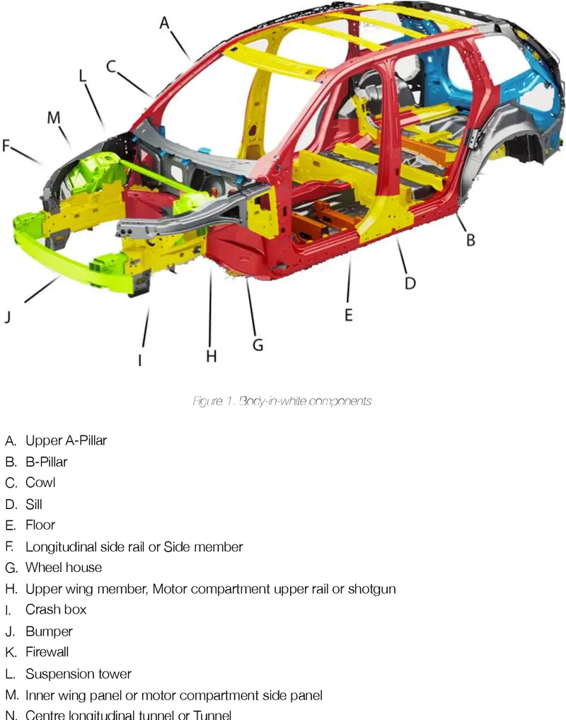
An upper body section of a car body includes right and left front pillars, each front pillar being comprised of an outer pillar panel and an inner pillar panel secured to each other and being provided with a pillar reinforcement panel disposed along the outer pillar panel. Brackets, through which a door is hinged, are secured to gussets disposed inside the outer pillar panel.
3. main body
- To support the vehicle's mechanical components and body
- To deal with static and dynamic loads, without undue deflection or distortion.
- These include:
-
- Weight of the body, passengers, and cargo loads.
- Vertical and torsional twisting transmitted by going over uneven surfaces.
- Transverse lateral forces caused by road conditions, side wind, and steering the vehicle.
- Torque from the engine and transmission.
- Longitudinal tensile forces from starting and acceleration, as well as compression from braking.
- Sudden impacts from collisions.
-
Types of frame according to their construction:
- Ladder-type frame
- X-Type frame
- Offset frame
- Offset with cross member frame
- Perimeter Frame
4. closures
- Automotive closures are a non-structural part of the vehicle that are hinged to the body frames, such as doors, to allow entry and exit from the vehicle. Automotive closures are a critical part of the vehicle, as they contribute to vehicle safety and add functional value. Automotive closures have witnessed a significant amount of development, in terms of design, weight, and features, for the last few years.
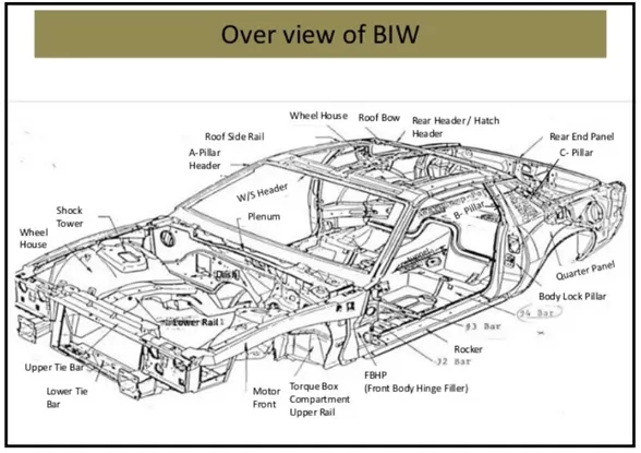
2. What do you understand by BIW nomenclature
nomenclature is basically choosing
of names for things BIW have no. of parts in it. All parts have
differenent names.
- As the Automotive industry is spread worldwide.
very nation has its own language. So the
same part of the
BIW/ have different names in region
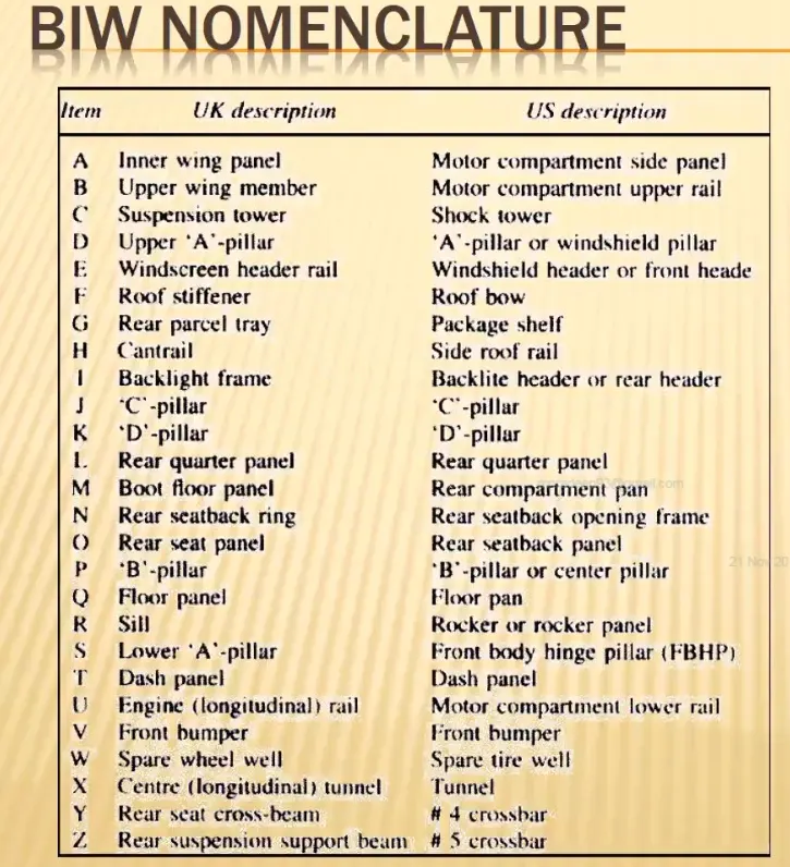
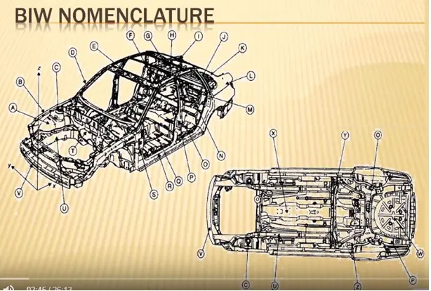
- For example, The one component of the BIW is called suspension tower in Uk & the same component is called shock tower in US.
3. What is fixture & its types
A fixture is a device which holds and locates a workpiece during an inspection or for a manufacturing operation. The fixture does not guide the tool.
In construction, the fixture comprises a different standard or specially designed work holding the device, which is clamped on the machine able to hold the work in the position. The tools are set at the required positions on the work by using gauges or by manual adjustment.
types of fixture
- Turning fixtures.
- Milling fixtures.
- Broaching fixtures.
- Grinding fixtures.
- Boring fixtures.
- Indexing fixtures.
- Tapping fixtures.
- Duplex fixtures.
- Welding fixtures.
- Assembly fixtures.
Turning fixtures
It is quite easy-to-hold regular workpieces on lathes in standard job holding devices like chucks and collects, between the centre and on mandrels or faceplates. But irregularly shaped components offer a lot of difficulties in holding them correctly.
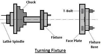
Simple odd shaped jobs can be held in chuck also, say by proper adjustment of jaws in a four-jaw chuck or by using shaped soft jaws. However, workpieces having complicated shaped have to be necessarily held in position with the help of turning fixtures. These fixtures are normally mounted on the nose of the machine spindle or on a faceplate and the workpieces held them.
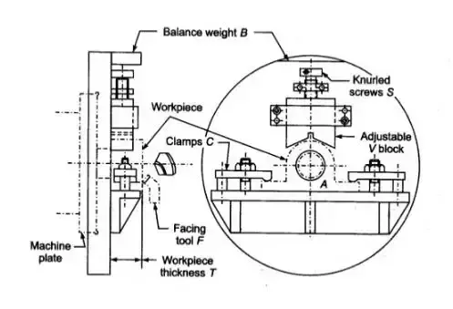
whenever necessary, the fixture may have to be provided with a counterweight or balance the unbalance fixture. These fixtures should be carefully designed, to be rigid enough, with minimum overhang should grip the workpieces very firmly, should not carry any dangerous projections for the machine operator or tool or both and should be able to provide proper support to him to thin and weak sections of the workpieces during the operation.
Milling fixtures
These fixtures are used on milling for carrying out different milling operations on workpieces. The fixture is properly located on the table of the machine and secured in position by means of bolts and nuts.
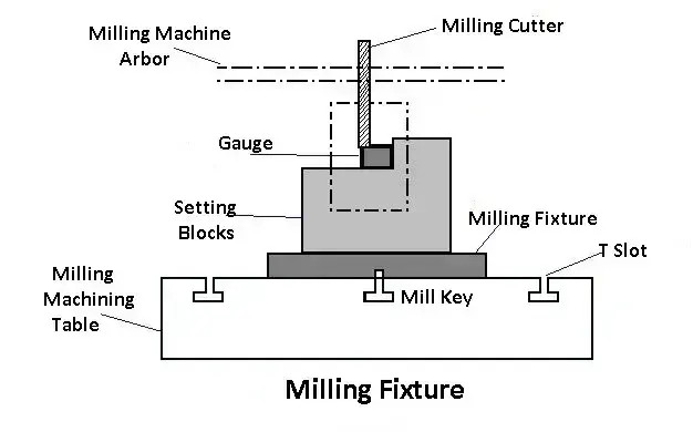
The table is shifted and set in the proper position, in relation to the cutter. The workpieces are located no the base of the fixture and clamped before starting the operation.
Since the cutting forces involved are quite high, and also intermittent, the clamping elements. Proper locating of the fixture on the machine table is usually achieved with the help of two tenons provided under the fixture base. These tenons enter a T-slot of the table to provide the required location. The fixture base can then be secured to the table by means of T-bolts and nuts.
Broaching Fixtures
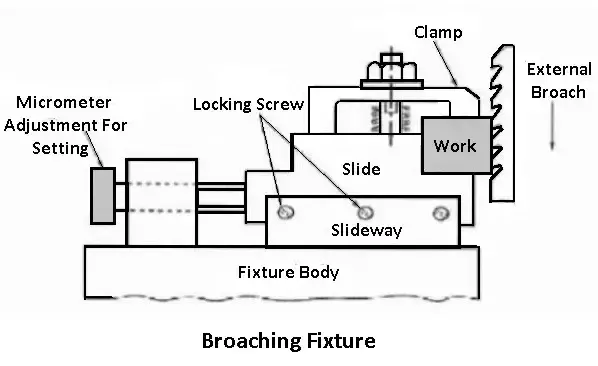
These fixtures are used on different types of broaching machines to locate, hold, and support the workpieces during the operations, such as keyway broaching operations, such as keyway broaching, hole broaching, etc. The use of a clamping plate as a fixture for internal pull-type hole broaching.
Grinding Fixture
Several different forms of fixtures are used in grinding machines to locate, hold, and support the workpieces during the operations. These fixtures may be the standard work-holding devices, such as chucks, mandrels, chuck with shaped jaws, magnetic chucks, etc.
For example; a vertical surface grinder with a rotary table will normally have a rotary fixture secured to its table. Similarly, a plain or string fixture may be provided on a surface grinder with the reciprocating table. A drill grinding attachment is a glaring example of a standard fixture used for grinding of drill geometry.
Whatever be the types of fixture designed for grinding operation, it should have provisions for supply and exit of coolant, mounting of wheel dressers and should be properly balanced, if it is a rotating fixture.
Boring Fixture
The operation can be performed in one of the following two ways:
- By keeping the boring bar (tool) stationary and feeding the touting workpiece on to the bar.
- By keeping the workpiece stationary and feeding the rotating boring bar into the work.
Accordingly, therefore, the boring fixture is made in two common designs.
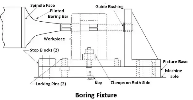
One of these incorporates the principle of a drilling jig, and in this, the boring bar (tool) is guided through a pilot bush. such fixture is also often referred to as boring jigs. the other design facilitates holding of the workpiece incorrect position, relative to the boring bar.
Although this fixture incorporates almost all the common principles of jig and fixture design, their construction need not be as sturdy as that of the milling fixtures, because they never have to bear as heavy cutting loads as involved in milling fixtures, because they never have to bear as heavy cutting loads as involved in milling operations.
Indexing Fixture
Several components need machining on the different surface such that their machined surface surfaces or forms are evenly spaced.
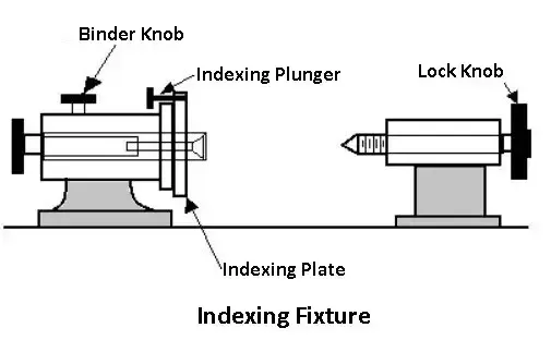
Such components are required to be indexed equally as many as the number of surfaces to be machined. Obviously, the holding devices (jigs or fixtures) used are made to carry a suitable indexing mechanism. A fixture carrying such a device is known as an indexing fixture.
Tapping Fixture
Tapping fixture is specially designed to position and firmly secure identical workpieces for cutting internal threads in drilled holes in them. Odd shaped and unbalanced components will always need the use of such fixtures, especially when the tapping operation is to be carried out repeatedly on a mass scale on such components.
Duplex Fixtures
It is the name given to the fixture which holds two similar components simultaneously and facilitates simultaneously machining of these components at two separate stations. While one workpiece is machined at one station.
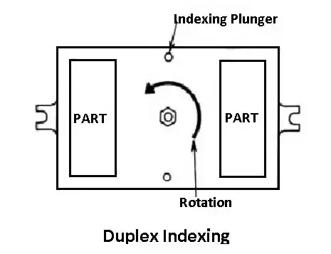
Both the operations according to the requirement may be similar or different. Once machining at both the stations is over, the fixture is indexed through 180 degrees so that the first component is shifted to the second station for the second operation and the finished component to the first station.
The finished component is then uploaded here, replaced by a fresh component and the first operation performed on it. The cycle goes on repeating, which enables mass production of components at a fairly high speed.
Welding Fixtures
Welding fixtures are carefully designed to hold and support the various components to be welded in proper locations and prevent distortions in welded structures. For this, the locating element need to be careful, clamping has to be light but firm, placement of clamping elements has to be clear of the welding area. The fixture has to be quite stable and rigid to withstand the welding stresses.
In many cases, a preferably and commonly used practice is to first tack weld the structure by holding it in welding jig and then transfer it to a holding fixture for full welding. This helps in reducing the chances of distortion considerably and the fixture is subjected to lesser stresses.
Assembly Fixture
The function of these fixtures is to hold different components together in their proper relative position at the time of assembling them. For example, two or more steel plates can be held together in relative positions and riveted.
These fixtures, which are used for holding the components for performing mechanical operations, are known as mechanical assembly fixtures. Against this, there are other types of fixtures which the components are held for joining, such as the welding fixtures are also assembly fixtures, but for hot joining.
4. basic principle of fixture design
One method of reducing manufacturing cost per component is to reduce machining cycle time. The manufacturing cycle time can be reduced by reducing nonproductive time like loading, unloading, and the placing of work piece onto the machine. Here jig and fixture design has important role to play. Productive time for a machine is the time required for metal cutting operation by the machine.
In short, the fixture is a tool that ensures correct and quick clamping (or loading) of the work piece with respect to the machine tool.
For example, you have a drill machine and want to make a 10mm diameter hole at the point of intersection of the two diagonals of a square plate. The hole should be inclined at 45 degree angle with the surface. Now you have two choices, either you clamp the work piece with the vice or use a arrangement like below:
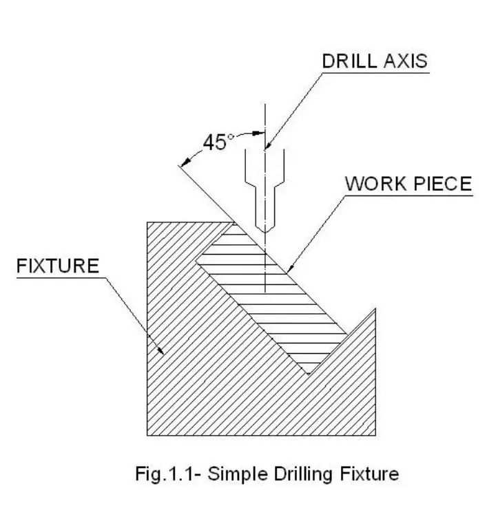
The above arrangement is a simple drilling fixture.
3-2-1 Principle of Fixture Design
For a fixture designer, the major portion of design time is spent deciding how to locate the work piece in the fixture.
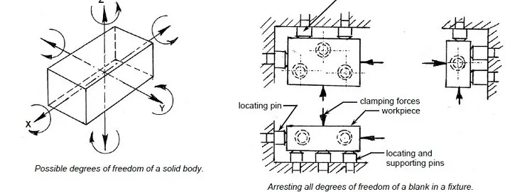
You know that any free body has a total of twelve degrees of freedom as below:
6 translational degrees of freedom**: +X, -X, +Y, -Y, +Z, -Z**
And 6 rotational degrees of freedom:
- Clockwise around X axis (CROT-X)
- Anticlockwise around X axis (ACROT-X)
- Clockwise around Y axis (CROT-Y)
- Anticlockwise around Y axis (ACROT-Y)
- Clockwise around Z axis (CROT-Z)
- Anticlockwise around Z axis (ACROT-Z)
You must fix all the 12 degrees of freedom except the three transitional degrees of freedom (-X, -Y and -Z) in order to locate the work piece in the fixture. So, 9 degrees of freedom of the work piece need to be fixed.
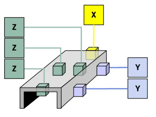
But, how? By using the 3-2-1 method as shoon below:
Rest the work piece on three non-collinear points of the bottom surface (XY), and you will be able to fix the +Z, CROT-X, ACROT-X, CROT-Y and ACROT-Y degrees of freedom**.**
Now, rest the work piece at two points of side surface (XZ), and you will be able to fix the +Y and ACROT-Z degrees of freedom.
Now, rest the work piece at one point of the adjacent surface (YZ), and you will be able to fix the +X and CROT-Z degrees of freedom.
So, you can successfully fixate 9 required degrees of freedom by using the 3-2-1 principle of fixture design.
5. Elaborate types of BIW Stations
An assembly line is a process in which car panel/car body parts are joined as the semi finished assembly moves from one station to another station until the final product is produced.
In the process of joining in assembly line , panels are moved from one section to another sections.Those sections are called Station.
In BIW fixture designing we have various stations which are used to locate the panels so that joining processes can be done.
Some of these stations are:
- Geo Station
- Respot Station
- Pedestal Weld/Rivet
- Loading Station
- Buffer Station
- Marriage station
- Sealing station
- Curing station
1. Geo station:
In this station geometry of two parts are fixed. it can be either using welding or riveting . In this station precision and geomatry of the finished product is defined Locating pins have closer tolerence of 0/-0.15.
Suppose the hole dia of panel is 16mm then the pin dia minimum can be 15.85.
Diameter of locating pins should be lesser than the panel hole dia. So Tolrence in locating pin is given in negative value.
2. Respot Station :
Once product comes out of the Geo Station and there are left out spots where spot welding or riveting is to be done. then it is moved to another station , that station is called Re-spot station.
These left out spots may be the due to clamp plan, cycle time,robot reach ability or any other various reasons.
In this station pins ahve tolrence upto 0/-0.28.
In this station , Pedestal gun is mounted on a tool and panel is manipulated manually or by robot to weld the panels.
Pedestal station is generally a Re spot station.
Re spot station and Pedestal station, both perform same kind of operation . but to decide whether to go for pedestal or a re-spot station some parameters needs to consider like cycle time, floor space, no. of welds, clamp plan, or size of the panel.
This station is used for loading of panel and same station is used to change the orientation of the if it is required in the upcomin station.
Sometime this station is used when Robots are unable to transfer panel from one station to another.
This station is used to make the balance between the process.
Some stations carry out procees in lesser time as compared to their respective stations.In that case panels can be stored in one sation so that assembly line process remains smooth.
In this station Sealant application is carried out.This process can be carried out manually or by using robots. Sealer is used in between two panels so that panels do not flatter due to friction.
In this Station inner and outer panels are joined. In this station to avoid the imprssion on the outer panel(A class surface), copper strips are used in betweenn the weld tip and A-class surface.
In this Station product recieved after sealing application, is kept idle at ambient temperature, which allows sealent to get dry with better bonding between the panel.
6. basic terminologies used in the BIW fixture
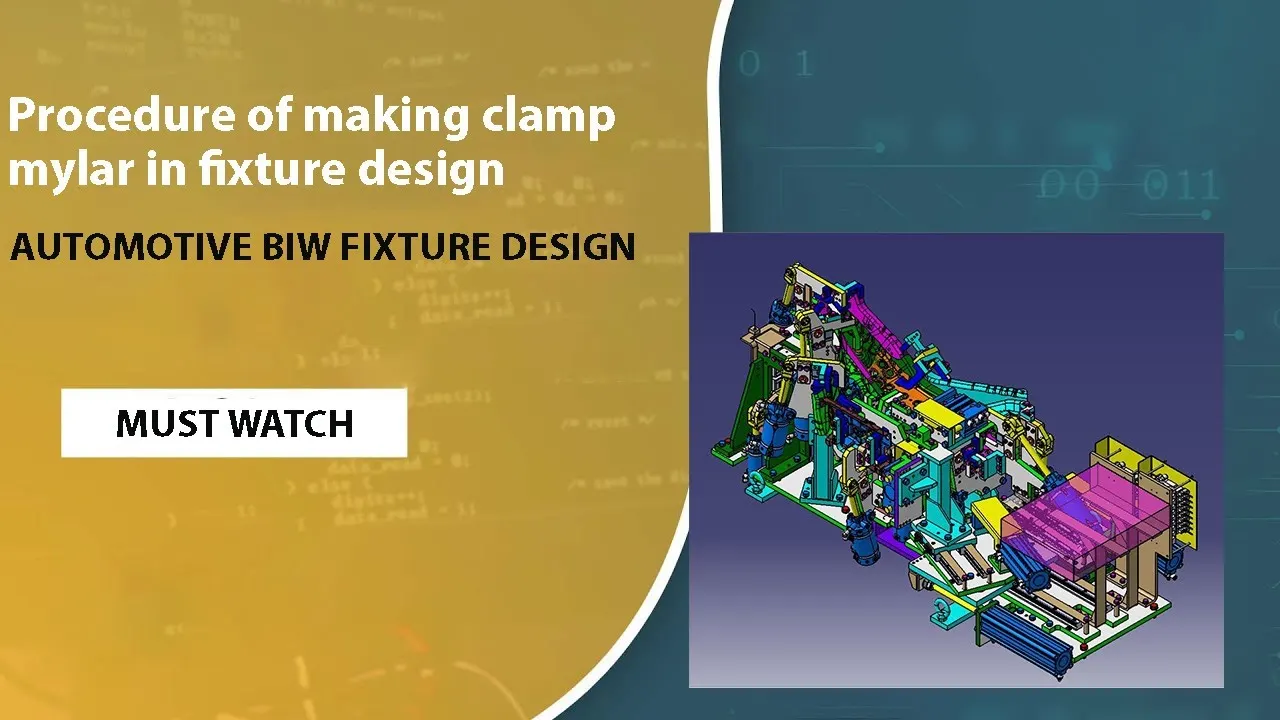
a) Mylars-Mylars is the component which holds the panel while operation. These are placed trom top side & trom bottom side
also. The top side Mylars called as Clamping Mylars & the bottom side Mylars called as Resting Mylars. Every clamping Mylars have resting
Mylars. It dont allow deformation of the part due to welding stresses.
B) Principle locating point (PLP) - These are the points which are used for the accurate location of the part to maintain the geometry of the
assembly. There are lots of holes on the panel which are not accurate due to stamping operation. The PLP are defined in the drawing. The
positional dimensions or relative dimensions are very precise in stamping & in fixtures also.
C) Risers - Risers are of different type like L-typer rises, Square tube riser etc. Riser is the manufacturing part which gives height to the
assemblies.
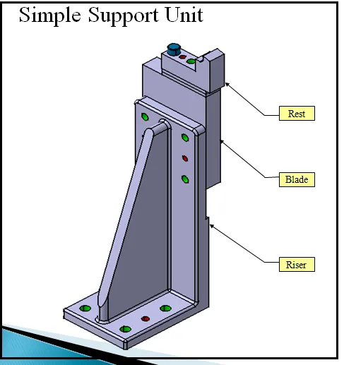
D) Blade- Blades are plates mounted on the riser. Other parts like cylinder, arms etc are mounted on the blade.
E) Shims - Shims are the small part which comes with the thickness of O.1mm, 0.2mm, 0.5mm etc. These will compensate the stackup
tolerance which reflects at the panel holding part called Mylars. We give tolerance to all the parts of the fixture. Due to this tolerance the
Mylars will either lift up or goes down from its defined position. If the Mylars goes down from the defined height it will make impression or
dent on the panel. If the Mylars lift up then there will be a distorsion due to welding stress. To adjust the Mylars At its defined position we
use shims so the panel won't deformed & also dont get any impression on it.
G) Hardwares - Hardwares are like the Hex head bolts, Allen Bolts, Hex nuts, Spring washers, Self locking nuts etc.
H) CMM - CMM stands for coordinate measuring machine. It is a device that measures the geometry of physical objects by sensing discrete
points on the surface of the object with a probe. It generates report my comparing the data with the CAD file data
1) Unit - The fixture is the assembly of different types of units to form a fixture. There are different units like pin unit, base unit, clamping
unit etc.
1) Number plates - Number plate is the aluminium embossed plate placed on the each unit for easily recognising the unit.
K) Name plate - The data like manufacturing company name, fixture type, Fixture weight etc. is embossed on the plate & joined to the
fixture
L) Clamp Arm - Clamp arm is the part of clamp unit which moves over a axis. Over clamp arm the Mylars are mounted.
M) Pivot - It is a axis about which the clamp arm will rotates.
N) Class A Surface/Skin surface - The outer panels of the car like hood, door, backdoor, fender.roof etc. are visible to the customer. Theouter panels should be asthetically very good. No any scratches or dent is acceptable over it. While designing the fixture to the skin surface
the clamping material should be soft, so that it could not able to left any impression or dent over skin. generally nylon or pu material is used
for clamping purpose.
O) Reed switches & sensors - These are the electric components used in automated fixtures. The reed switch is an electrical switch
operated by an applied magnetic field. The detects the panel is loaded or not is done by sensors.