Week 1:- Introduction to BiW and Fixtures Challenge
Introduction to BIW and Fixtures Challenge
Q1. What is BIW & define its parts?
Ans:
BIW, or Body In White, refers to the welded sheet metal components that constitute the vehicle's structural framework. This framework serves as the foundation for the assembly of various other components, including the engine, chassis, and both exterior and interior trims. At this stage, the body sheet metal components of the vehicle are assembled through welding and other joining techniques. The BIW structure is predominantly a steel shell composed of interrelated steel panels that are welded together. This structural assembly is essential for supporting all other subsystems within the vehicle.
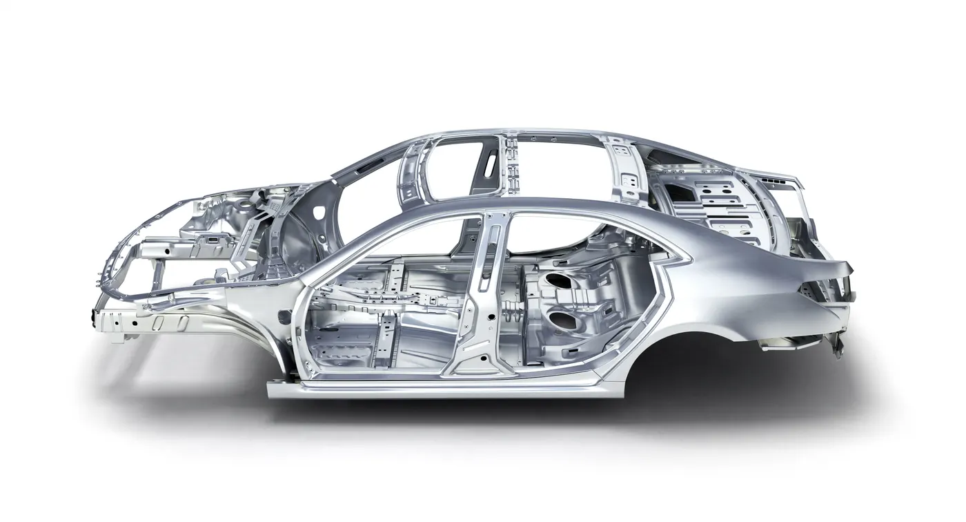
Fig: Body-in-White (BIW)
Several critical factors influence the design of BIW fixtures:
1. The number of components involved
2. The materials utilized
3. The need for internal structural reinforcement
The components of Body in White (BIW) primarily consist of five elements:
- Body Sides: This segment encompasses the right and left sides of the automotive sheet metal structure. The outer panels define the shape of the car body, while the inner panels serve to reinforce the structural integrity of the vehicle. The body sides, is further categorized into Inner and Outer Body Sides.
- Underbody: The primary function of the underbody shield is to protect essential components of the powertrain and steering systems effectively. The underbody is divided into three sections: the front end, the main floor, and the rear end.
- Closures: Automotive closures are vital to the safety and functionality of the vehicle. They include elements that secure the passenger compartment. The Closures are subdivided into Front Door, Rear Door, Hood, and Deck Lid.
- Roof: The roof of an automobile, or car top, is the portion situated above the passenger compartment. It protects the occupants against environmental factors such as sunlight, wind, rain, and other external elements. The roof can be classified into Inner and Outer Roof components.
- Fender: The primary purpose of the fender is to prevent debris, including sand, mud, rocks, liquids, and other roadway spray, from being projected into the air by the rotating tires.
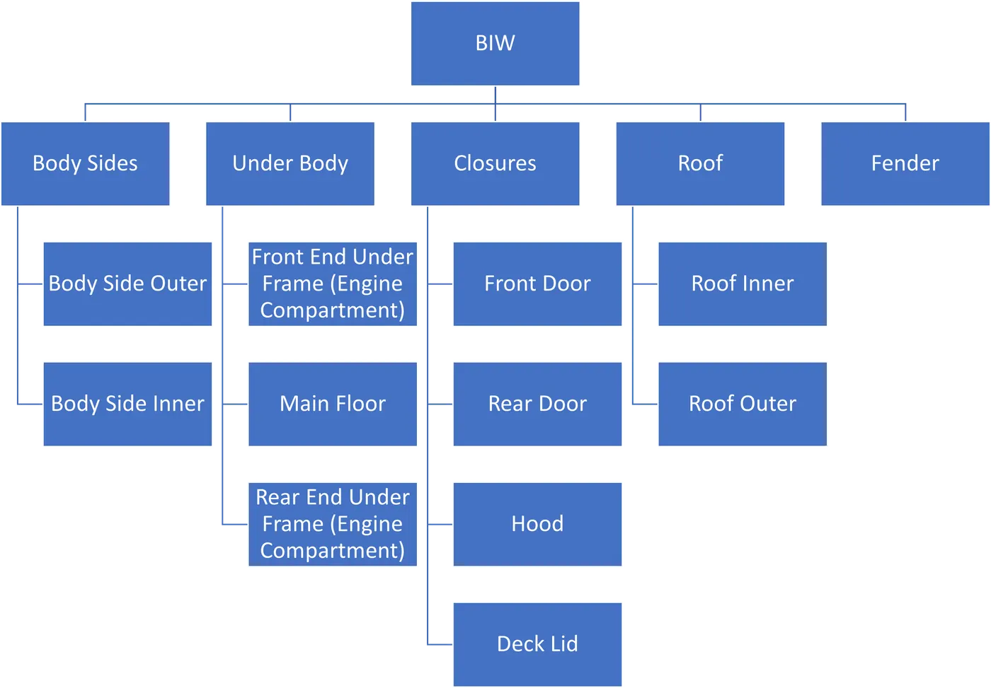
Fig: Components of BIW
Q2. What do you understand by BIW nomenclature?
Ans:
BIW nomenclature refers to the specific terminology assigned to various components within the sheet metal structure of a vehicle's body.
Body in White (BIW) encompasses a range of distinct parts and components, and the nomenclature serves the purpose of delineating these elements clearly. By utilizing precise names for each component, the identification and discussion of these parts become significantly more straightforward.
The nomenclature associated with BIW involves the systematic naming of every component comprising the vehicle body. These names can be categorized as subcomponents of the larger parts. Although regional variations in nomenclature may exist, the overarching objective remains consistent: to accurately designate individual automotive sheet metal components. Accompanying images further illustrate the BIW nomenclature.
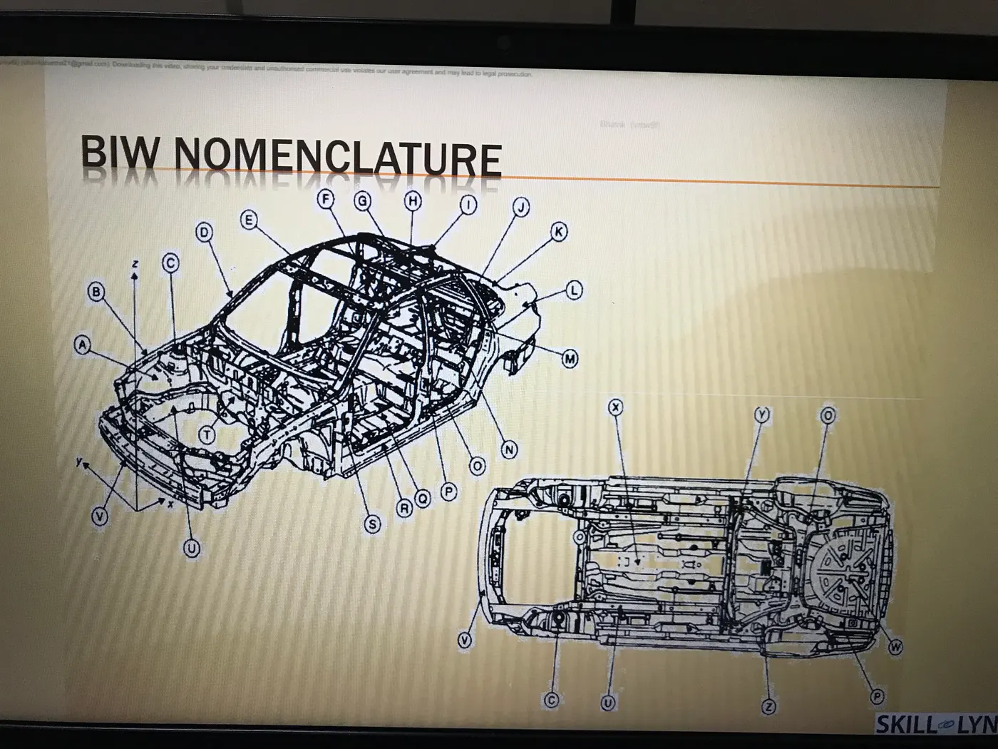
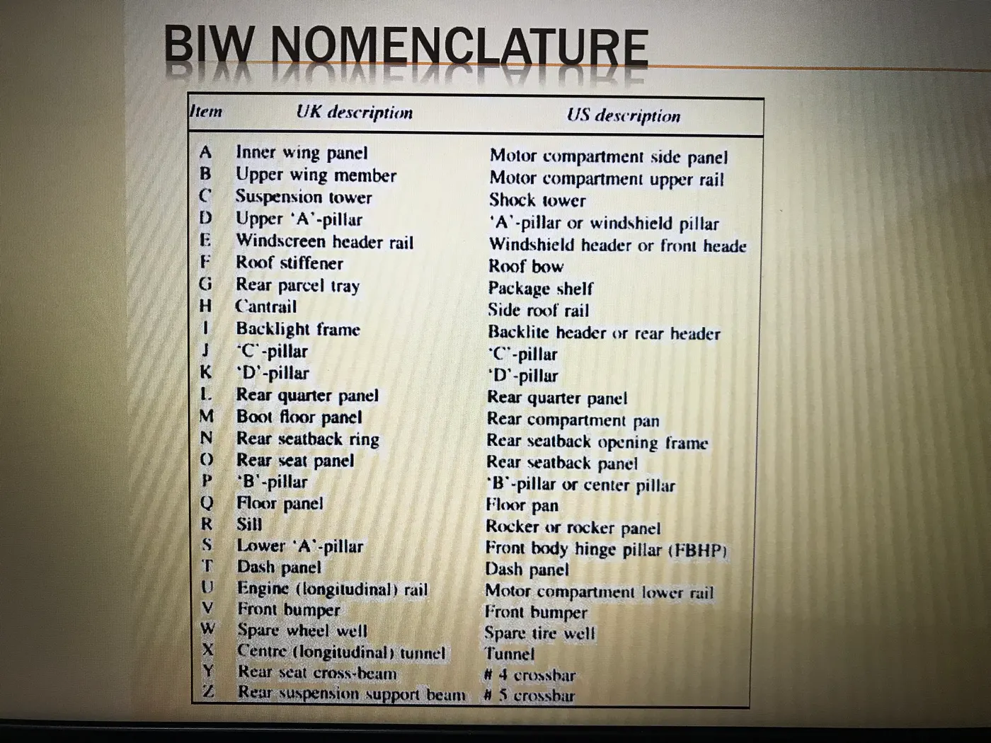
Fig: BIW Nomenclature
Q3. What is a fixture & its types?
Ans:
The fixture is an essential device utilized to secure the workpiece according to the 3-2-1 principle. It is imperative that the fixture holds the workpiece securely without inducing vibrations, distortions, or stresses. Furthermore, the fixture must not obstruct or interfere with the processing of the workpiece. To achieve this, the positioning of locating elements must be precise, clamping must be firm yet gentle, clamping components must be arranged away from the welding area, and the fixture must demonstrate considerable stability and rigidity to endure the stresses associated with welding.
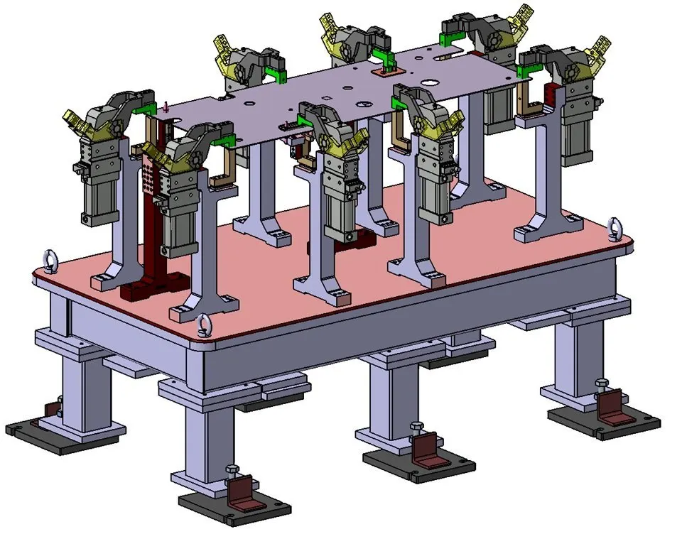
Fig: BIW Fixture Table
Types of Fixtures:
- Production Fixtures: This category of fixtures is employed for mass production purposes. They serve as the apparatus upon which automobile bodies are assembled before delivery to the end customer. Such fixtures must maintain high consistency in operation to preserve the geometry of the components. Given their role in mass production, they should be designed to be simple, rigid, and durable. Regular maintenance is essential to prevent errors and ensure longevity.
- Pre-Production Fixtures: Commonly referred to as prototype fixtures, these fixtures are utilized in the initial stages of operation. Once a pre-production fixture functions effectively, subsequent modifications can be implemented to enhance simplicity and reliability. These fixtures are generally applied in specialized situations or during trial phases of processing and production.
- Checking Fixtures: These fixtures are specifically designed for inspection and verification purposes, and no processing activities occur within them. They incorporate gauges for measuring dimensions, tolerances, and overall accuracy. In certain checking fixtures, the fixtures themselves remain fixed while Coordinate Measuring Machine (CMM) devices assess geometric accuracy. All locating elements and associated assemblies are evaluated through the use of gauges.
Q4. What is the basic principle of fixture design?
Ans:
The fundamental principle of fixture design asserts that any body possesses 12 degrees of freedom, comprised of 6 translational and 6 rotational degrees. To achieve effective fixture design, it is essential to constrain all 12 degrees of freedom.
The 6 translational degrees of freedom are classified as follows:
- Translation along the negative X-axis
- Translation along the negative Y-axis
- Translation along the negative Z-axis
In conjunction, the 6 rotational degrees of freedom are outlined as:
- Clockwise rotation around the X-axis (CROT-X)
- Anticlockwise rotation around the X-axis (ACROT-X)
- Clockwise rotation around the Y-axis (CROT-Y)
- Anticlockwise rotation around the Y-axis (ACROT-Y)
- Clockwise rotation around the Z-axis (CROT-Z)
- Anticlockwise rotation around the Z-axis (ACROT-Z)
Regarding the locating principle, the 3-2-1 method serves as a work-holding principle. This method employs three locating pins on the primary reference plane, which can be the XY, YZ, or ZX plane. Subsequently, two pins are positioned on the secondary plane, which is perpendicular to the primary plane, followed by one pin on the tertiary plane that is mutually perpendicular to both the primary and secondary planes.
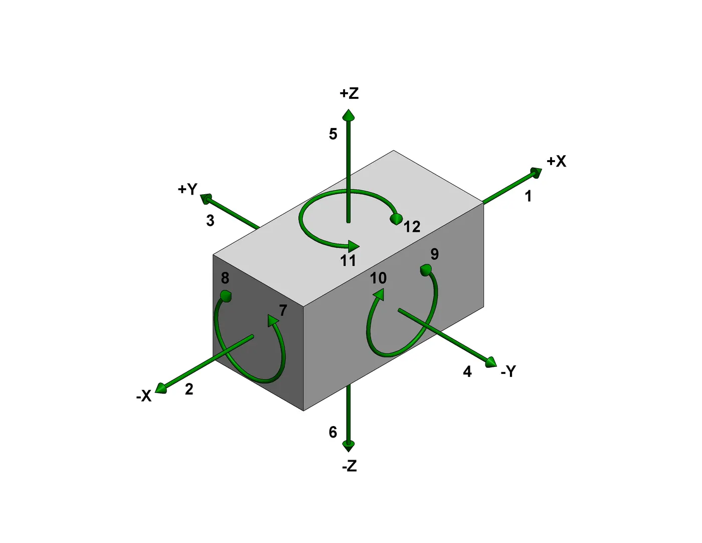
Fig: 12 Degree of Freedom
Q5. Elaborate on types of BIW Stations?
Ans:
The Body-in-White (BIW) assembly line is dedicated to the integration of various panels within designated zones, each of which is specifically categorized into stations such as the Underbody zone, Door zone, and Hood zone, among others. These zones are systematically classified into stations, which are further subdivided into tools, grippers, and stands.
A tool is defined as a fixture that securely holds automotive components together. Within the realm of tools, there are several classifications:
- Geometric Tool: This fixture is engineered to ensure the precise alignment of panel geometries that are to be welded together. The standard pin tolerance is maintained at approximately -0.15mm. For instance, if the panel hole size measures 20mm, the corresponding pin diameter should be calibrated to 19.85mm.
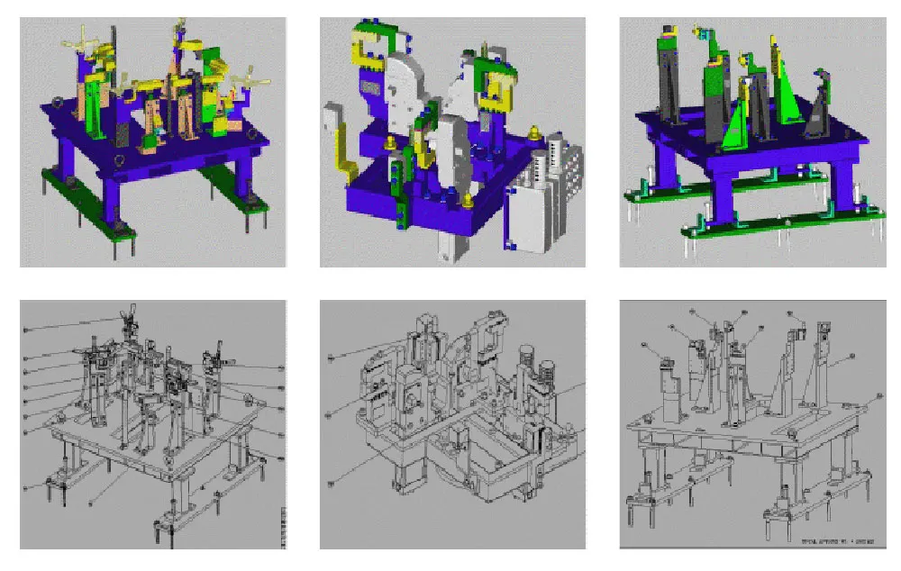 Fig: Geometric Tool Station
 - Re-Spot Tool: This tool serves the purpose of addressing any remaining welding spots that may not have been adequately achieved by the geometric tool. The tolerances for the re-spot tool are generally within -0.28mm. For a panel hole size of 20mm, the pin diameter should thus be 19.72mm.
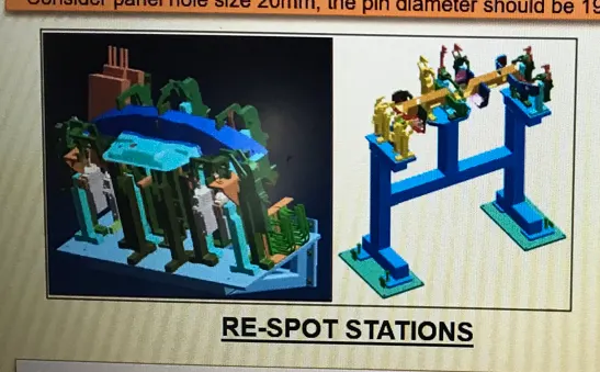 Fig: Re-spot Station
 - Marriage or Hemming Tool: This fixture is used to facilitate the union of the inner and outer panel assemblies, which can be accomplished through welding or hemming processes for closure panels.
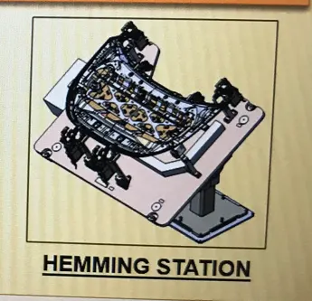 Fig: Hemming Station
 - Checking Station: This fixture is instrumental in verifying automotive parts or assemblies, ensuring that all coordinates, relative dimensions, and positions are within established tolerances.
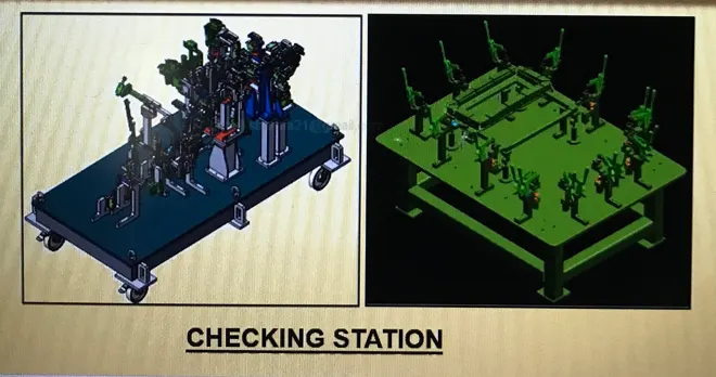 Fig: Checking Station
A gripper is defined as a mechanical device that secures the car panel and is attached to the manipulating end of a robotic arm. There are several types of grippers:
- Material Handling Gripper: Designed for transporting car panels from one tool or station to another.
- Process Gripper: Utilized for moving car panels while simultaneously executing processes such as pedestal welding, riveting, gluing, sealing, and others.
- Combo Gripper: This gripper is designed for transferring the car panel between tools, and it integrates a welding gun on one side for concurrent welding operations.
- Dual Gripper: Specifically designed to manage the movement of car panels, this device features two gripping sides.
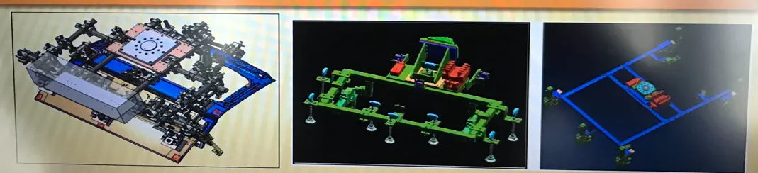
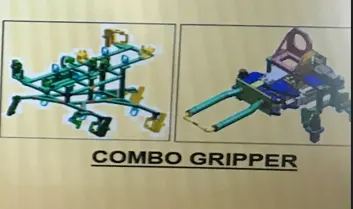
Fig: Material Handling Gripper Fig: Combo Gripper
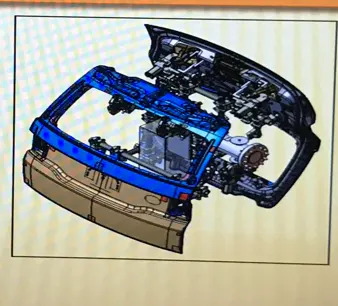
Fig: Process Gripper
The stand serves a dual purpose: it holds parts when they are not in use and provides a mounting surface for specific components. Various types of stands include:
- Gluing and Sealer Stand: This stand is equipped with a gluing or sealing gun, permanently affixed to a welded or standard base.
- Docking Stand: Employed for robotic operations requiring multitasking capabilities, the docking stand facilitates the seamless transition of grippers or guns after the completion of specific operations. This is particularly useful when the robot’s payload capacity or spatial constraints limit its ability to carry out both tasks simultaneously.
- Date Stamp Stand: This stand accommodates a date stamping device that embosses the panel with its respective date.
- Pedestal Gun Stand: A fixed stand that securely mounts the welding gun, which is permanently grouted to the floor.
- Take-Out Trolley: It is utilized to remove car panels from a robotic working cell between production cycles for inspection purposes.
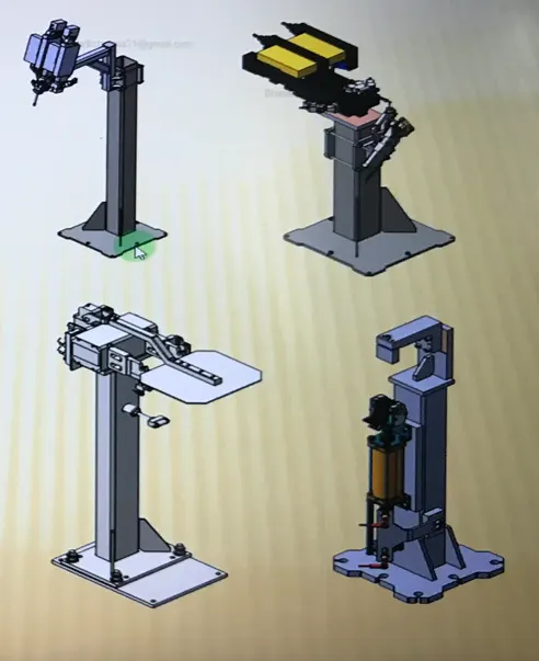
Fig: Gluing and Sealer Stand, Pedestal Gun Stand, Docking Stand, Date Stamp Stand
Q6. What are the basic terminologies used in the BIW fixture?
Ans:
- NC/ Mylars/ Fingers: These components serve to secure the panel from both the top and the bottom. The upper component is referred to as the clamping Mylar, while the lower component is termed the resting Mylar.
- PLP (Principal Location Points): These are the designated points utilized to accurately position the pins within the panel to ensure compliance with geometric specifications.
- Blade: Blades are plate-like structures that are affixed to the riser.
- Riser: The riser is a structural element that provides the necessary height for the workpiece.
- Shims: To rectify or balance tolerances within the fixture, thin plate-like structures known as shims are employed.
- Rough Locators: Rough locators serve to provide a preliminary indication, guiding the placement of the workpiece within specified limits.
- Hardware: The term "hardware" encompasses bolts, fasteners, and nuts.
- CMM: A Coordinate Measuring Machine (CMM) is employed to measure dimensions in accordance with specified data.
- Units: A fixture comprises various components, each referred to as a unit.
- Number Plate: To facilitate the identification of each unit within the assembly fixture, an embossed number is included.
- Co-ordinate Plate: The coordinate plate functions as a measuring tool for the CMM, establishing a reference point from which the coordinates of other holes are assessed.
- Name Plate: This plate contains essential information, including the date, type, panel number, and company name.
- Clamp Arm: The clamp arm features a rotating and movable structure.
- Class A Surface / Skin Surface: This refers to the surface that is visible to the end customer, which must be free of any dents or marks.
- Reed Switches: Reed switches consist of magnetic reeds mounted on cylinders; they are electronic switches activated by sensors.
- Sensors: Sensors are utilized to ascertain the positioning and accuracy of the unit in its designated location by providing necessary input.
- Pivot: The pivot serves as the point around which the clamp arm rotates.
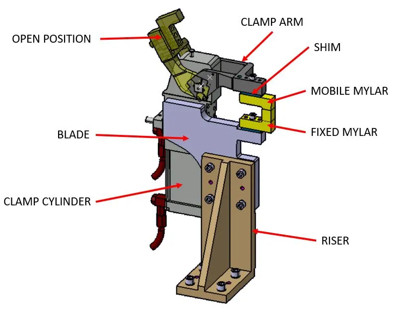
Fig: Basic Terminology