Week 1:- Introduction to BiW and Fixtures Challenge
1)What is BIW & and what are its parts?
The Body in White (BIW) is the term used in automotive manufacturing to describe the stage where a vehicle's body structure is assembled but has not yet undergone painting or trim installation. It represents the skeleton of the vehicle, providing the foundational structure onto which other components are later added. Now, let's delve into the specific parts of the BIW you mentioned:
1.Body Side: The body sides refer to the vertical panels that form the outer sides of the vehicle, extending from the front fender to the rear quarter panel. These panels provide structural support and contribute to the overall aerodynamics and aesthetics of the vehicle. They are typically stamped from sheet metal and welded to the floor pan and roof structure.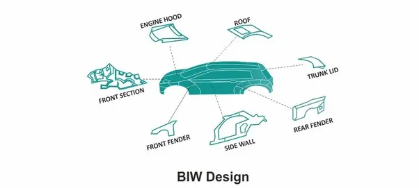
2. Upper Body: The upper body encompasses the roof, pillars, and upper portions of the vehicle's side panels. It plays a critical role in providing rigidity and crash protection to the occupants. The roof panel spans horizontally across the top of the vehicle and is welded or bonded to the side panels and pillars. The pillars, including the A, B, and C pillars, provide vertical support and help define the vehicle's silhouette.
3. Closures: Closures are the movable panels of the vehicle, including doors, hood, trunk lid, and tailgate. These panels allow access to the vehicle's interior and cargo areas. Doors, for example, are attached to hinges and equipped with latches for opening and closing. Trunk lids and hoods are also hinged to the vehicle's structure and feature mechanisms for secure closure.
4. Roof: The roof panel forms the uppermost portion of the vehicle's structure, providing protection from the elements and contributing to overall aerodynamics. It is typically stamped from sheet metal and welded or bonded to the body sides and pillars. The roof may also incorporate features such as sunroofs or roof rails for added functionality and styling.
5. Fenders: Fenders are the curved panels located above the wheels, covering and protecting them from road debris and splashes. They are typically stamped from sheet metal and welded or bolted to the vehicle's body sides and upper body structure. Fenders also contribute to the vehicle's aesthetics and aerodynamics, helping to streamline airflow around the wheels.
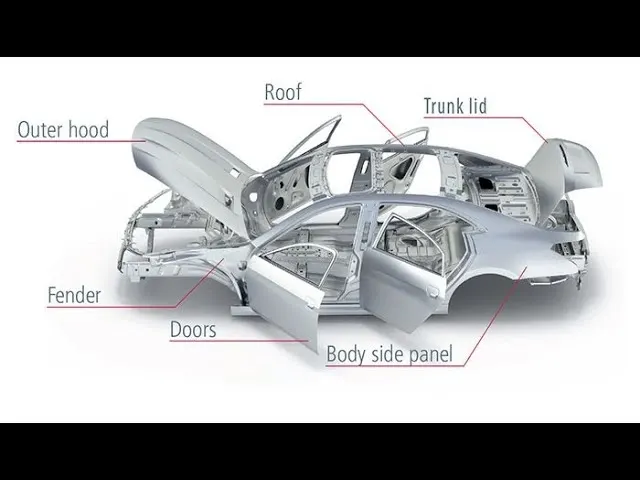
These components collectively form the Body in White of a vehicle, providing the essential structure and support for the rest of the assembly process. Each part serves a specific function in terms of structural integrity, safety, aesthetics, and functionality, ultimately contributing to the overall performance and appeal of the vehicle.
2) What do you understand by BIW nomenclature?
BIW nomenclature refers to the system of naming or labeling the various components and parts of the Body in White (BIW) in automotive manufacturing. It involves assigning specific names or codes to different BIW parts to facilitate communication, documentation, and assembly processes throughout the manufacturing chain.
The BIW nomenclature typically includes unique identifiers for each component, such as body panels, structural members, closures, apertures, and mounting points. These identifiers may consist of alphanumeric codes, part numbers, or descriptive names that help differentiate one part from another and ensure accuracy and consistency in production.
By using a standardized BIW nomenclature, automakers, and suppliers can streamline communication between design, engineering, manufacturing, and assembly teams. It allows for clear identification and tracking of parts throughout the production process, from initial design and prototyping to final assembly and quality control.
Additionally, BIW nomenclature helps maintain an organized and efficient manufacturing environment by enabling quick and accurate retrieval of parts, reducing errors, and improving overall production efficiency. It also facilitates troubleshooting and maintenance activities throughout the vehicle's lifecycle by providing a common language for referencing components and assemblies.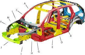
3) What is a fixture & its types?
A fixture is a device utilized in welding processes to securely hold the workpiece in place, typically following the 3-2-1 Principle. These fixtures are comprised of multiple units assembled together to accommodate the car panels and are affixed onto a base unit. Stability and rigidity are essential characteristics of welding fixtures, ensuring they can endure the stresses of welding operations.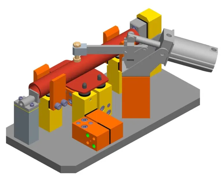
Welding fixtures serve the purpose of maintaining the required shape of parts, from smaller components to larger ones like those found in planes. Before welding, parts are positioned within the fixture to achieve the desired shape. Subsequently, the parts are clamped using a clamping unit, enabling welding operations to commence.
There are various types of BIW fixtures, including:
1. Production Fixtures: Designed for mass production, these fixtures prioritize high consistency throughout operations to uphold part geometry. Materials used are rigorously tested for hardness and aesthetics. Quality checks are conducted to ensure dimensional accuracy and tolerance maintenance. Production fixtures should be easily maintainable, with minimal assembly and disassembly time to optimize efficiency.
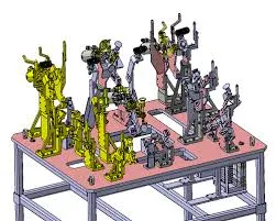
2. Pre-production Operation Fixtures: These fixtures serve as prototypes to evaluate the feasibility of initial batch production and identify areas for improvement before full-scale production. PPO fixtures establish benchmarks and criteria for rectifying errors encountered during pre-production operations. Although they involve manual operations and require significant time and resources, they play a crucial role in streamlining the transition to production fixtures.
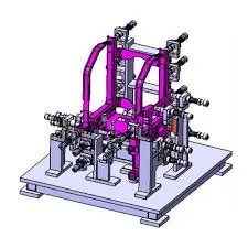
3. Checking Fixtures: Primarily used for dimensional inspection, checking fixtures does not perform welding, gluing, or hemming operations. Gauges are employed to measure the dimensions and tolerances of parts, comparing the data with design specifications to verify part quality. Additionally, checking fixtures assesses the geometry of welded parts to ensure adherence to required dimensions and geometry standards.
4) What is the basic principle of fixture design?
The 3-2-1 principle is a fundamental concept used in fixture design to properly locate and secure a workpiece during manufacturing processes. Fixture designers devote a significant amount of time determining how to restrict all twelve degrees of freedom (DOF) of the workpiece, which include six translational DOFs and six rotational DOFs.
The primary locator consists of three supports placed underneath the workpiece, positioning it on the primary locating surface or datum. This arrangement restricts five degrees of freedom, including axial movement downward along the Z-axis and rotation about the X and Y axes.
Secondary locators, typically two in number, are positioned on the secondary surface to further restrict three degrees of freedom. These include axial movement along the Y+ axis and rotation about the Z-axis.
The tertiary locator, usually placed at the end of the part, restricts one degree of freedom, which is axial movement along the X-axis.
Collectively, these six locators restrict nine degrees of freedom, leaving three degrees of freedom to be constrained by clamps. Using the minimum number of pins for maximum DOF restriction helps streamline assembly and disassembly processes.
Jigs and fixtures are indispensable tools in mass production for holding workpieces in precise positions. Various types of fixtures, such as drilling, milling, and welding fixtures, are utilized across industries. The 3-2-1 method serves as the foundational principle for designing all types of fixtures, ensuring accurate and efficient manufacturing processes.
5) Elaborate on types of BIW Stations.
BIW stations play a critical role in the assembly line, facilitating the construction of the Body in White components. These stations are categorized into various types, each serving specific functions and equipped with distinct tools and equipment. Let's explore the different types of BIW stations in detail: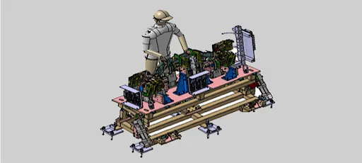
1. Tool Stations:
a)Geo Fixtures: These fixtures are instrumental in tack welding components together, defining the geometry of the part. Each part is precisely located using locating pins, ensuring tight accuracy standards. Geo fixtures maintain a maximum tolerance of ±0.02 mm for individual machine parts, with positional accuracy within -0.15 mm.
b) Re-spot Fixtures: Reserved for completing remaining tack welds after initial welding operations. They are crucial for maintaining part geometry and preventing deformation during transportation. Re-spot fixtures also adhere to stringent positional tolerance standards, typically -0.28 mm.
c) Marriage/Hemming Fixture: This station facilitates the assembly of different components using various joining techniques like welding, gluing, or riveting. It serves as a pivotal point where various assemblies are brought together, akin to a marriage of different parts.
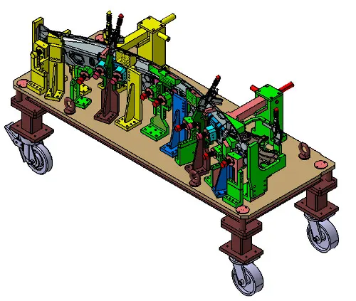
d) Framer Fixture: Positioned after the marriage fixture, the framer fixture involves attaching the roof to the assembled components, forming a complete frame structure.
e) Checking Fixture: Checking fixtures are utilized to verify assembly quality, dimensions, and tolerances. They can be gauge-type fixtures where the workpiece is held for dimensional inspection or fixed-type fixtures where CMM (Coordinate Measuring Machine) measures coordinates to compare with CAD data.
2. Gripper Stations:
a) Material Handling Gripper: These grippers are employed for transporting materials between stations.
b)Process Grippers: Used for specific processes like gluing, welding, or riveting, in addition to material handling.
c) Combo Gripper: Capable of performing multiple tasks, such as material handling and specific processes like gluing or welding.
d) Dual Gripper: Utilized when both left-hand and right-hand parts need to be handled simultaneously, facilitating efficient operations.
3. Stand Stations:
Stands are utilized for holding parts when not in use or for mounting specific components. Various types of stands include:
a) Pedestal Stands: Used for mounting welding guns or gluing/sealing guns, providing stability during operations.
b) Gluing & Sealer Stand: Fixed stands for mounting gluing or sealing guns, essential for adhesive application processes.
c) Docking Stand: Utilized to store equipment not in use for the current operation, ensuring seamless transitions between tasks.
d) Date Stamp Stand: Houses stamping devices for imprinting serial numbers, batch numbers, or dates on manufactured products.
4. Miscellaneous Stands: These stands serve miscellaneous functions and include:
a) Curing Stands: Used for cooling down glued components after the gluing process.
b) Buffer Stands: Serve as buffer stock areas for storing assemblies between operations or during machine maintenance.
c) Take-out trolleys: Used to transport panels for inspection or rectification during the production cycle.
d) Conveyor: Rotating paths for transporting parts to the next station in the assembly line.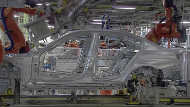
Each type of BIW station plays a crucial role in ensuring the smooth operation of the assembly line and the production of high-quality Body in White components.
6) What are the basic terminologies used in the BIW fixture?
Here are some basic terminologies used in BIW fixtures: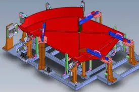
A) NC/Mylars/Fingers:
Mylars are components that hold the panel in place during welding. They are placed both from the top and bottom sides of the panel. Clamping Mylars are located on the top side, while Resting Mylars are on the bottom side. These prevent the deformation of the part due to welding stresses.
B) Principle Locating Point (PLP):
PLPs are points used for accurately locating the part to maintain its geometry. They compensate for inaccuracies in panel holes caused by stamping operations. PLPs are precisely defined in drawings to ensure accurate positioning.
C) Risers:
Risers are components that provide height to assemblies. They come in different types, such as L-type risers and square tube risers.
D) Blade:
Blades are plates mounted on fixtures, onto which other parts like cylinders or arms are attached.
E) Shims:
Shims are small components with thicknesses ranging from 0.1mm to 0.5mm. They compensate for stack-up tolerances, ensuring that Mylars remain at their defined positions without causing deformation or impressions on the panel.
F) Rough Locators:
Rough locators serve as guides for operators to ensure correct orientation when placing parts in the fixture, aiding in foolproofing.
G) Hardware:
Hardware includes components such as hex head bolts, Allen bolts, hex nuts, spring washers, and self-locking nuts used in fixture assembly.
H) CMM (Coordinate Measuring Machine):
A CMM is a device used for measuring the geometry of physical objects by sensing discrete points on the object's surface with a probe. It generates reports by comparing measured data with CAD files.
I) Unit :
Units are assembled to form a fixture and include various types such as pin units, base units, and clamping units.
J) Number Plates:
Number plates are aluminum plates placed on each unit for easy identification.
K) Nameplate:
Nameplates contain data such as the manufacturing company's name, fixture type, and weight, embossed on the plate and attached to the fixture.
L) Clamp Arm:
The clamp arm is part of the clamp unit that moves to secure the panel. Mylars are typically mounted over the clamp arm.
K) Pivot:
The pivot is the axis around which the clamp arm moves.
L) Class A Surface/Skin Surface:
These refer to the outer panels of the car, such as the hood, door, fender, etc., which are visible to the customer. Clamping materials used for these surfaces are soft to prevent any impressions or dents. Nylon or PU materials are commonly used for clamping.
O) Reed Switches & Sensors:
Reed switches are electrical switches operated by a magnetic field, while sensors detect whether a panel is loaded onto the fixture in automated processes.