Week 1 : Exploring the GUI of GT-POWER
Exploring the GUI of GT-POWER
1. GT-SUITE is a popular 1D simulation tool with capabilities and libraries aimed at a wide variety of applications and industries. It offers engineers functionalities ranging from fast concept design to detailed system or sub-system/component analyses, design optimization, and root cause investigation.
The foundation of GT-SUITE is a versatile multi-physics platform for constructing models of general systems based on many underlying fundamental libraries:
- Flow library (any fluid, gas or liquid, or mixture)
- Acoustics library (both non-linear and linear)
- Thermal library (all types of heat transfer)
- Mechanical library (kinematics, multi-body dynamics, frequency domain)
- Electric and Electromagnetic library (circuits, electromechanical devices)
- Chemistry library (chemical kinetics)
- Controls library (signal processing)
- Built-in 3D CFD and 3D FE (thermal and structural)
GT-ISE (Integrated Simulation Environment)
GT-ISE is the interface where models are built, simulation settings are declared, and simulations (both single and batch) are launched. It is a 2-D environment where various objects are brought into a project map and connected together linking the entire model as a whole.
additional features:
• Compound templates for users to make their own templates, with their own help files, plots, RLTs, and control signals.
• 2-D scale viewer shows scale view on input geometry and 3-D viewer of flowsplit geometry
• Run-time monitors display results during the simulation, and 'ActiveDial' allows inputs to be varied dynamically in simulation.
• CaseSetup and DOESetup, for defining multiple simulations within one file and the parameters that
change from case to case, including formulas and functions.
• Models can be annotated with text and figures
GT-POST
Once the simulation is run, results may be sent to GT-POST, a graphical interface that enables viewing and manipulating of the data collected from the simulation. GT-POST contains the following functions and
more:
• Graphically based data post-processing
• Quick generation of 2-D and 3-D plots of any quantity
• Ability to combine data from different cases, different simulations or tests into one plot
• Re-usable post-processing templates allow instant cross-plotting of results from different
simulations
• Ability to read data directly from ASC/Excel files with database capabilities for fast and flexible
access to measurement data.
• Import or Export data to/from ASCII or MS/EXCEL files
• Various math operations that can be performed on data in all plots (sum, difference, integral, derivative, FFT…)
• Animation of transient processes
• User-definable tabular output of the computed result
GEM3D Pre-processor
GEM3D is a 3D graphics tool to convert a 3D CAD file into a model suitable to open in GT-ISE. It will assist the user in efficiently finding the effective length, diameters, bends, volume, etc. of complex 3D shapes, and turn them into GT-SUITE-equivalent parts, such as pipes and flowsplits. It also has a model-building capability that is especially useful for building mufflers, air-boxes, and plenums, for example, including options to add baffles, perforates, pipe positions, and wools.
COOL3D Underhood Modeling Preprocessor
COOL3D is a 3D preprocessor application tool used to build complex underhood models for thermal modeling applications. It includes provisions for detailed modeling of heat exchangers, fans, shrouds, various positions of inlet and outlet flow, and blockages from structural elements. It then outputs a discretized model of the cooling space that can then be opened in GT-ISE and readily connected to other systems, such as the liquid coolant flowing in the internal passages of a radiator or the hot air flowing in the internal passages of a charge air intercooler.
VTDESIGN Valvetrain Design Tool
VTDESIGN is a graphical preprocessing tool for valvetrain and cam design. It has several capabilities, which include:
• Cam design tool for creating cam profiles, including the ability to create and store different design strategies (i.e. different sets of constraint matches).
• Cam-profile reverse-engineering tool for converting an existing cam profile measurement back into an equivalent mathematical fit.
• Graphical tool for building and visualizing the motion of commonly available cam and lifter mechanisms.
2.
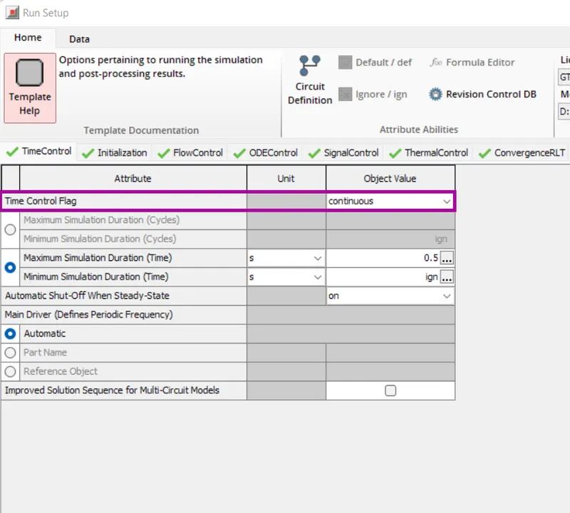
Defines the global simulation type with regard to time. One of the following options:
- periodic indicates that the model contains at least one circuit which contains a periodic event (i.e. engine cylinder “cycle”) and therefore requires tracking of results with respect to angle over each cycle. Any model that includes an ' EngineCrankTrain', ' CrankAnalysis', or ' EngineCrankShaft' part should use the periodic option. Note that the simulation duration for a periodic simulation can be specified in cycles or in time, whichever is most convenient.
- continuous indicates that the simulation includes no periodic event, and therefore has no need to track results with respect to a cyclic angle. This is the typical setting for models that contain only quasi-steady fluid circuits such as coolant or underhood air. The simulation duration for a continuous simulation is typically specified in time
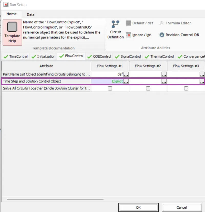
Time step and solution control
To define if the simulation should be implicit, explicit, or Quasi-steady. Name of the ' FlowControlExplicit', ' FlowControlImplicit', or ' FlowControlQS' reference object that can be used to define the numerical parameters for the explicit, implicit, or quasi-steady flow solver, respectively.
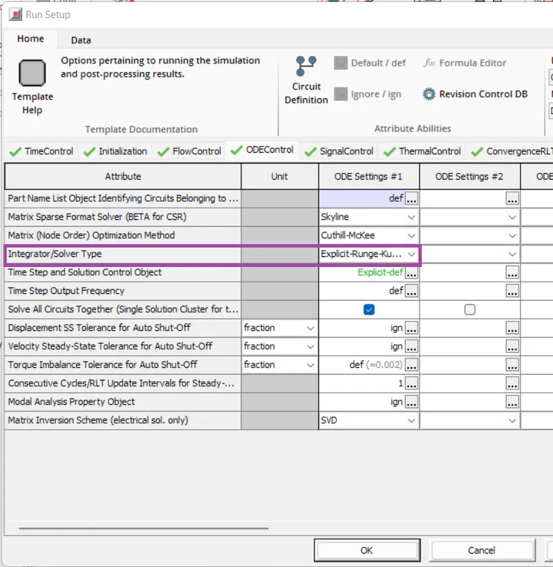
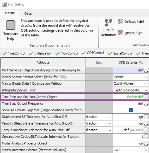
Integrator/Solver type
Integrator/solver type used in the time-marching of all ODEs including mechanical, electrical, and magnetic libraries. For recommendations based on the application, please see the color-coded table immediately following this text.
Explore intercooler tutorial
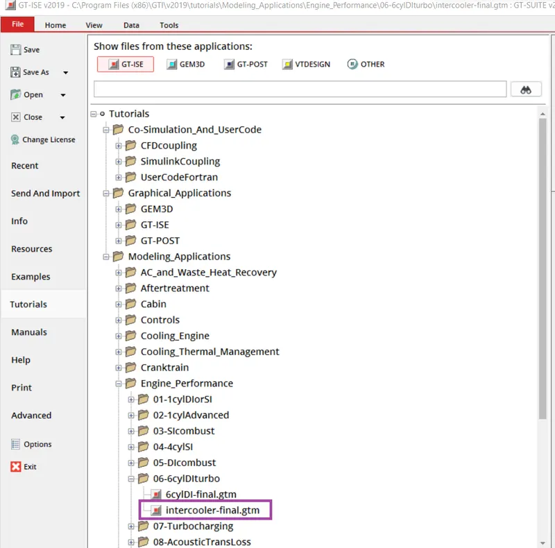
The intercooler tutorial is found in the Engine performance folder from modeling application tutorials.
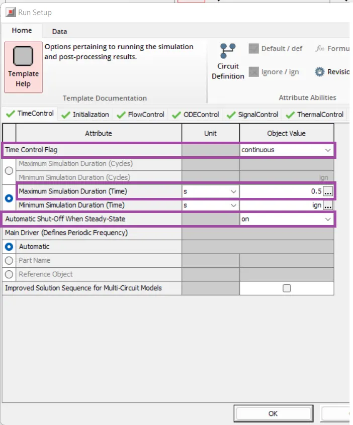
The simulation was set to run for 0.5 seconds and it is continuous time control. Automatic shut-off when steady state was turned on, so when the simulation reaches steady state before the given maximum simulation duration, it automatically stops the simulation.
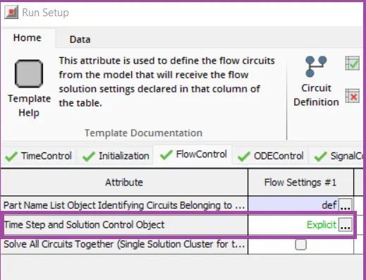
Here explicit time step method is used as the simulation time is less and The explicit method is recommended for the large majority of engine performance lubrication, injection, or hydraulic system simulations over small time scales
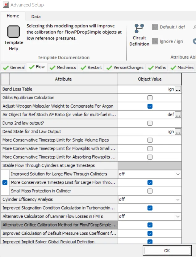
Advanced setup
Plot setup
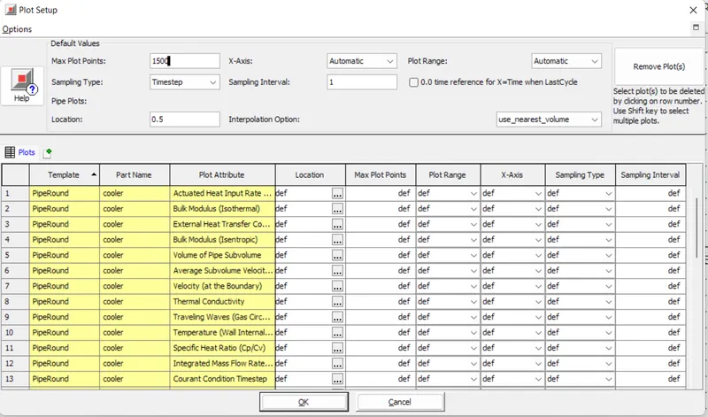
selecting the cooler part on the project map and selecting to plot many variables. we get to see what are all the parameters that are selected for plotting in the plot setup.
Output setup
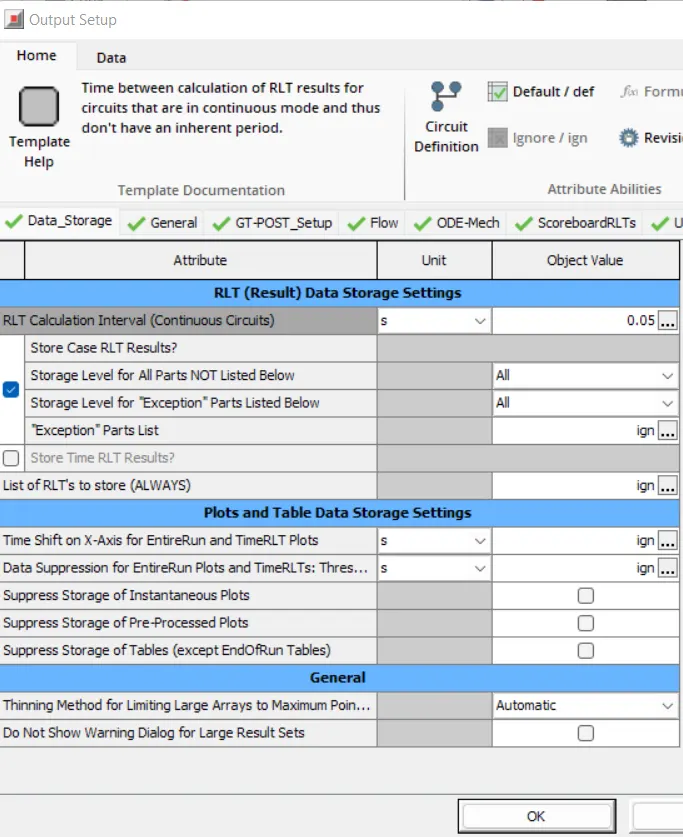
in the output setup, the Time between the calculation of RLT results for circuits that are in continuous mode and thus don't have an inherent period. this defined what period solutions are updated and saved.
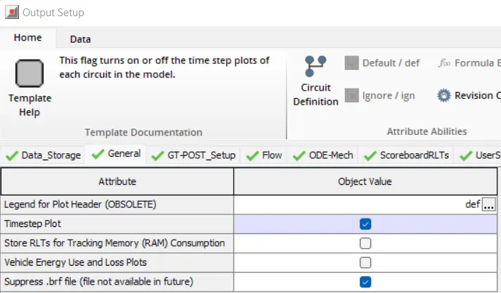
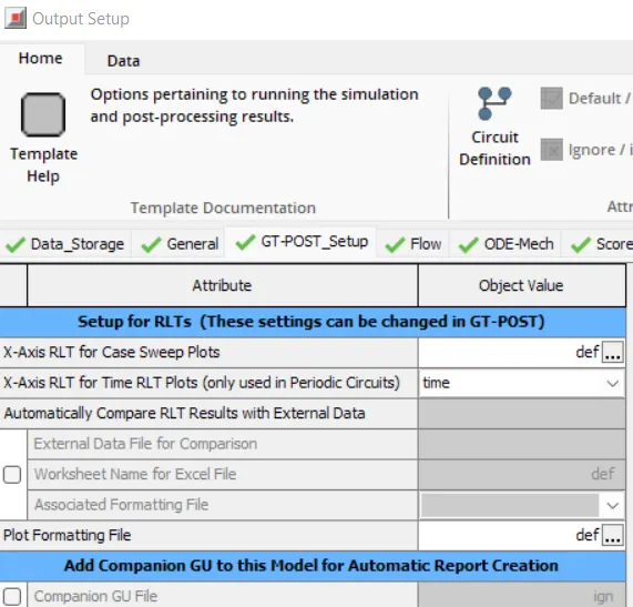
3. Problem
Given
- Diameter of the cooler inlet and outlet pipe= 50 mm
- Length of the CAC= 1000 mm
- Inlet mass flow rate = 1200 kg/ h at 100 degC
- Outlet pressure 2 bar at 30 deg C
Result:

The end flow template is used to impose the mass flow rate.
Following the intercooler template, the values are updated with the given values and the case is set up for 0.5 seconds of total simulation time and solved explicitly.
After running the setup the GT-Post is automatically open and the view results option will turn on after running the simulation.
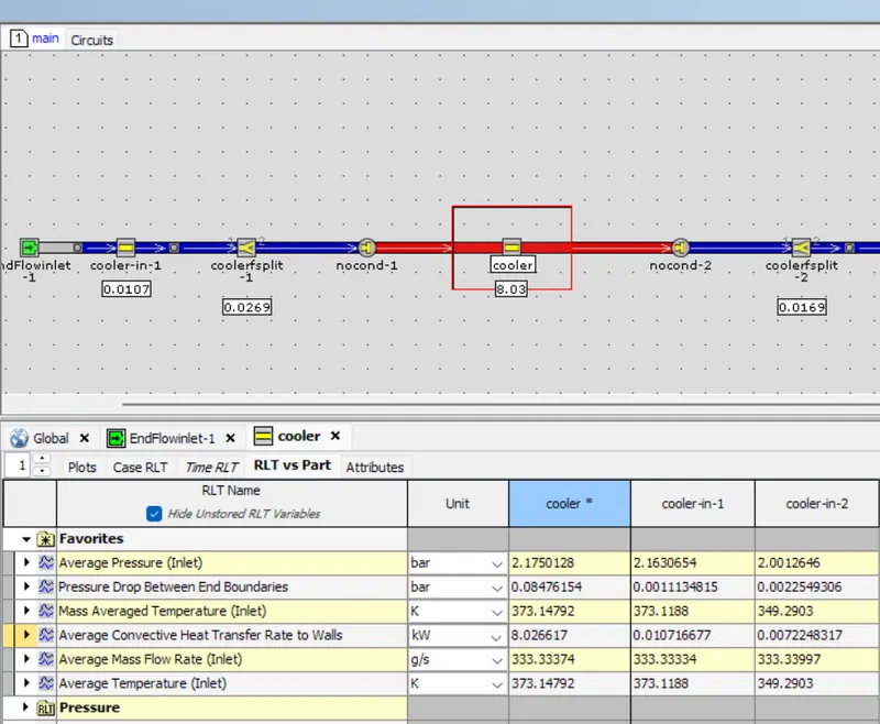
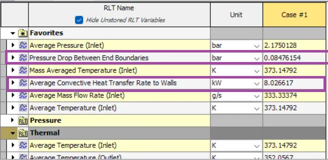
From the GT-Post when we select the part and RLT vs Part for the results, we can observe the table of results and can be found that 0.08476 bar is the pressure drop across boundary and a convective heat transfer rate across CAC is 8.0266kW.