Week 1 : Exploring the GUI of GT-POWER
The below image shows the various modules of GT Suite
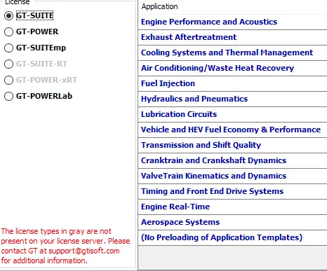
A few have discussed breifly
Engine Performace and Acoustics : We can find the performance parameters of the engines such as Brake Thermal Efficiency ,Brake Power and Indicated Power , Volumetric efficiency ..etc of the engine .
Exhaust After treatment : This modules does the 1d simulation for after treatment of exhaust gases like SCR : selective catalytic redution ,Exhaust Gas Recirculation and all those activities which are dealing with exhaust gases
Cooling System and Thermal Management: Cooling system deals with the Coolant load for the heat rejection of the engine, and Heat balance from the total heat supplied.
Fuel Injection : Injector configuration for the pressure in case CI and SI engines
For the intercooler tutorial we follow the steps as shown below
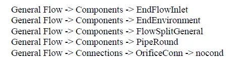
we take these templates , drag and drop them accordingly
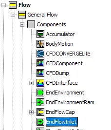
For the endflow inlet
the below values were entered at mass flow rate and Temperature
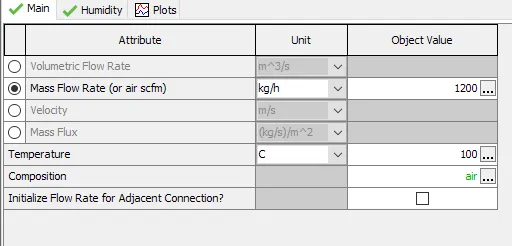
for the composition value we select fluidmixture and then select air
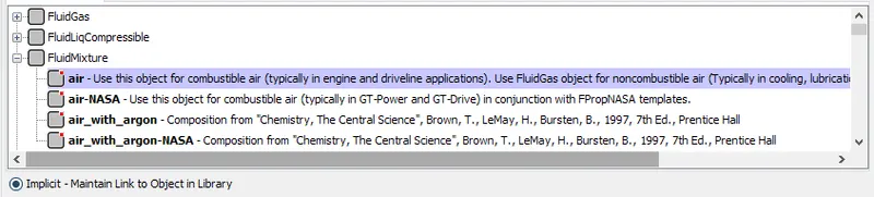
We now select the
pipe round
we name it as cooler -inlet-1
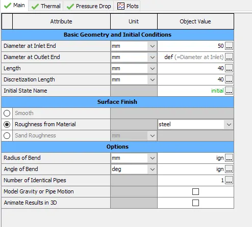
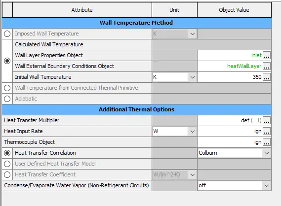
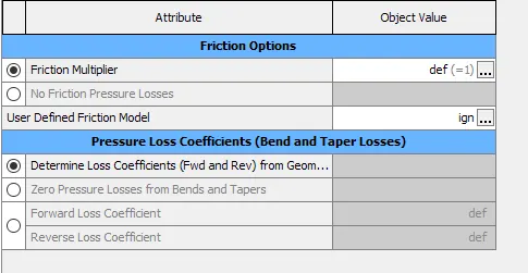
we make a copy of the same and name it as cooler inlet 2
COOLER
The cooler diameter is 50mm and the length is 1000 mm
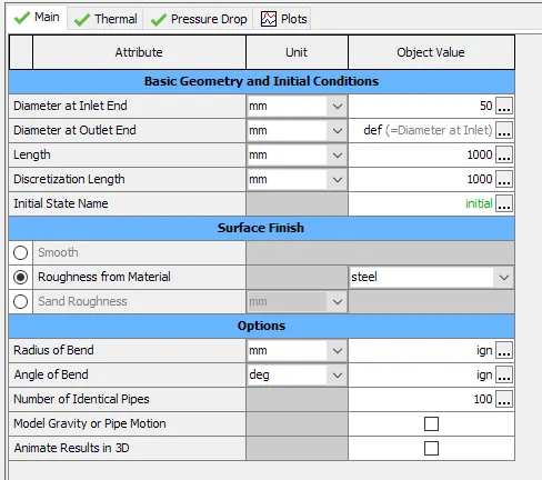
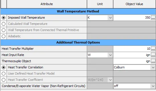
flow Split general
we make two splits with names flowsplit-1 and flowsplit-2
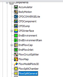
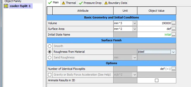
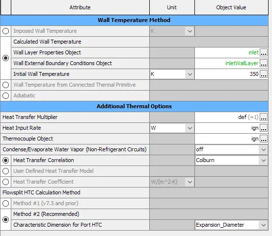
we make a copy of flow split and name it as flow-split-2
EndEnvironment
By using this we create outlet object with the given pressure and temperature
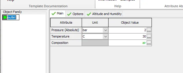
and later join them by linking and eventually we run the solution
Circuit

Running the Setup
Plot Setup
For plotting the result we can directly select the object at which section we want the plots, and select it from various properties like fluid , thermal etc.
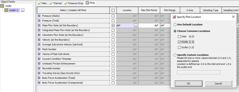
and the location at which the value is take from can also be selected
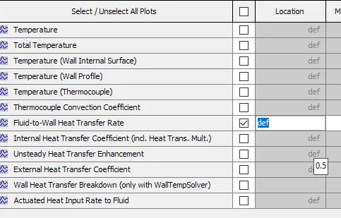
Since we require both the pressure drop and heat transfer we selected those and proceeding with the setup
RunSetup
The time control flag attribute can be accesed from Run Setup,
The simulation time is chosen for 0.5 -s
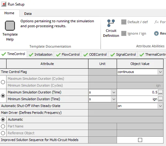
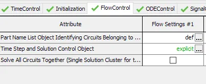
Further more from flow control we can access time step and solution control
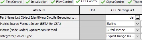
The solver control can be accessed from ODEControl Tab , for the present simulation we are using Explicit -Runge-Kutta
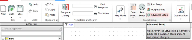
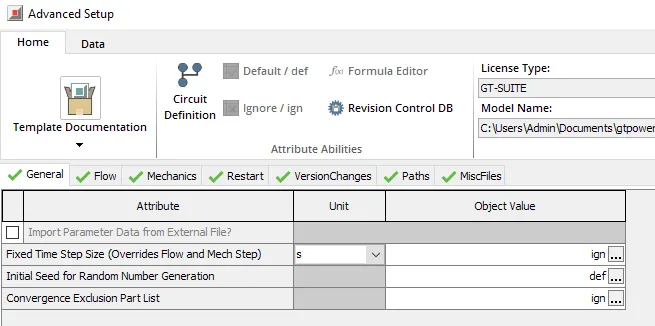
Advance setup
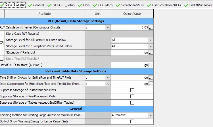
Output Setup

Results
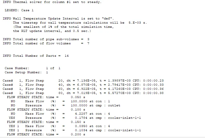
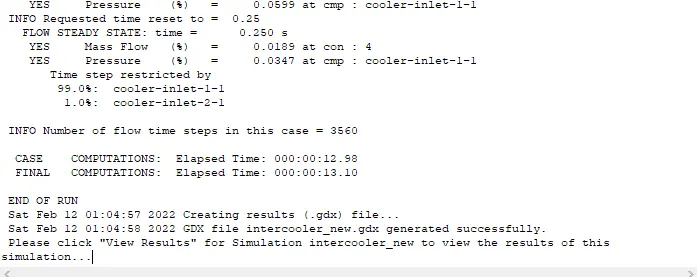
Once setup is complete we run the solution by using the RUN icon
that starts GTpost
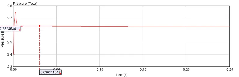
The pressure plot in the cooler wrt time
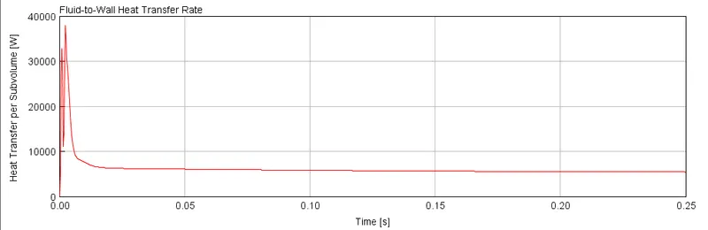
The heat transfer rate
The heat transfer rate at final time step is around 5426.4-W