Week 1 : Exploring the GUI of GT-POWER
1. Explore the GUI of GT SUITE and list down modules available with brief description.
GT-SUITE:
- GT-SUITE is the simulation tool with capabilities and libraries aimed at wide variety of applications and industries.
- It offers engineers functionalities ranging from fast concept design to detailed system or sub-system / component analyses, design optimisation, and root cause investigation.
Why You Should Choose GT-SUITE
Industry’s Tool of Choice
- It is recognized worldwide as the Industry Standard for system simulations.
- Used by most leading OEMs and suppliers.
- Highly acclaimed.
Multi-Physics Platform
The foundation of GT-SUITE is a versatile multi-physics platform for constructing models of general systems based on many underlying fundamental libraries:
- Flow library (any fluid, gas or liquid or mixture)
- Acoustics library (both non-linear and linear)
- Thermal library (all types of heat transfer)
- Mechanical library (kinematics, multi-body dynamics, frequency domain)
- Electric and Electromagnetic library (circuits, electromechanical devices)
- Chemistry library (chemical kinetics)
- Controls library (signal processing)
- Built-in 3D CFD and 3D FE (thermal and structural)
Modern Software with Unique Capabilities
- Fusion of 1D and 3D simulation in one tool
- Imports solid models from CAD to create 1D and 3D models
- Performs embedded 3D CFD and 3D FE thermal/structural modelling with all boundary conditions provided by the simulated surrounding complete system
Enterprise-Level Capabilities
- Integration with leading PLM tools and revision control tools (Siemens Team Centre, Microsoft Sharepoint, SVN)
- System integration and collaboration tools
- Includes tool-neutral co-simulation platform with FMI support (xLINK)
- Distributed computing
- DOE and optimization
High Productivity and Cost Advantage
- GT-SUITE includes important and valuable productivity tools that are included with all licenses at no extra cost.
- Fast solver makes simulations of large systems practical
- Highly acclaimed Customer Support, is considered the best in the industry
- Highly competitive product pricing
GUI OF GT-POWER:
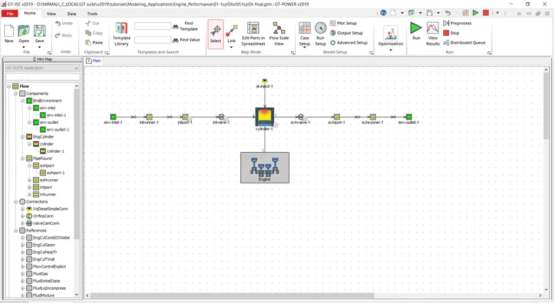
When we launch GT power software we can see a window as shown above. At the left top we see a GT-suite application menu which shows the various problems that can be modelling using this software.
The GT-power is categorised as follows
- Templates
- Objects
- Parts
The parameters available in GT-suite are
- Flow
- Mechanical
FOR EXAMPLE:
The basic subdivision of parameters are,
- Components
Under components
The templates available are,
- EndEnvironment
Objects under this template are,
- Inlet
- Outlet
The parts are available under these objects.
- Inlet-1
- Outlet-1
- EngCylinder
- PipeRound
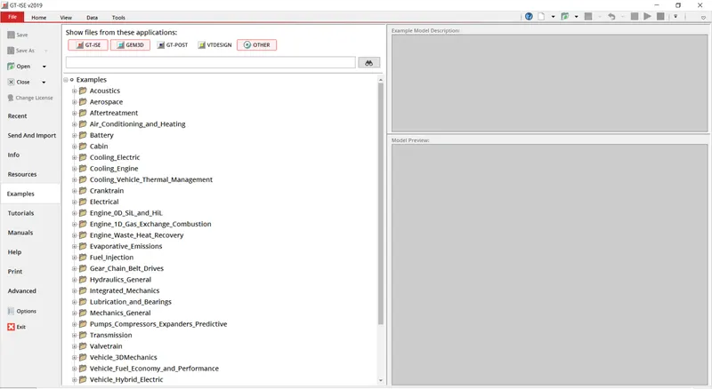
EXAMPLES:
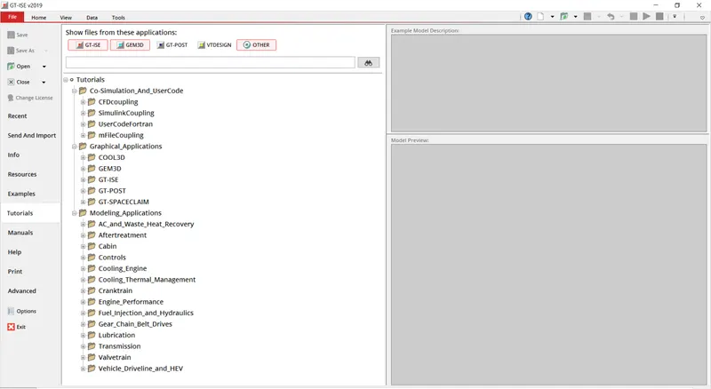
TUTORIALS:
DIFFERENT MODULES OF GT-POWER:
- Aerospace
- Engine performance
- Transmission
- After treatment
- Acoustics
- Cabin
- Battery
- Lubrication
- Control system
- Valve train
- Mechanics general
- Fuel injection
- Gear chain and belt drives
- HVAC
- Cooling engine
2. Locate following settings:
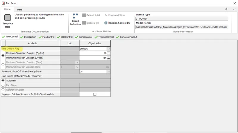
TIME CONTROL FLAG:
The feature can be accesed from run setup > time control.
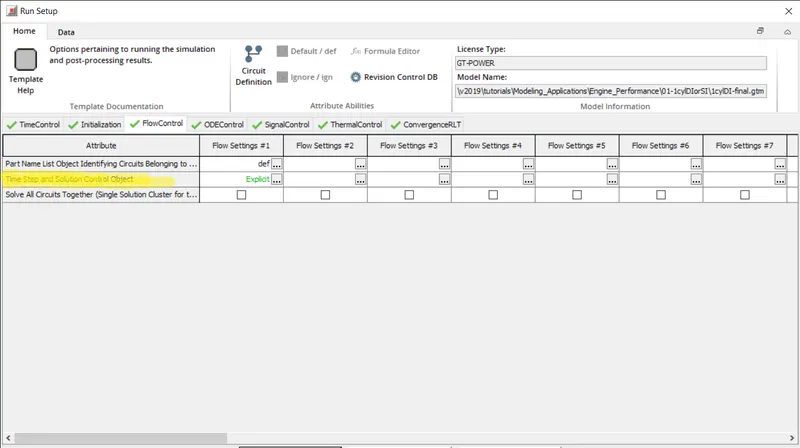
TIME STEP AND SOLUTION CONTROL:
Go to run setup > flow control > time step and solution control
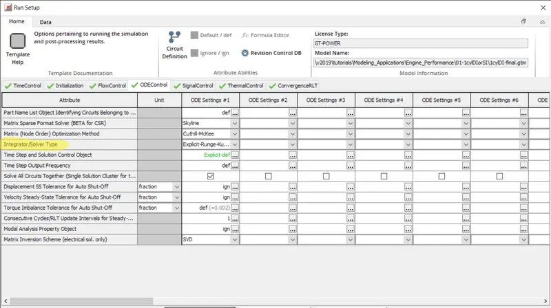
INTEGRATOR / SOLVER TYPE:
Go to run ssetup > ODEControl > integrator/solver type
3. Explore intercooler tutorial and note down all settings of:
INTERCOOLER TUTORIAL:
RUN SETUP:
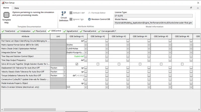
Under run setup there are various tab like Time control, initialisation, flow control, ODEcontrol, signal control, thermal control and convergeRLT.
From these tabs the parameters that has to be changed can be done.
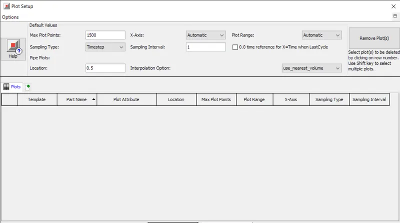
PLOT SETUP:
OUTPUT SETUP:
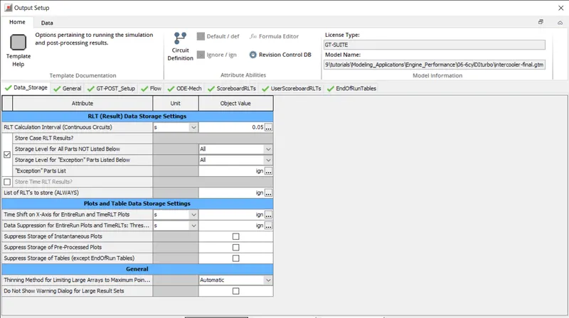
Under output setup the data storage, general, GT-post setup, flow, ODE mech, scoreboard RLT, user scoreboard RLT and end run table tabs are available.
These tabs can be used to define the parameters under output setup.
ADVANCED SETUP:
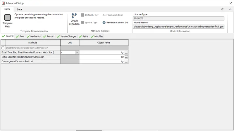
Advanced setup also contains various tabs and the parameters under these can be changed according to the user needs.
4. Problem:
CAC MODEL:
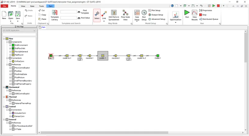
The CAC model can be explored by going to tutorials > modelling applications > engine performance > 6cylDiturbo
INPUTS:
INLET:
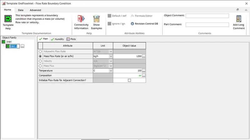
The mass flow rate and temperature are defined as 1200kg/hr and 100 c respectively.
COOLER:
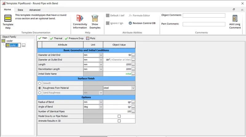
The diameter is defined as 50mm and the length as 1000 mm respectively.
OUTLET:
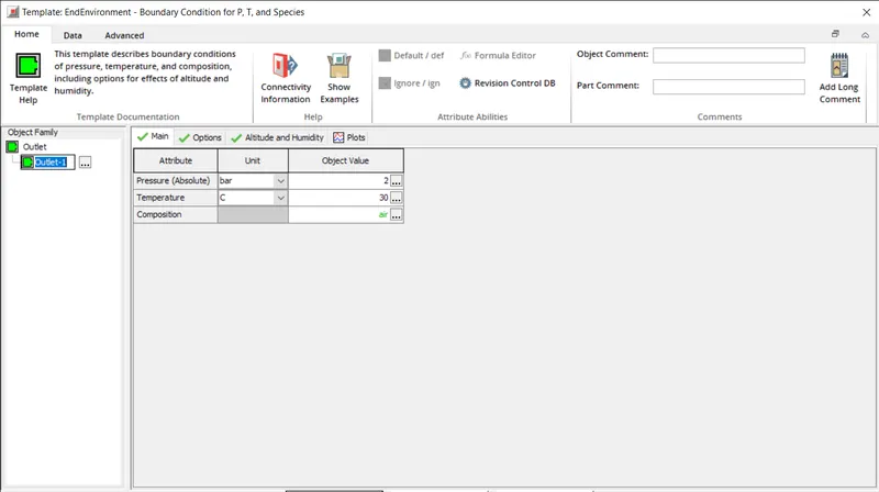
At outlet the pressure is 2 bar and 30 c is defined.
RESULTS:
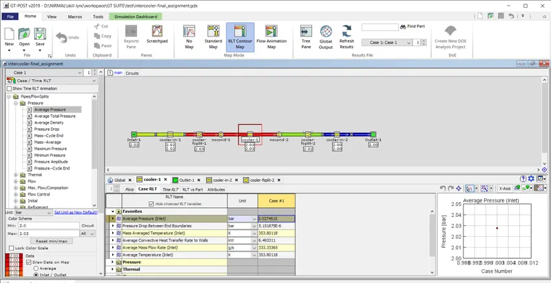
Pressure drop between boundaries = 5.151875e-6 Bar
Average heat transfer rate = 6.493311 KW