Week 1: Channel flow simulation using CONVERGE CFD
OBEJECTIVE
For this challenge, we will be setting up a channel flow tutorial.
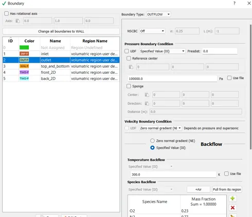
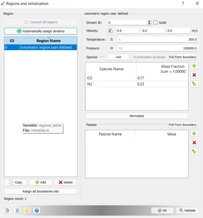
2. As you watch these videos, setup the case in CONVERGE
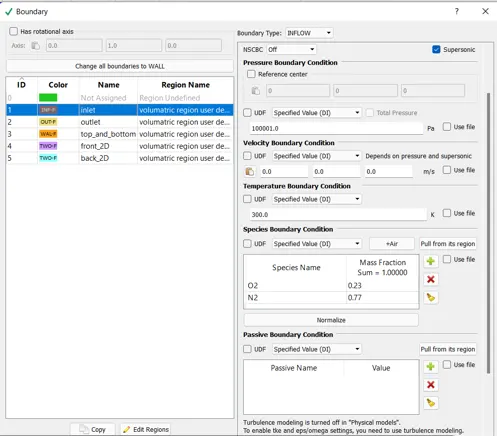
3. Make sure the inlet pressure and initial pressure are the same.
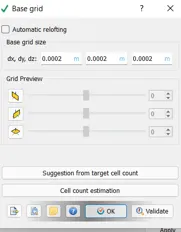
4. Once you have the base setup ready, run the case for three different base mesh sizes
i.e You need to run 3 simulations and compare the results between all the 3 simulations.
3 different base mesh sizes are,
- dx = 2e-4m, dy = 2e-4m, dz = 2e-4m
- dx = 1.5e-4m, dy = 1.5e-4m, dz = 1.5e-4m
- dx = 1.0e-4m, dy = 1.0e-4m, dz = 1.0e-4m
Before picking up the stimulation download access software after the prepare for simulation and post processing
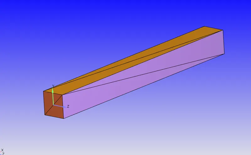
initially open converge studio and create gometry for channel Go to geometry create shape box and specify the centre and next geometry
About adding of the geometry go to options selected first normal after selecting the surface normal the normal are wanting towards the up for direction so what do is select any of the triangle and pick on them now the normal changes to the in the inward
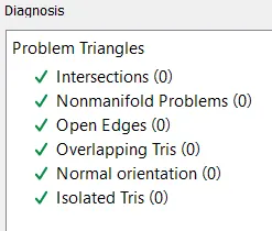
Next process is to dignosis the geomotry if any error in the geomotry nothing like a valadation
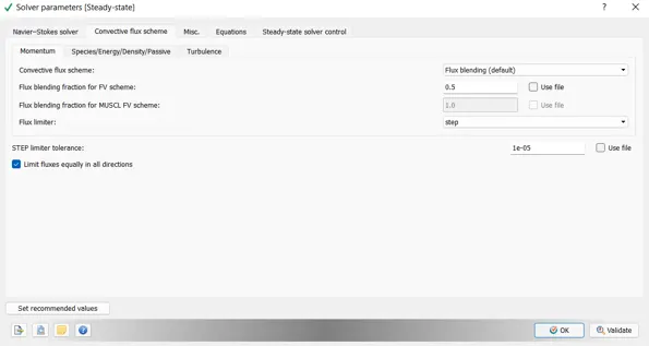
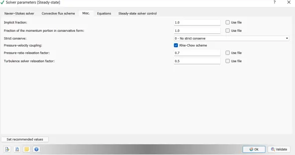
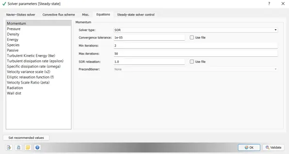
After the dignosis the next step is to case set up
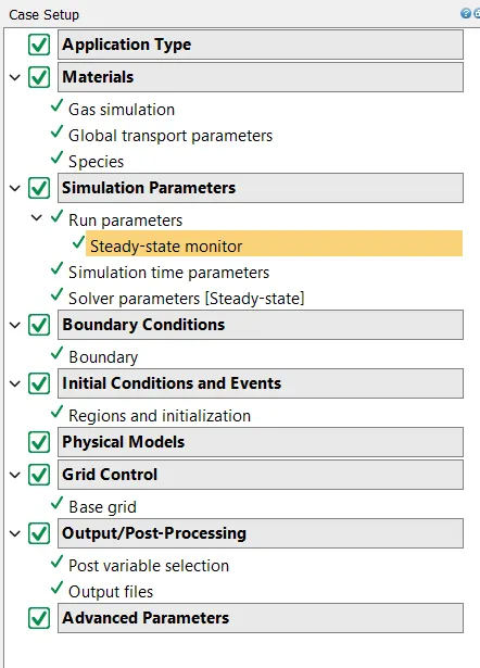
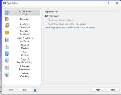
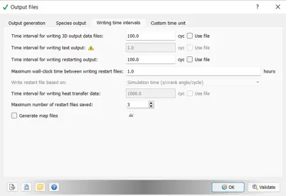
The below images shows the how to do case set up
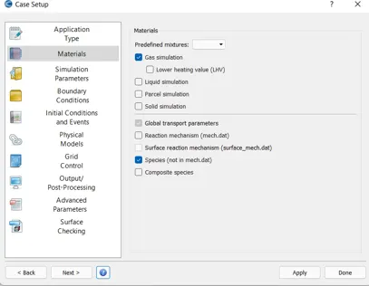
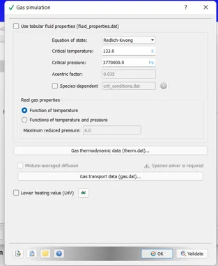
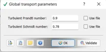
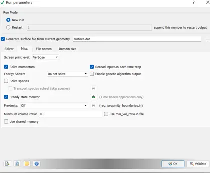
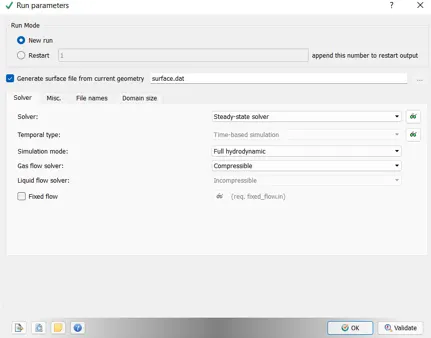
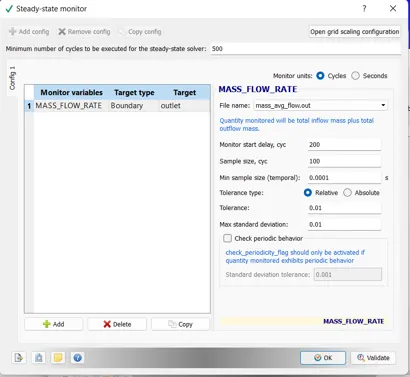
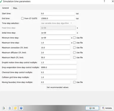
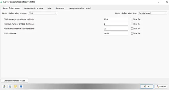
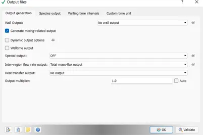
Cretae a folder and export all the file to post process
Run with the cigwin command before copy the slover and mpi files to folder
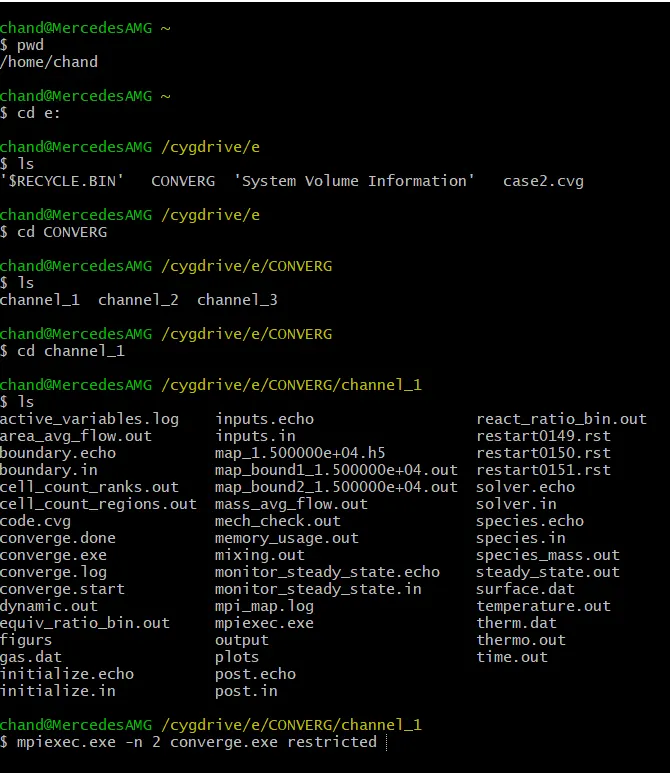
After the complation of run we must post process the files to run the simualation on paraview
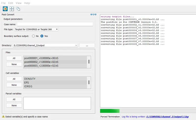
Open the paraview and open ._vtm group file to make the simulation
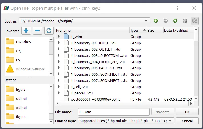
Check the mesh and run the simulation and see the velocity temprature pressure etc
CONCLUSION
It is observed that, velocity in the initial case is highest but as the mesh is coarse it is generally not preffered to be accurate. In the next two cases it calculated more accurately.
• The pressure obtained in all the cases remains constant. This is because both inlet and outlet are provided with constrained boundary conditions.
• Mass Flow Rate at the outlets for the refined cases are almost same.When both inlets and outlets are compared we can observe a positive flow and a negative flow.
. As the mesh becomes finer, the velocity profile obtained is also much clear compared to other two cases.
• Hence, as the grid size increases the results obtained are much clear and accurate.
Links for the animation.
https://www.youtube.com/watch?v=2Cdnzvnz2i8
https://www.youtube.com/watch?v=-R9Eje1JVAw