Week 1: Channel flow simulation using CONVERGE CFD
AIM:
To set up a channel flow simulation in converge studio.
OBJECTIVE:
In this simulation, we are going to run three different sizes of mesh to understand the physics behind the size of the mesh.
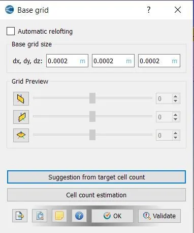
- dx = 2e-4m, dy = 2e-4m, dz = 2e-4m
- dx = 1.5e-4m, dy = 1.5e-4m, dz = 1.5e-4m
- dx = 1.2e-4m, dy = 1.2e-4m, dz = 1.2e-4m
PROCEDURE:
1.First, we need to open the converge studio and we need to create the geometry.
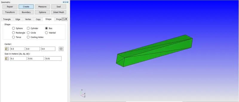
- In the geometry option, we need to click on create and go with the option shape and we need to give the dimension for the channel deisgn.
2. Now we need to check the normal is pointed towards the fluid region or not
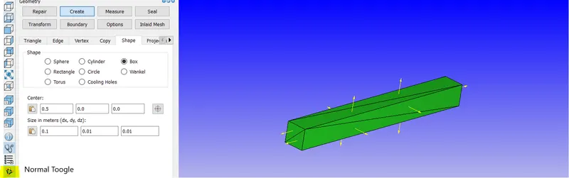
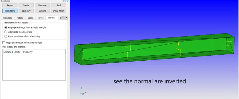
- Normal should be pointed towards the fluid region so for changing the normal we need to go to the Transform option and select normal.
- After selecting normal we need to select any one triangle and click apply the normal will be inverted.
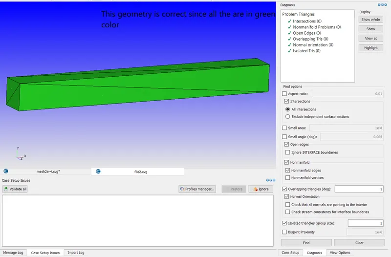
3. Now we need to check the geometry using the diagnosis option or use the short cut option ctrl+D
4. Now we are going to create a boundary for the geometry for creating we can use the boundary option
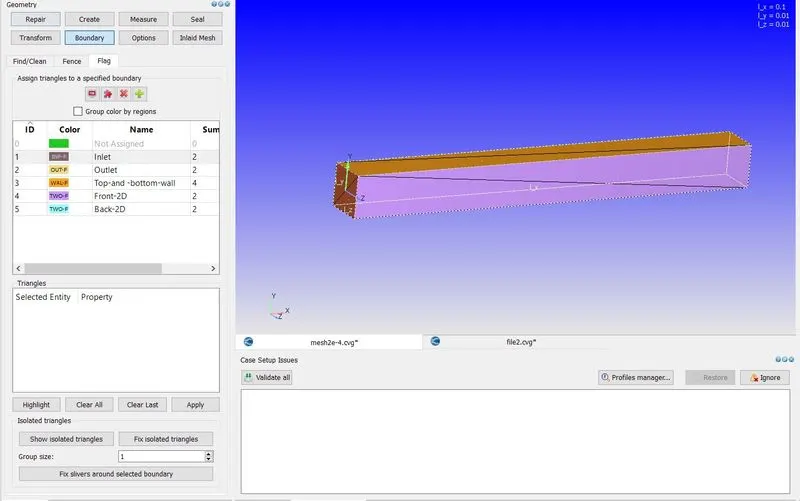
- Now we need to assign boundaries for each side by selecting the triangles.
5. Now we need to set up the case for simulation using case step option
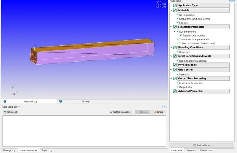
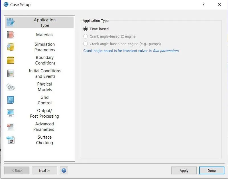
- In application type, we need to select time base option
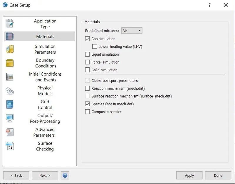
- In the material option, we need to select air
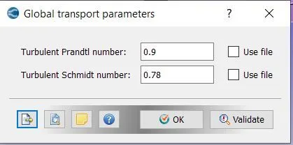
- we don't need to change anything in Global Transport parameters
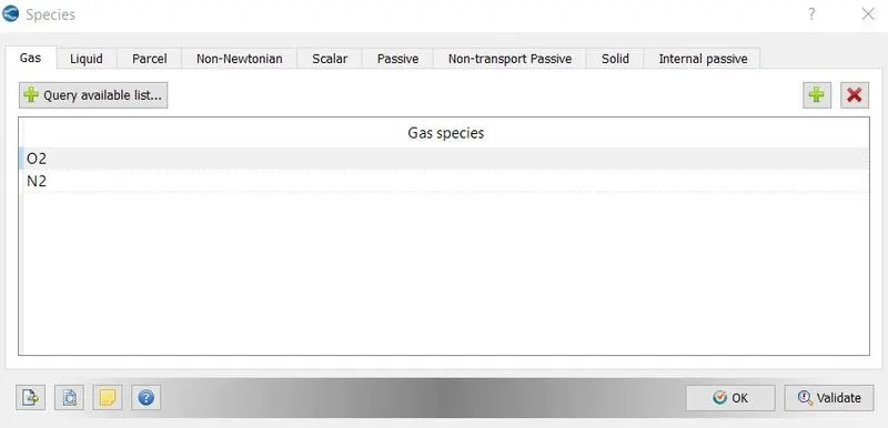
- In the species option, we need to select N2 and O2 because air is our mixture that will flow inside the channel
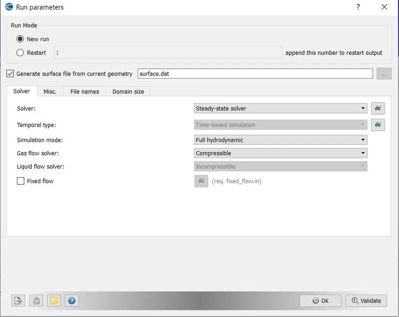
- In simulation parameters, we need to click on run parameters and we need to change solver as steady state solver since we are going to run the steady-state simulation
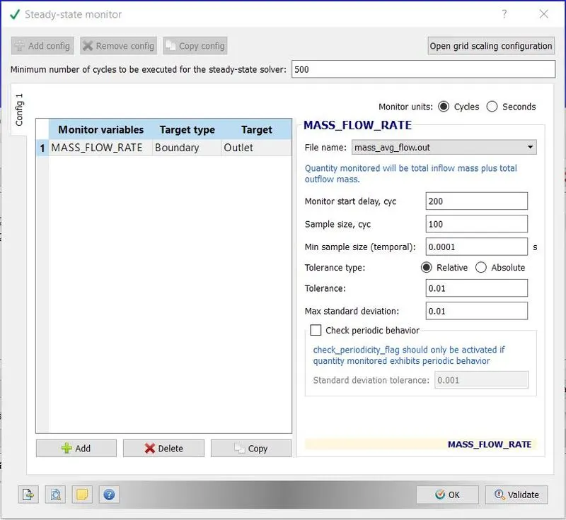
- The steady-state monitor will help to monitor the solution and the simulation also ends faster as it reaches the convergence point it stops the simulation.
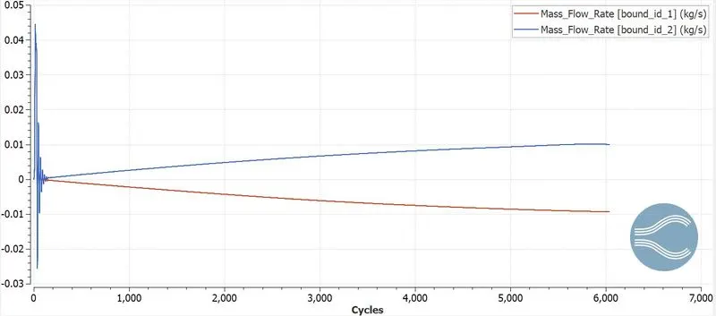
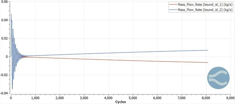
- Here we are going to monitor the mass flow rate at the outlet.
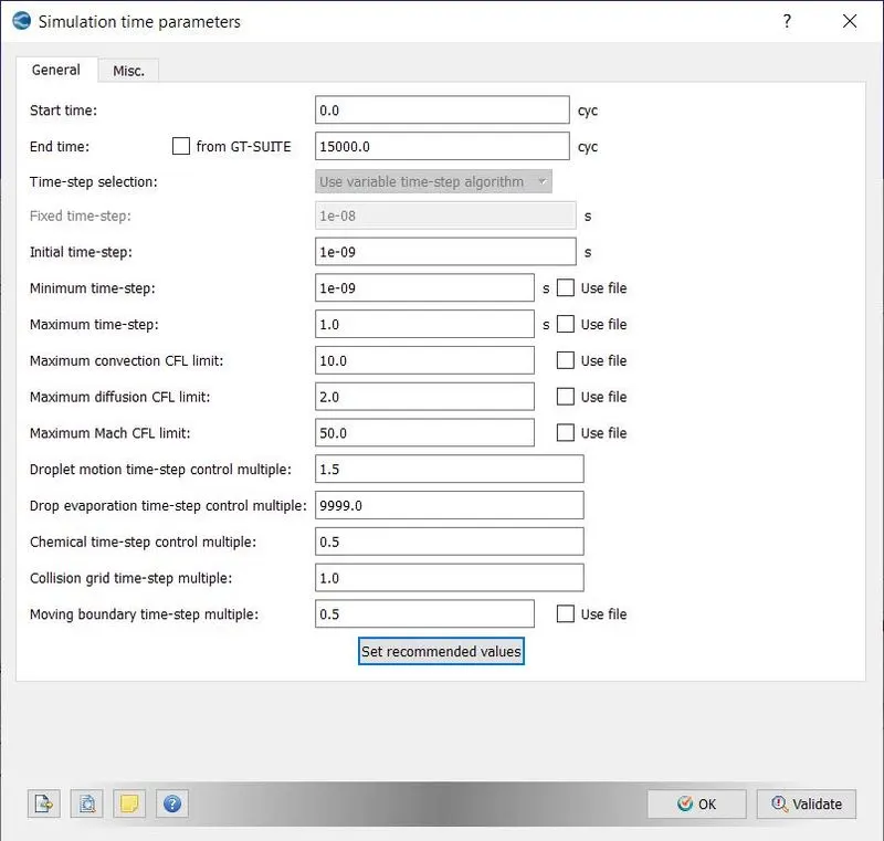
- In simulation parameters, we will set up the number of cycles, initial time step, minimum time step, maximum time step, and more
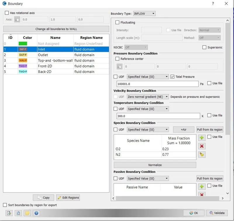
- In boundary conditions, we need to assign the initial values for simulation
- For inlet, we are using 100001.0 pa
- For outlet, we are using 100000.0 pa
- Top and bottom wall are consider as wall and we describe as no slip condition
- Here both front and back wall is consider as 2D
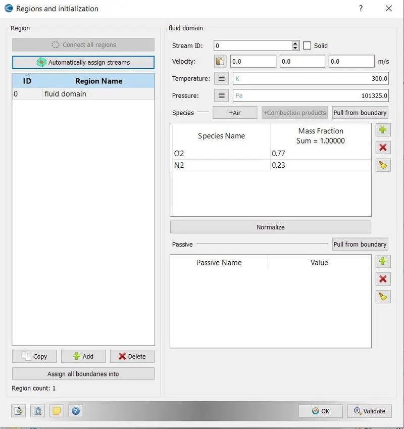
- In initialization, we are going to create fluid regions like fluid domain
- In base grid option we will be given our mesh size
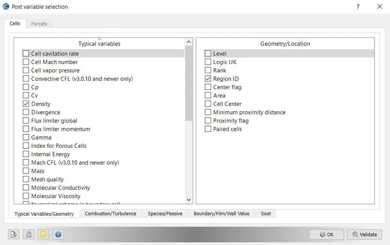
- In post variable selection we will be selecting the outputs that we need for the problem and simulation
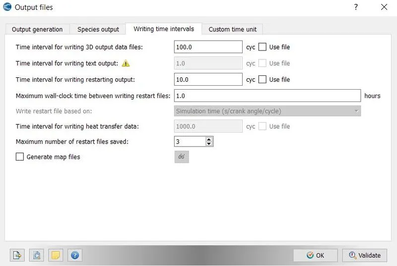
- In output files, we can give time interval for writing 3D outputs and time intervals for writing the restart output files
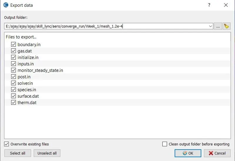
- After finishing setting up the case we need to Export the input files using export option
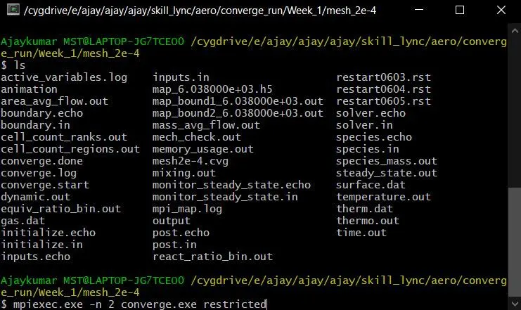
- Now open the Cygwin terminal and navigate to the folder where you export the input files
- Use mpiexec.exe -n 2 converge.exe restricted command to run the simulation
- After the simulation is finished we need to convert the output files as ParaView format
- Now again open Cygwin and navigate to the folder which has output
- mpiexex.exe -n 2 post_convert.exe_30_msmpi_64.exe using this command we can convert the output files as paraview format
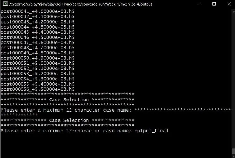
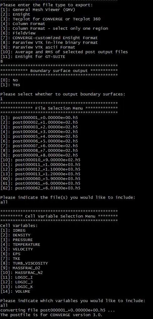
The above procedure is the same for the three case study only mesh size is going to differ.
Results:
case 1 mesh 2e-4:
Mesh generation:
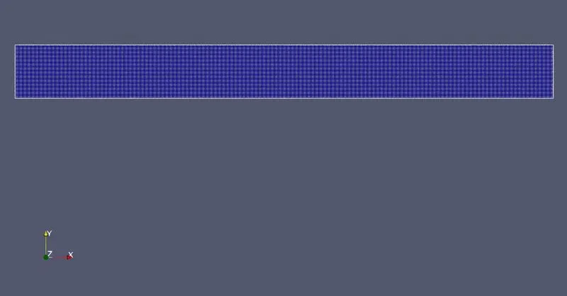
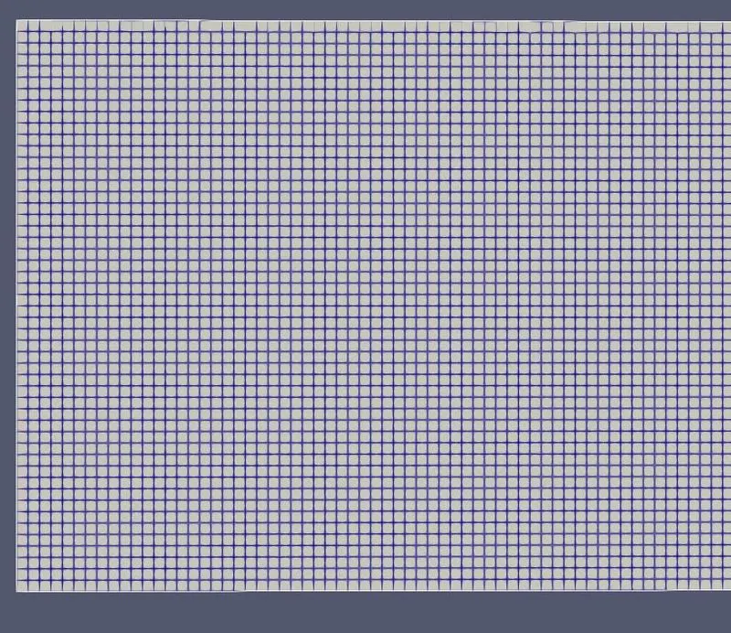
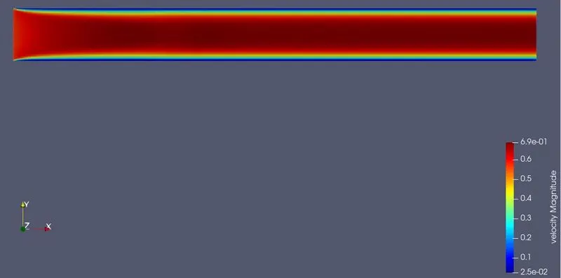
Velocity Contour:
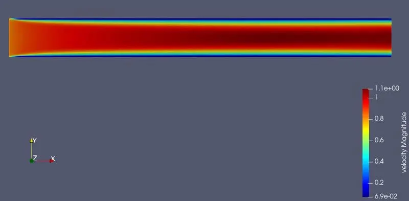
Animation for Velocity Contour:
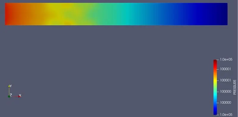
Pressure Contour:
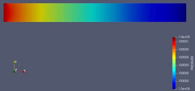
Animation for Pressure Contour:
Mass Flow Rate Plot:
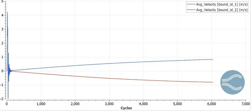
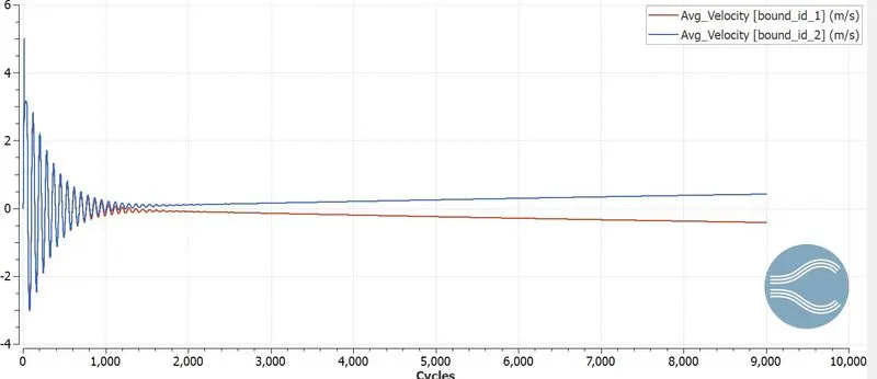
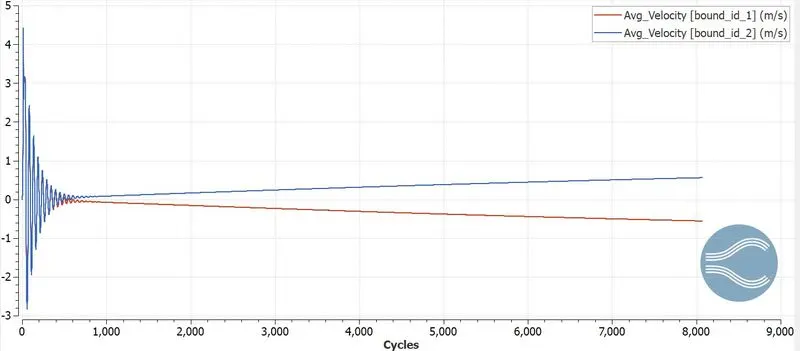
Average Velocity Plot:
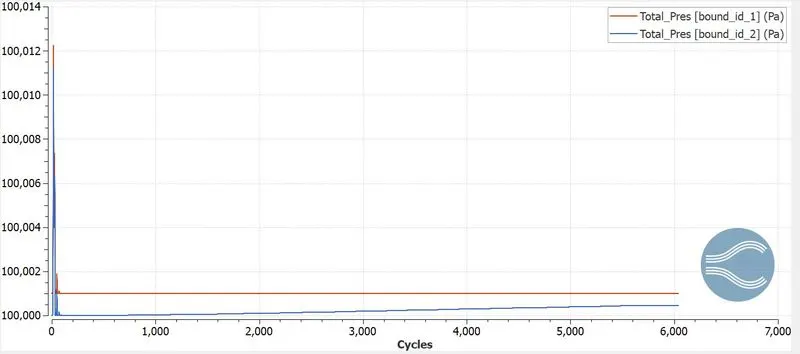
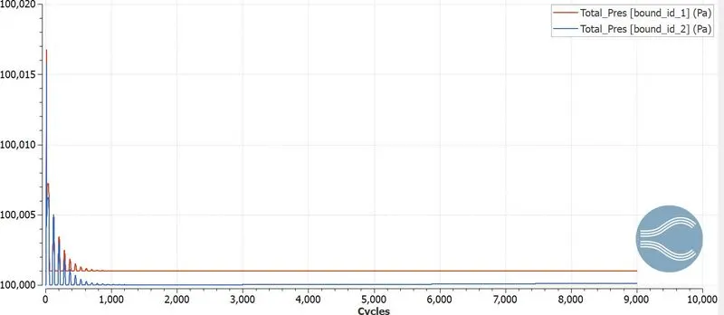
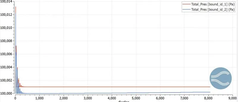
Total Pressure Plot:
Case 2 mesh size 1.5e-4:
Mesh Generation:


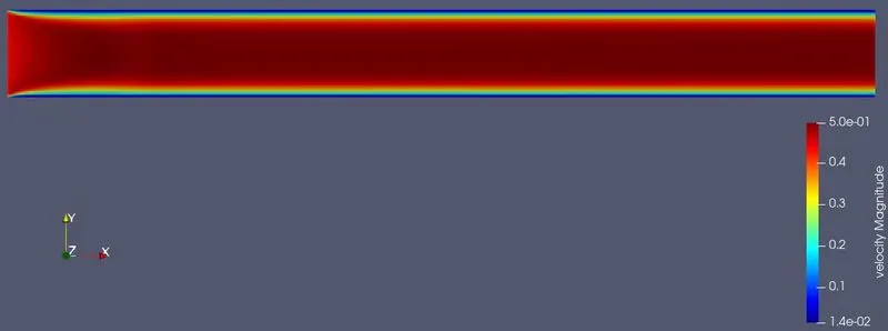
Velocity Contour:
Animation for Velocity Contour:
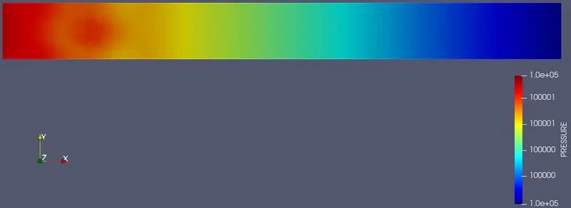
Pressure Contour:
Animation for Pressure Contour:
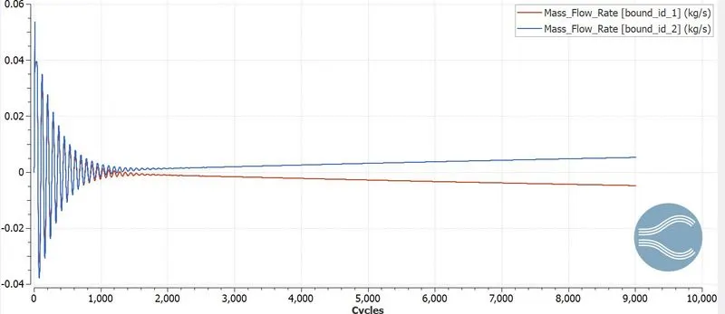
Mass Flow Rate Plot:
Average Velocity Plot:
Total Pressure Plot:
Case 3 mesh size 1.2e-4:
Mesh Generation :


Velocity Contour:
Animation for Velocity Contour:
Pressure Contour:
Animation for Pressure Contour:
Mass Flow Rate Plot:
Average Velocity Plot:
Total Pressure Plot:
CONCLUSION:
- While decreasing the mesh size we can see that the time for solving the problem is also increased and the results are also very accurate.
- We can compare mesh size 2e-5 and mesh size 1.2e-4 the results in the mesh size 2e-4 are inaccurate but the results in mesh 1.2e-4 are accurate.
- Mass flow rate doesn't change for all three cases since the fluid domain is the same there is no change.