Week 1: Channel flow simulation using CONVERGE CFD
Objective:
- Channel flow simulation.
-
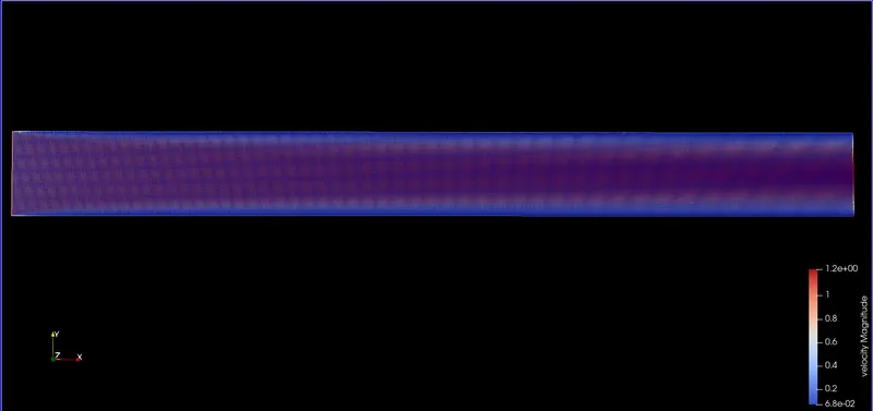
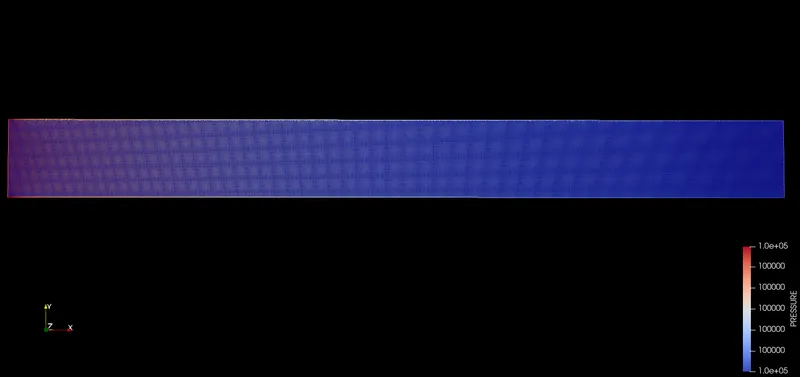
Velocity and pressure contours for all the 3 base mesh size
-
Show mesh (i.e surface with edges) for the 3 base mesh sizes
-
Plots for velocity, pressure,mass flow rate and total cell count for all 3 base mesh sizes.
Introduction:
Channel flow is an internal flow in which the confining walls change the hydrodynamic structure of the flow from an arbitrary state at the channel inlet to a certain state at the outlet. The simplest illustration of internal flow is a laminar flow in a circular tube while a turbulent flow in the rotor of a centrifugal compressor is an example of the most intricately-shaped internal flow.Engineering devices employ channels with cross-sections of various geometrical shapes.
Geometry:
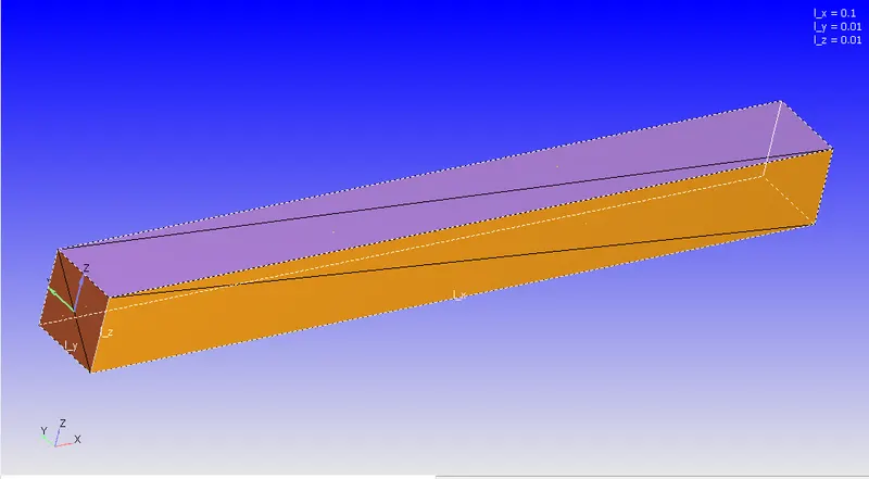
The stl file of the channel is imported into converge studio. The steps that are taken care of in preparing the geometry are:
- Running diagnosis to check if there are any open edges or faces.
- Checking the orientation of the normals. The normals will be such that , there orientation is facing towards the flow of fluid.
Boundary flagging:
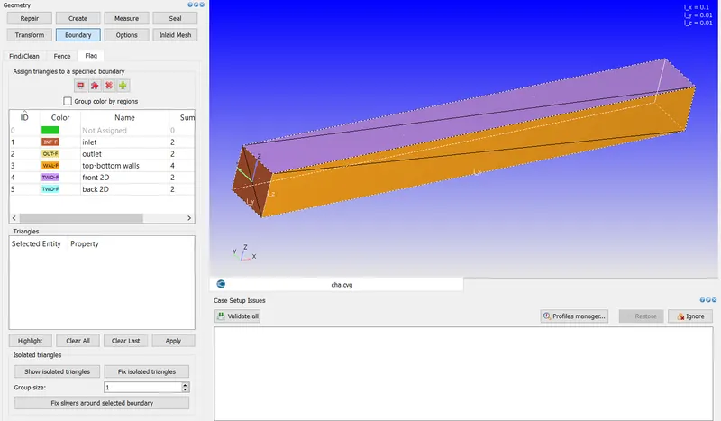
The boundaries are flagged . The converge studio basically uses triangular blocks to create the geometry. So by selecing the triangles, boundaries are flagged.
- Inlet
- Outlet
- Front2d
- back2D
- top and bottom walls
Case set up:
- Application type:
The application type is time based , since this donot involves any IC engine analysis.
- Materials :
The preffered material selection is air. Gas simulation is checked. The species are O2 and N2.
The global transport parameters are left as selected by default by converge.
- Simulation parameters:
The simulation parameters are :
Compressible flow and full hydrodynamic. Steady state solver is used.
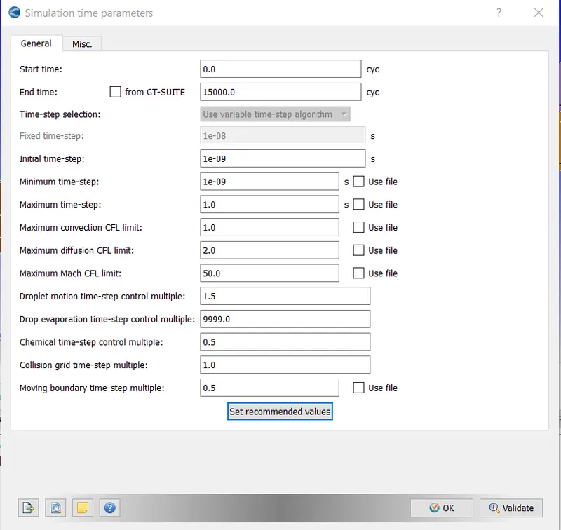
The simulation time parameters are :
Number of cycles = 15000, minimum time step size and initial time step size is 1e-9 . The maximum convection diffusion CFL limit is 1.
The Navier stokes solver scheme is PISO.
Boundary conditions:
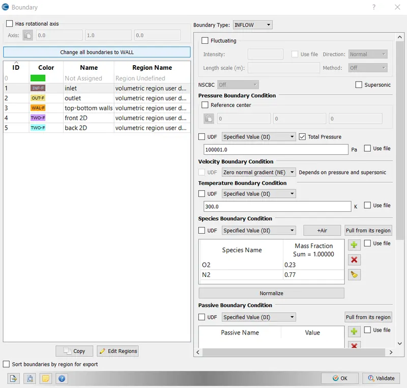
- Inlet :
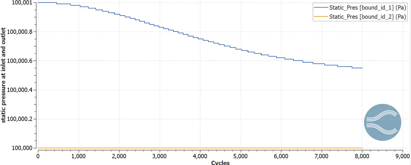
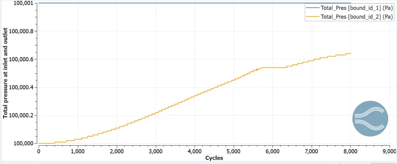
The inlet is inflow type. The total pressure at the inlet is 100001 Pa. The secies mass fractio are 0.23 for oxygen and 0.77 for Nitrogen. Temperature is set at 300K.
- Outlet:
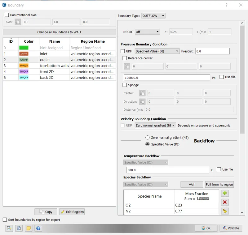
This is a outflow boundary . The gauge pressure at outlet is 100000 Pa. The species mass fraction for backflow are 0.23 for O2 and 0.77 for Niitrogen
- Front 2D and back2D :
Both are assigned two dimensional boundary conditions.
- Top and bottom wall:
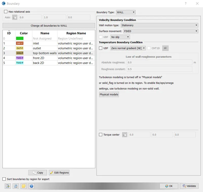
Wall boundary condition is assigned. Stationary wall is opted for. No slip condition is enabled for the walls.
- Regions and initialization:
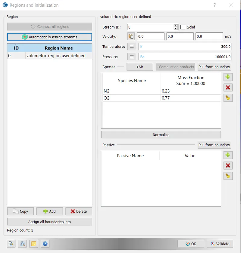
The region created with oxygen mass fraction as 0.77 and Nitrogen mass fraction as 0.23. Every boundary is assigned to this created region.
Grid size :
Three grid sizes are analysed. No embedding is done.
- results:
Grid size : dx=2e-4 m; dy=2e-4 m;dz=2e-4 m
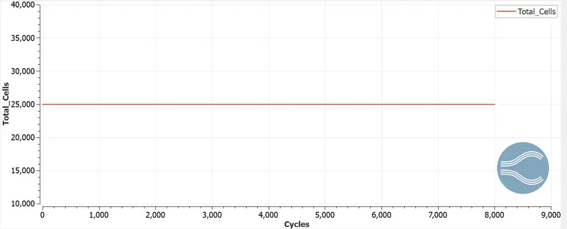
Number of cells = 25000
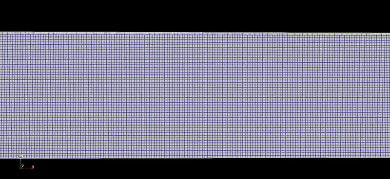
- Surface with edges:
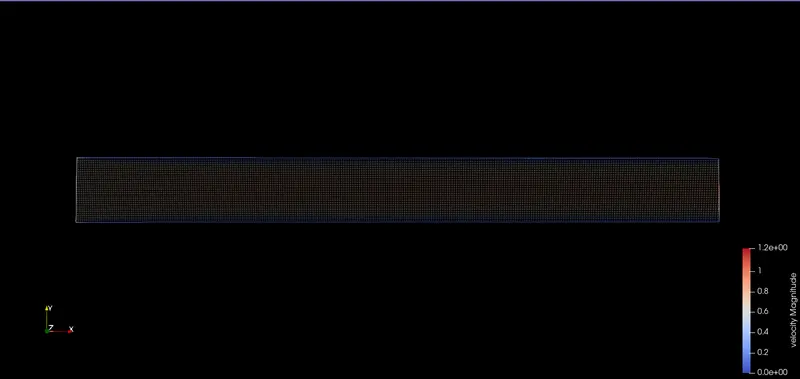
- velocity contour:
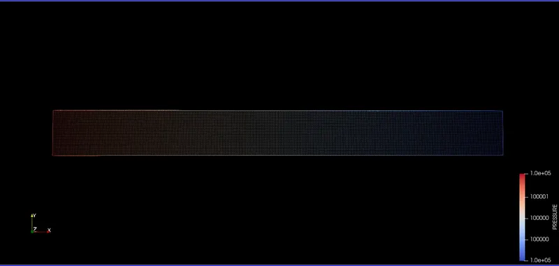
- Pressure contour:
- Plots:
- Average velocity at inlet and outlet:
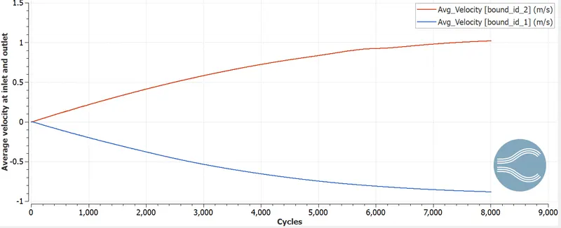
The velocity profile takes up a parabolic profile with the number of cycles.
- Static pressure at inlet and outlet:
- Total pressure at inlet and outlet:
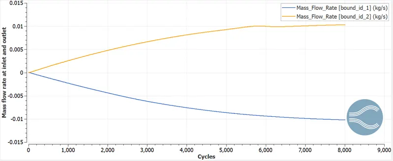
- Mass flow rate at inlet and outlet:
- Total number of cells:
- Total number of cycles:
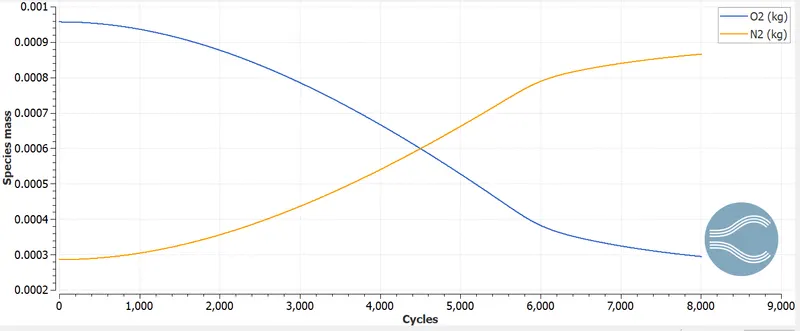
- Species mass :
Grid size: dx=1e-4 m; dy=1e-4 m; dz=1e-4 m
Number of cells = 100000
- Surface with edges:
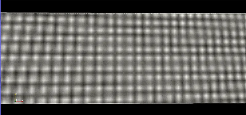
- Velocity contour:
- Pressure contour:
- Plots:
- Average velocity at inlet and outlet:
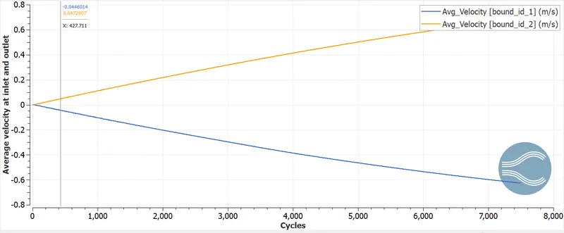
The velocity profile takes up a parabolic profile with cycles.
- Static pressure at inlet and outlet:
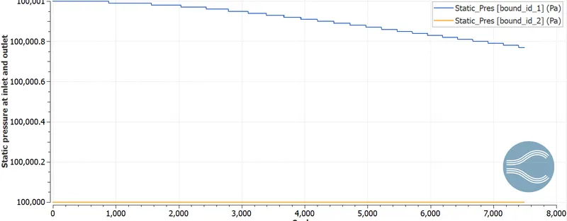
- Total pressure at inlet and outlet:
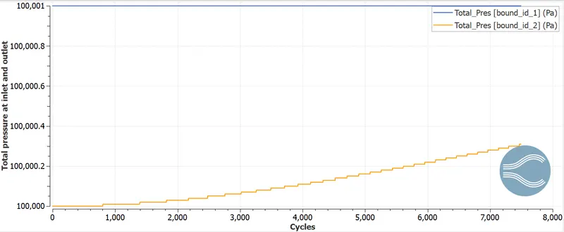
- Mass flow rate at inlet and outlet:
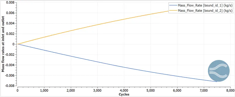
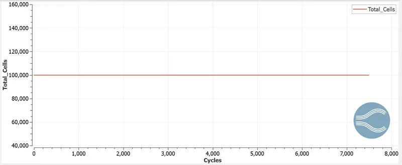
- Total number of cells:
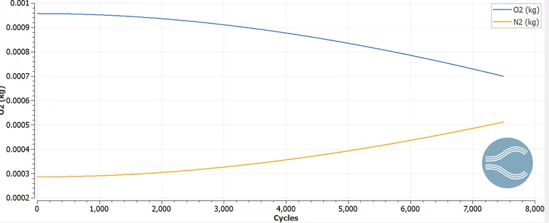
- Species mass :
Animation video link of the channel flow simulation with grid size 2e-4 meters is https://youtu.be/ctE6_KWlObs
Animation video link of the channel flow simulation with grid size 1e-4 meters is https://youtu.be/yODB82P7Xw8
Conclusion:
- This is a laminar flow analysis, since the Reynolds number is very less.
- The velocity profile is parabolic .