Week 1: Channel flow simulation using CONVERGE CFD
Aim:
1. To setup the case in CONVERGE
2. To run the case for three different base mesh sizes
3. To obtain Velocity and pressure contours for all the 3 base mesh sizes
4. To Show mesh (i.e surface with edges) for the 3 base mesh sizes
5. To Plots for velocity, pressure,mass flow rate and total cell count for all 3 base mesh sizes.
i.e You need to run 3 simulations and compare the results between all the 3 simulations.
Conditions:
1.The inlet pressure and initial pressure are the same.
3 different base mesh sizes are,
- dx = 2e-4m, dy = 2e-4m, dz = 2e-4m
- dx = 1.5e-4m, dy = 1.5e-4m, dz = 1.5e-4m
- dx = 1.0e-4m, dy = 1.0e-4m, dz = 1.0e-4m (If this is too much for your PC, use 1.2e-4m)
Initial Case setup:
- Open converge and create the channel with the dimension under box creation.
- Center : 0.05 0.0 0.0
- Size : 0.1 0.01 0.01
- Next would be boundary creation.
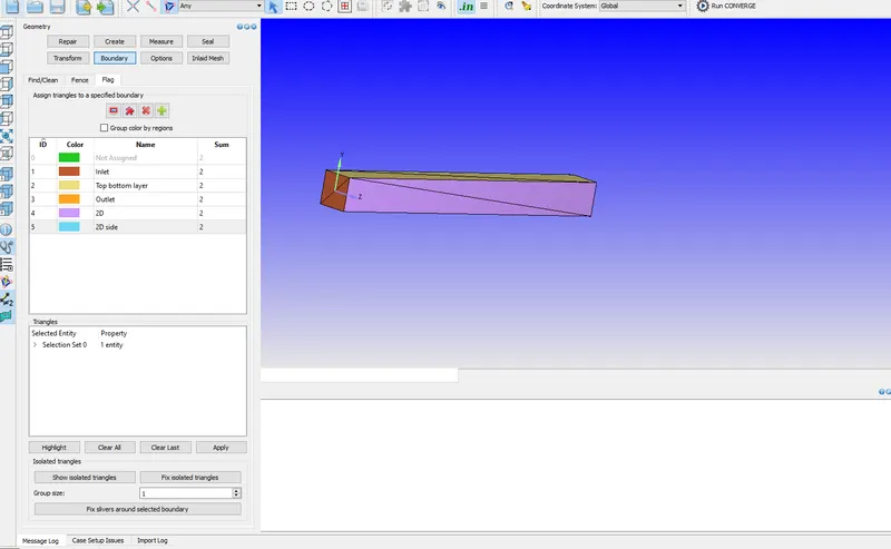
- Boundary --->flag---->add the boundary and name them.
- Select the triangles and update them.
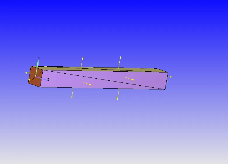
- Next choose case set up option and update each case individually.
- Normal should point towards the flow.
- Transform->Normal->Select the triangle with inappropriate normal->apply.
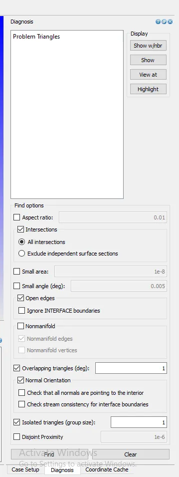
- Diagnosis tools checks the geometry for errors.
- Check and clear the following options.
- Intersection
- Open edges
- Non-manifold
- Non-manifold edges
- Normal Orientation
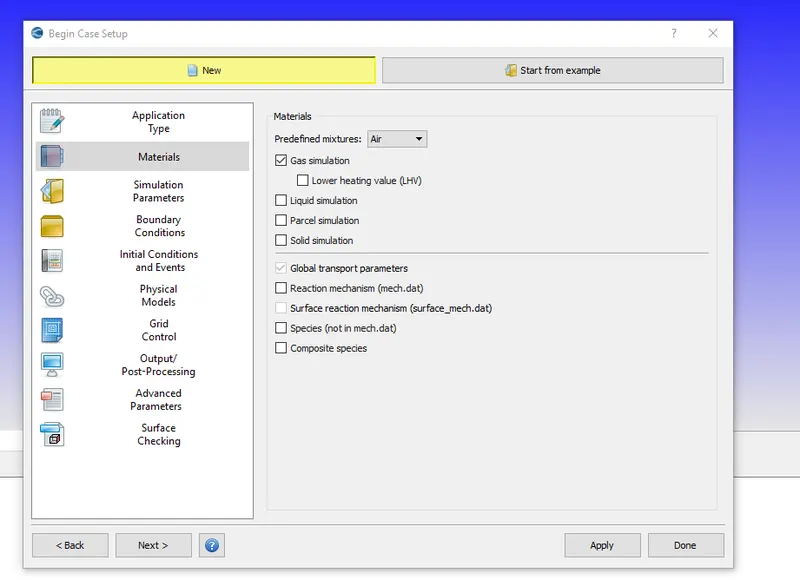
- Materials:
- Predefined mixture is Air. Select and click ok.
- No reaction mechanism->Apply,.
- Simulation parameters:
- Start with time,limits to be declared.
- and the rest remains the same.
- declare the boundary with intensity of 0.02 and the pressure range of 100001.0 for the air.
- Similarlly declare and specify for the inlet oputlet and rest.
- Temperature specified value is 300.0k.
- No-slip condition
- Physical models:
- Uncheck the box and choose only turbulence model-done
- Regions and initialization:
- Give ID and define theregion name.
- Base grid:
- dx,dy,dz remians 0.001 and next change with 0.004
- Post variable selection:
- Declare the species-mass fraction-N2 and O2 add then-ok
- Output files: Time interval for writing 3D output data files 100 cycle
- File -export-export input and output files
- Coverge support files-converge runs-support cases-create new folder and name as channel flow-selelct-ok
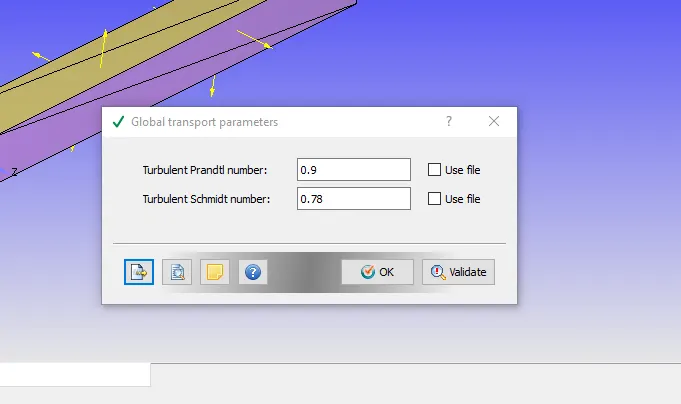
- Files get exported to the folder.
- NOTE:
- Run parameters: Steady state(Time in cycle)
Transient state(Time in sec)
Crank angle state(Time in Crank angle)
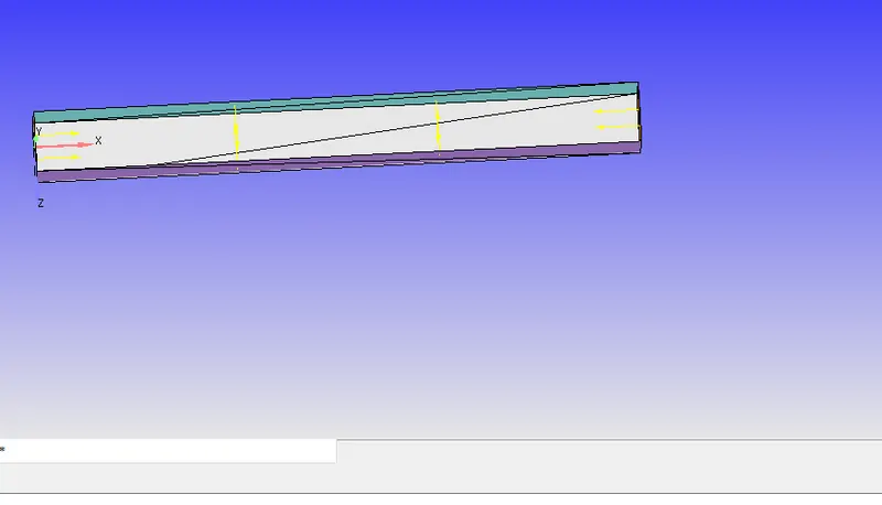
- MIsc:
- Use shared memory uncheck this box and check the steady state monitor-ok
- Steady state monitor is used when you want to monitor pressure,temperature, velocity and add choose from the drop down option.
- Min no of cycles 5000
- Average temperature:
- Monitor start:0
- sample size:1000
- Min sample size:0.0001
- Tolerance type:Relative
- Max std der:0.01
- Tolerance:0.01
NOTE: 1.Always set preconditioner to none,because it will throw an error while running the simulation.
2.If the sample size is within the tolerance limit then the system gets converged and crossed the minimum cycle it gets terminated.
- Solver parameters [steady state]:
- Navier stokes solver type is density based and set the equation under preconditioner to none.
RUNNING THE CHANNEL FLOW IN CYGWIN:
- msmpi.exe is the library that converge uses to run the simualtion parallel in windows.
- Install and use CYGWIn and vim is the editor.
- Navigate to the directory and run the file
NOTE: command not found ,type the command-folder-converge-copy-license- paste to the channel flow folder.
SIMULATION:
Go back to cygwin and recall the same command and enter.
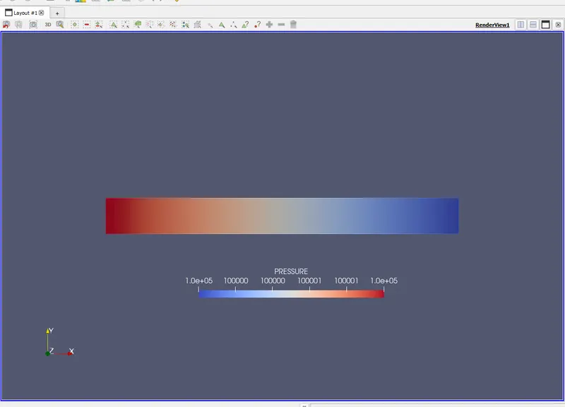
In paraview, Choose the file,slice, z-normal,show plane,apply.
The process shows up and then time parameter to the max limit runs.
RESULT/OUTPUT:
Mesh is carried out and results for the same is obtained and attached.
Animation for the channel flow through converge process is obtained.