Week 1 Challenge
1)
Access the Staad software and locate the share feature on the introductory screen.
Once you have found the share button, click on it and choose the option to send an email.
Next, search for the .std file on your computer and proceed to send it
2)
Concrete, steel, aluminum, timber, and composite sections.
-
Analytical Model: It focuses on the analysis and design aspects of the structure.
-
Physical Model: It is used for visualizing and understanding the physical behavior of the structure.
-
Building Planner Model: This model is specifically designed for building planning and layout purposes. It helps in organizing and arranging the various components and spaces within a building, considering factors such as functionality, aesthetics, and efficiency
5)
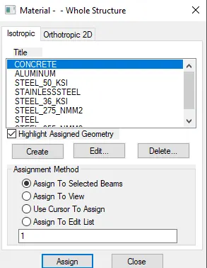
To assign a material property to your model in STAAD, follow these steps:
- Go to the properties panel.
- Click on "Materials" to access the material settings.
- From the list of available materials, select your desired material, such as concrete, steel, aluminum, stainless steel, etc.
- Next, choose the assignment method based on your preference. You may have options like using the cursor or assigning it to a specific view.
- Once you have selected the assignment method, proceed to assign the material property to your model by clicking on the appropriate radio button or button provided.
By following these steps, you will be able to assign the chosen material property to your model in STAAD.
6)
The six Design parameter involved in RCC design are as below;
- Clear cover
- FC compressie strength of concrete
- FY Tensile Strength of steel
- Max main Dia of bar
- Code of practice
- End conrete design
7)
In STAAD Pro, there are various cursor types available for different purposes. Here is a list of cursor types you can use:
-
Nodes cursor: This cursor allows you to select and manipulate nodes in your model.
-
Plates cursor: With this cursor, you can select and modify plate elements in your model, such as slabs or floor plates.
-
Beams cursor: The beams cursor enables you to select and edit beam elements, which represent structural members like columns or beams.
-
Plates and Solid cursor: This cursor allows you to select and work with both plate elements and solid elements simultaneously.
-
Loads cursor: The loads cursor is used for selecting and applying loads or load cases to specific elements in your model.
-
Solids cursor: With the solids cursor, you can select and manipulate solid elements, which represent three-dimensional objects like blocks or volumes.
-
Physical Member cursor: This cursor is specifically designed for selecting and modifying physical members in the model, which are used in physical modeling.
-
Geometry cursor: The geometry cursor enables you to select and modify geometric entities or shapes in your model, such as lines or arcs.
9)
To access different view options in STAAD Pro, follow these steps:
- Go to the "View" option in the ribbon menu at the top of the software interface.
- Click on the "View" option to expand the dropdown menu.
- In the expanded menu, you will find various view options, such as:
- Top view:
- Isometric view:
- Front view:
- Left view:
- Right view:
- Bottom view:
- Back view:
10)
To access the support commands in STAAD Pro, follow these steps:
- Go to the tool palette/command panel in the software interface.
- Look for the "Create Support" command and click on it to select it.
- After selecting the "Create Support" command, you will be presented with various options for different types of supports. These options include:
- Fixed support:
- Pin support:
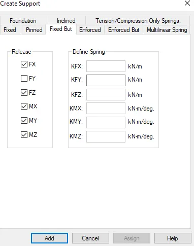
- Fixed but:
- Enforced but support:
- Cable support:
- Inclined support:
By selecting the desired view option from the "View" menu, you can change the perspective and orientation of the structure in the STAAD Pro software.
11)
The Design Brief Report (DBR) serves as a concise overview of a project, outlining its purpose, location, structural layout, construction methodology, quality assurance and quality control measures, and budget. Here are the five topics that should be included in creating a DBR:
-
Project Name and Location:
-
Structural Layout:
-
Construction Methodology:.
-
Quality Assurance and Quality Control:
-
Budget of the Project:
12)
It supports various materials such as steel, concrete, and timber, allowing users to assign different materials to individual members within a structure. These separate members are then coordinated and assembled to form the complete structure. STAAD.Pro facilitates the efficient modeling and design of structures.
13)
The structure systems available in STAAD Pro software are:
-
Space Frames: Space frames are three-dimensional truss-like structures that can span long distances without the need for intermediate supports.They are characterized by their lightweight and rigid nature, making them structurally efficient. Space frames are commonly used in applications where long spans and minimal support are required, such as stadiums, exhibition halls, and airport terminals
-
Plane Frames: Plane frames are two-dimensional structures composed of straight elements, such as beams and columns, interconnected by rigid or hinged connections.
-
Trusses: Trusses consist of triangular units formed by arranging structural members, such as beams and bars, to efficiently transfer loads in both compression and tension.
14)
The Design Brief Report (DBR) is indeed a project management document that contains essential information about the construction of a structure. It serves as a comprehensive report, providing minute details of the ongoing construction work. The DBR represents the final stage in defining the client's requirements for the construction project.
The report includes various crucial structural details that are relevant to the project. It typically covers the following aspects:
-
Description of the Client:
-
Site Information:
-
Special Requirements:
-
Technical Requirements:
-
Components Required:
-
Project Requirements:
-
Other Construction-Related Issues:
15)
The STAAD Pro software offers various types of analysis options to evaluate the behavior and response of structures. Some of the common analysis options available are:
-
Linear Elastic Analysis: It assumes that the structure behaves linearly under load, where the material properties remain constant.
-
P-Delta Analysis: It accounts for the second-order effects caused by the deflections in the structure under applied loads.
-
Buckling Analysis: Buckling analysis is used to assess the stability of structural members under compressive loads. It determines the critical buckling loads and modes of failure.
-
Pushover Analysis: Pushover analysis, also known as nonlinear static analysis, evaluates the behavior of a structure under gradually increasing lateral loads. Pushover analysis is particularly useful for seismic design and assessing the performance of structures under earthquake loads.
16)
Fixed Condition: In STAAD Pro software, the fixed condition refers to a boundary condition where all degrees of freedom, including horizontal, vertical, and rotational movements, are completely restrained or fixed. This means that the structure is unable to move or deform in any of these directions. The fixed condition is used when a member or support is rigidly connected to the ground or another structural element, and no relative movement or rotation is allowed.
Fixed-But Condition: The fixed-but condition in STAAD Pro software allows for customization of the end conditions of a member. Unlike the fixed condition, the fixed-but condition allows for some degree of freedom at the ends of the member. This means that certain degrees of freedom can be released or made flexible, while others remain fixed. This condition allows for more flexibility in modeling and analyzing the structure, as it allows for the consideration of partial restraints or supports at specific locations along the member.
17)
-
Open the STAAD Pro software and create a new model:
- Launch the STAAD Pro software and click on the "New" option available on the intro screen.
- Enter the project details and specify the location within your system.
- Click on "Create" to start a new project.
-
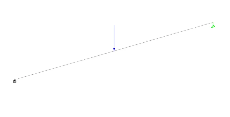
Draw the beam of the required span:
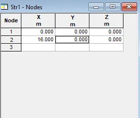
- Go to the "Geometry" tab and create the first node at X-0, Y-0, and Z-0 coordinates.
- Switch to the node cursor, select the created node, and copy it (Ctrl+C) and paste it (Ctrl+V).
- Specify the span length of 16 meters in the X-direction and hit enter.
- Use the "Add Beam" option to create a beam between the two nodes.
-
Assign support conditions:
- Go to the "Support" tab and add a fixed support to one node by selecting the node and assigning the fixed support condition.
- Create another node and assign a fixed-but support condition, releasing moments and horizontal restraints.
-
Assign properties and materials to the beam:
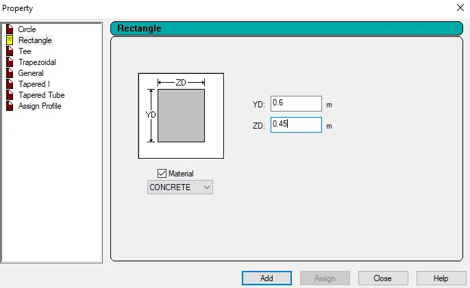
- Define the properties of the beam such as width and thickness.
- Assign the material properties to the beam, such as concrete.
-
Assign the proposed load:
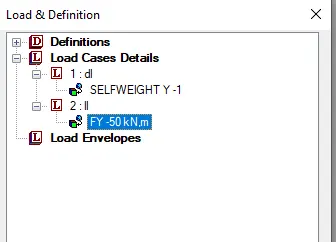
- Go to the "Loads" tab and create a member load with a global Y-direction load of -50kN.
- Specify the load distribution factors (d1 and d2) and apply the load to the selected beam.
-
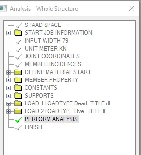
Run the analysis:
- Select the desired analysis method from the design and analysis panel.
- Run the analysis from the analysis and design panel.
- Wait for the analysis to complete and check for any errors or warnings.
-
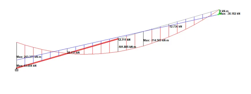
Draw SFD and BMD:
- Go to the post-processing mode and select the load cases to view the analysis results.
- Apply the selected load cases and view the shear force diagram (SFD) and bending moment diagram (BMD) for the beam.
- Annotate the diagrams to display the values along with the diagrams.