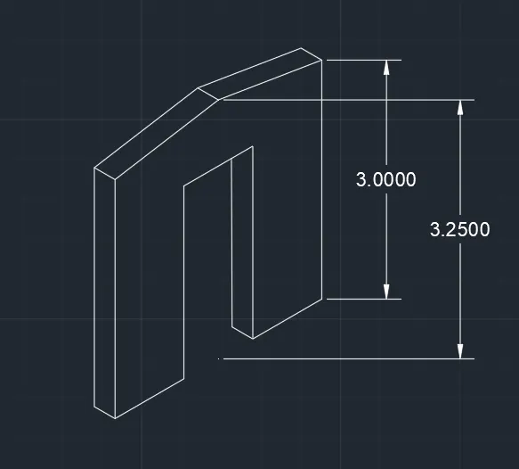
Creating a Floor plan, Footing detail and Isometric view using AutoCad
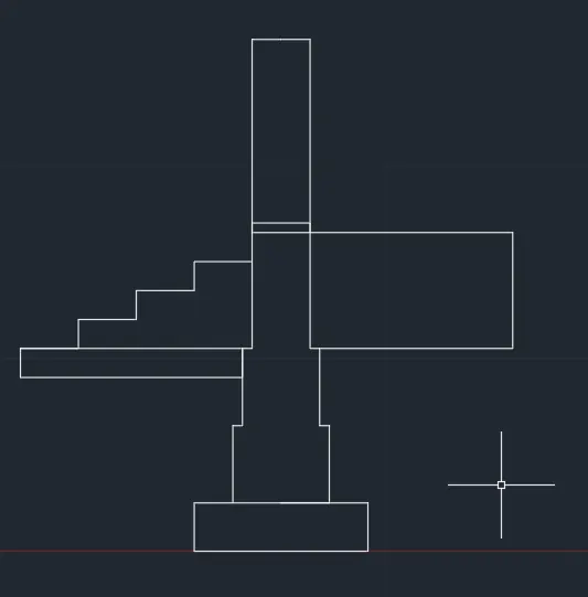
1. Aim:
To create a cross-section of load-bearing wall overspread footing using AutoCAD.
Procedure:
- Open AutoCAD.
- In the command prompt type RECTANG
- Specify first corner point 1,1
- Click on the dimensions
- Specify length of the rectangle 0.90
- Specify width of the rectangle 0.25
- In the command prompt type RECTANG
- Specify first comer point 1.2.1.25
- Click on the dimensions.
- Specify length of the rectangle 0.5
- Specify width of the rectangle 0.4
- In the command prompt type RECTANG
- Specify first corner point 1.25.1.65
- Click on the dimensions
- Specify the length of rectangle 0.4
- Specify width of rectangle 0.4
- In the command prompt type RECTANG
- Specify first corner point 1.3,2.05
- Click on the dimensions
- specify length of the rectangle 0.3
- specify width of the rectangle 0.6
- In the command prompt type RECTANG
- specify first corner point 1.3,2.65
- Click on the dimensions
- Specify length of the rectangle 0.3
- Specify width of the rectangle 0.05
- In the command prompt type RECTANG
- Specify first corner point 1.3,2.7
- Click on the dimensions
- Specify length of the rectangle 0.3
- Specify width of the rectangle 1
- In the command prompt type line specify point 1.3,2.05
- Specify the distance 1.15
- Specify the distance 0.15
- Specify the distance 1.15
- In the command prompt type line
- Specify point 0.15,2.05
- Specify the distance 0.3
- Specify the distance 0.15
- Specify the distance 0.3
- Specify the distance 0.15
- Specify the distance 0.3
- Specify the distance 0.15
- Specify the distance 0.3
Result:
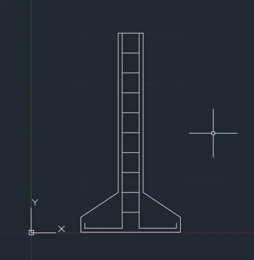
2. Aim: To create a cross-section of Isolated Footing.
Procedure:
- Open AutoCAD.
- In the command prompt type line
- Specify first point
- Specify the distance 0.15
- Specify the distance 0.25
- Specify the distance 0.38
- Join the line 1 and 2
- In the command prompt type line
- Specify first point 1.38,1.4
- Specify the distance 1.6
- Specify the distance 0.24
- Specify the distance 1.6
- Specify the distance 0.25
- Join line 1&2
- In the command prompt type line
- Specify first point 2,1.15
- Specify the distance 0.15
- In the command prompt type close
- In the command prompt type line
- Specify first point 1.04,1.08
- Specify the distance 0.04
- Specify the distance 0,38
- Specify the distance 1.96
- Specify the distance 1
- Specify the distance 1.96
- Specify the distance 0.38
- In the command prompt type offset
- Click on multiple
- Specify the distance of 0.2
Result:
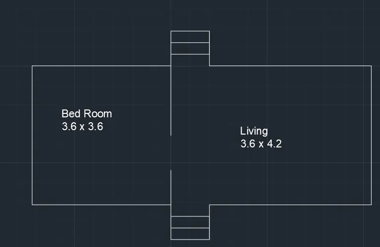
3. Aim:
To create the line diagram of Two-Bedroom Building
Procedure:
- In the command prompt type line
- Specify the first point 3,3
- Specify the distance 3.60
- Specify the distance 0.9
- Specify the distance 1
- Specify the distance 0.9
- Specify the distance 4.20
- Specify the distance 3.6
- Specify the distance 4.2
- Specify the distance 0.9
- Specify the distance 1
- Specify the distance 0.9
- Specify the distance 3.6
- Specify the distance 3.6
- In the command prompt type line
- Specify first point 6.6,3
- Specify the distance 0.9
- In the command prompt type line
- Specify first point 6.6,6.6
- Specify the distance 1.8
- In the command prompt type offset
- Specify the distance of 0.3 at steps
Result:
4)Aim:
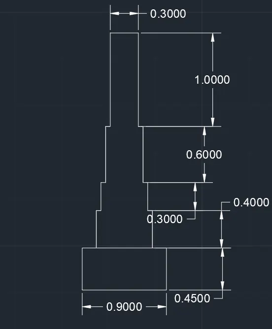
To create a cross-section of load-bearing wall showing foundation details
Procedure:
- Command: _rectang
- Select Dimensions
- Specify length for rectangles 0.9
- Specify width for rectangles 0.45
- Specify other corner point or [Area/Dimensions/Rotation]:
- Command: _rectang
- sELECT dIMENSIONS
- Specify length for rectangles 0.6
- Specify width for rectangles 0.4
- Specify other corner point or [Area/Dimensions/Rotation]:
- Point or option keyword required.
- Specify other corner point or [Area/Dimensions/Rotation]:
- Command: _rectang
- Specify first corner point or [Chamfer/Elevation/Fillet/Thickness/Width]:
- Select Dimensions
- Specify length for rectangles 5
- Specify width for rectangles 3
- Command: _rectang
- Specify first corner point
- Select Dimensions
- Specify length for rectangles 0.4
- Specify width for rectangles 0.6
Result:
5)Aim:
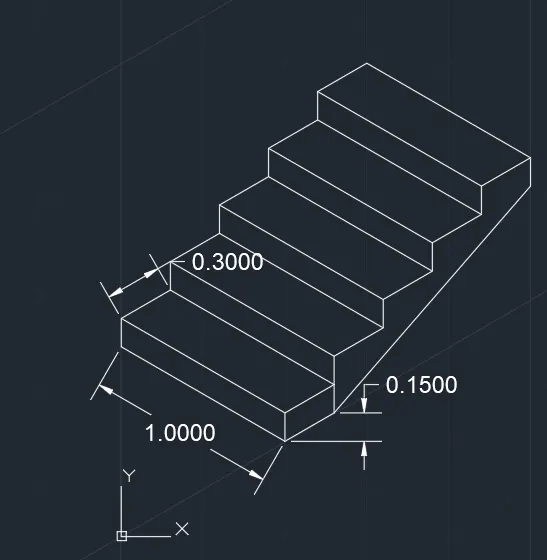
To create an Isometric view of steps.
Procedure:
- Type DS in command box
- Put snap Off and grid off. click isometric snap on.
- Switch on orthomode.
- Click isometric left in the status bar.
- Enter L in the command box.
- In the command box type line
- Enter first point 3,3.
- Place the cursor upwards and enter 0.15.
- Place the cursor right side and enter 1.00
- Place the cursor downside and enter 0.15
- Place the cursor left side and enter 1.00
- Enter L in the command box
- Enter 0.3 as the first point in command box.
- COpy line 0.3 in length.
- Enter line on command box 3.3
- In right side click and enter 0.15
- Join these two lines.
Result:
6. Aim:
To draw the isometric view of gable wall.
Procedure:
- Open AutoCad
- In the command prompt type ds.
- In drafting settings off snap and grid.
- Select on isometric snap.
- Switch ortho ON
- In the command prompt type line.
- Specify first point
- Draw line of length 1 toalong the right side
- Extend the line upwards to a length of 2.42
- Extend the line to a length of 1 to right side
- Extend the line to a length of 2.42 downwards
- Extend the line to a length of 1 to right side
- Extend the line towards upwards to a length of 3
- Connect the line horizontally with previous line.
- From the mid point entend the line to 0.25 upwards.
- Join the ends with the extentsion and delete the original line
- In the command prompt type Isoplane Left
- Draw 0.3 towards left side from every point
- Press f5 to get the line in the desired direction.
Result: