Week 1 Challenge
1. Truss type reasoning
Out of the two through type truss systems shown below, which is the most efficient in carrying gravity load? Reason it out.
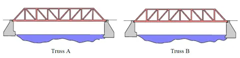
Aim: To describe which is the most efficient truss in carrying gravity load.
Truss A, also known as a Pratt Truss, is a popular design used for bridges with spans ranging from 10 to 30 meters. This truss design is known for its diagonal members, which are designed to withstand tension for gravity loads, while its vertical members are designed to withstand compression.
The Pratt Truss is a preferred choice for structures that experience significant gravity loads, such as roof structures and bridges. Moreover, it is renowned for its efficiency in terms of material usage, requiring less material than other truss designs, which makes it a cost-effective option for construction projects.
Truss B, also known as a Howe Truss, is a widely used design for light roofing, where the longer diagonal members are in compression. This truss experiences tension when the stresses reverse due to wind loads. It is the converse of the Pratt Truss and is commonly utilized for spans ranging from 10 to 30 meters.
The Howe Truss is particularly suited for structures that experience significant compression loads, making it an ideal option for light roofing. Moreover, it is known for its ability to handle tension loads caused by wind loads. It is the opposite of the Pratt Truss in terms of its diagonal member orientation, making it a suitable alternative for various construction projects.
Conclusion:
Truss A is most effiecient truss in carrying gravity load.
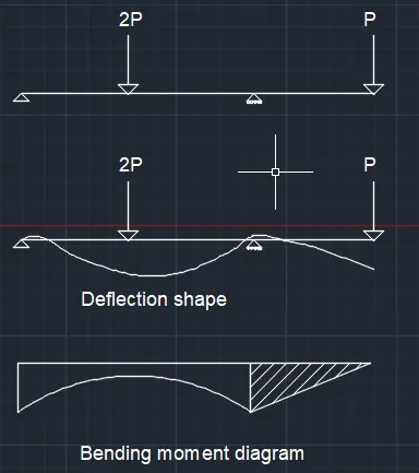
2. Deflection shape & Bending Moment Drawing (Qualitative approach)
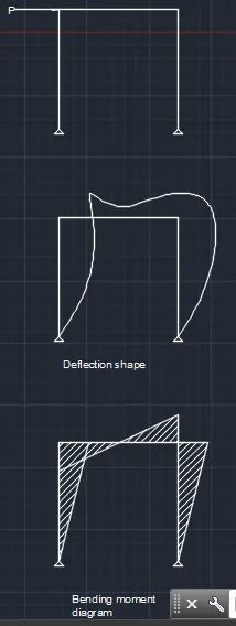
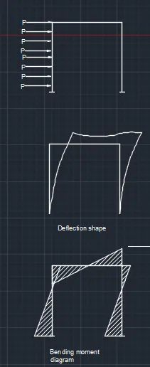
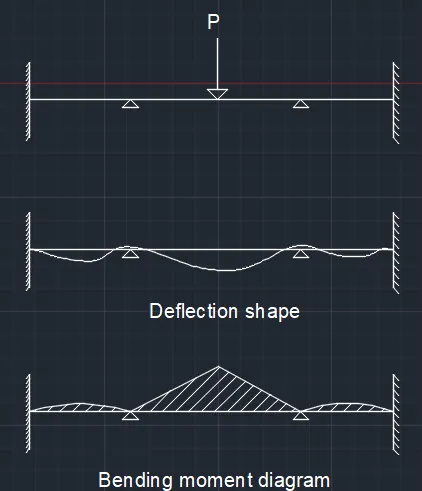
For the beam & Frame below draw deflected shape and bending moment drawing. (Qualitative approach). E & I are constants.
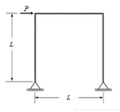
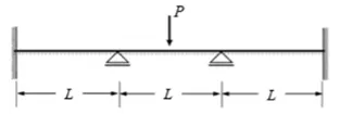
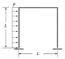
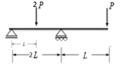
Aim: To draw Bending moment diagram and deflection shape of a given frame and sections.
3. Determine MOI, Weight, C/S area of sections below
Aim: To determine the weight and Moment of inertia of the given sections.
Moment of Inertia along X-Axis = Sum of Ixx of all members in a section.
Moment of Inertia along Y-Axis = Sum of Iyy of all members in a section.
Ixx of all member = bd3 /12 + A(d')2
where,
b is width of member
d is Depth of member
A is Area of member
d' is │Y - y│
y is centroidal axis in y direction of each member
Y' is centroidal axis in y direction of Whole member
Iyy of all member = db3 /12 +A(d')2
where,
b is width of member
d is Depth of member
A is Area of member
d' is │X - x│
x is centroidal axis in x direction of each member
X' is centroidal axis in x direction of Whole member
Weight of Section = Cross Sectionv area x Unit Weight of Steel
Where,
Unit Weight of Steel = 7850 kg/m3
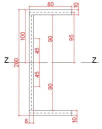
For C channel section
Let's calculate Centroidal axis in Y direction
Y'= 200/2=100 mm
Now let's calculate centroidal axis in X direction
X' = (a1x1+a2x2+a3x3)/(a1+a2+a3)
X'= (800x40+1440x8+800x40)/800+1440+800= 22.95 mm
Let's calculate Ixx
Ixx= Ixx1+Ixx2+Ixx3
Ixx1= (bd^3/12)+Ah1^2
= (80X10^3/12) + 800 X 95^2
= 72.27X10^6 mm^4
Ixx2= (8x180^3/12)+1440 = 38.89x10^6 mm^4
Ixx3= (80X10^3/12) + 800 X 95^2= 72.27x10^6 mm^4
Hence Ixx= (77.27+38.89+72.27)x 10^6 = 183.43x10^6 mm^4
Now let's calculate Iyy
Iyy= Iyy1+ Iyy2+ Iyy3
Iyy1= Iyy2= (db^3/12)+A1h1^2
= (80x10^3/12) + 800x(40-22.95)^2
= 0.66x10^6 mm^4
Iyy2= (180x8^3/12)+1440x(22.95-4)^2
= 0.52x10^6 mm^4
Iyy= ((0.66X2) + 0.52)x 10^6= 1.84x10^6 mm^4
Weight of the sections are =7850 x (0.0008+ 0.00144+0.0008)= 23.86Kg/m.
Let's calculate Centroidal axis in Y direction
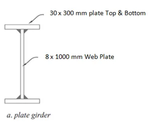
Y'= 300/2=150 mm
Now let's calculate centroidal axis in X direction
X' = 1060/2=530 mm
Let's calculate Ixx
Ixx= Ixx1+Ixx2+Ixx3
Ixx1=Ixx3= (bd^3/12)+Ah1^2
= (300X30^3/12) + 9000 X 515^2
= 2387.70^6 mm^4
Ixx2= (8x1000^3/12)= 666.67x10^6 mm^4
Hence Ixx= (2387.7+666.67+2387.7)x 10^6 = 5442.07x10^6 mm^4
Now let's calculate Iyy
Iyy= Iyy1+ Iyy2+ Iyy3
Iyy1= Iyy3= (db^3/12)+A1h1^2
= (30x300^3/12)
= 67.51x10^6 mm^4
Iyy2= (1000x8^3/12)
= 0.05x10^6 mm^4
Iyy= (67.51+67.51+0.05)x 10^6= 135.07x10^6 mm^4
Weight of the sections are =7850 x (0.009+ 0.009+0.008)= 204.1Kg/m.
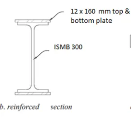
Let's calculate Centroidal axis in Y direction
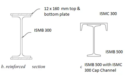
Y'= 324/2=162 mm
Now let's calculate centroidal axis in X direction
X' = 160/2=80 mm
Let's calculate Ixx
Ixx= Ixx1+Ixx2+Ixx3+Ixx4+Ixx5
Ixx1=Ixx5= (bd^3/12)+Ah1^2
= (160X12^3/12) + 1920 X 156^2
= 46.75x10^6 mm^4
Ixx2= Ixx4= (140x7.7^3/12)+146.15^2x1078= 23.03x10^6 mm^4
Ixx3= (8x284.6^3/12)= 15.37x10^6 mm^4
Hence Ixx= ((46.75x2)+(23.03x2)+15.37)x 10^6 = 154.93x10^6 mm^4
Now let's calculate Iyy
Iyy= Iyy1+ Iyy2+ Iyy3+Iyy4+Iyy5
Iyy1= Iyy5= (db^3/12)+A1h1^2
= (12x160^3/12)
= 4.10x10^6 mm^4
Iyy2= Iyy4=(140x7.7^3/12)
= 0.01x10^6 mm^4
Iyy3=(284.6x8^3/12)
= 0.01x10^6 mm^4
Iyy= ((4.10x2)+(0.01x3))x 10^6= 8.23x10^6 mm^4
Weight of the sections are =7850 x ((0.002x2)+( 0.001x2)+0.002)= 62.8 Kg/m.
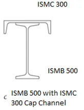
Let's calculate Centroidal axis in Y direction
Y'= (a1y1+a2y2+a3y3+a4y4+a5y5+a6y6)/(a1+a2+a3+a4+a5+a6)
=((2127.84x3.9)+(1224x45x2)+(3096x8.6x2)+(4749.12x232.80)/(2127.84+1224x2+3096x2+4749.12)
=82.32 mm
Now let's calculate centroidal axis in X direction
X' = 300/2=150 mm
Let's calculate Ixx
Ixx= Ixx1+Ixx2+Ixx3+Ixx4+Ixx5+Ixx6
Ixx1= (bd^3/12)+Ah1^2
= (272.80X7.8^3/12) + 2127.84 X 421.58^2
= 378.19x10^6 mm^4
Ixx2= Ixx3= (13.6x90^3/12)+1224x380.48^2= 178.02x10^6 mm^4
Ixx4= (180x17.2^3/12)+3096x409.08^2=518.11x10^6 mm^4
Ixx5= (10.2x465.60^3/12)+4749.12x167.68^2=219.55x10^6 mm^4
Ixx6= (180x17.2^3/12)+3096x82.32^2=21.06x10^6 mm^4
Hence Ixx= (378.19+178.02x2+518.11+219.55+21.06)x 10^6 = 1492.95x10^6 mm^4
Now let's calculate Iyy
Iyy= Iyy1+ Iyy2+ Iyy3+Iyy4+Iyy5+Iyy6
Iyy1= (db^3/12)+A1h1^2
= (7.8x272.80^3/12)
= 13.20x10^6 mm^4
Iyy2= Iyy3=(90x13.6^3/12)+1224x143.2^2
= 25.12x10^6 mm^4
Iyy4= Iyy6=(17.2x180^3/12)
= 8.36x10^6 mm^4
Iyy5=(465.60x10.2^3/12)
= 0.04x10^6 mm^4
Iyy= (13.20+25.12+25.12+8.36+8.36+.04)x 10^6= 80.2x10^6 mm^4
Weight of the sections are =7850 x (0.002+0.001+0.001+0.003+0.003+0.005)= 117.75 Kg/m.
4. Load calculation problem
For the floor framing below, Calculate the load on interior beam, Exterior beam, Interior Girder and exterior girder having Floor Load of 10kN/m2
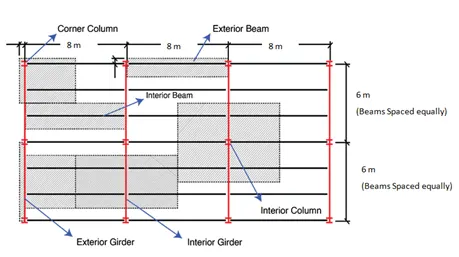
Aim: To calculate load of interior beam, exterior beam, interior girder and exterior girder.
We know that
Floor Load - 10kN/m2
Hence,
Tributary Width of Interior Beam = 1/2 x (2+2) = 2 m.
Tributary Width of Exterior Beam = 1/2 x (0+2) = 1 m.
Tributary Width of Interior Girder = 1/2 x (8+8) = 8 m.
Tributary Width of Exterior Girder = 1/2 x (0+8) = 4 m.
So,
Load on beam = Tributary width x floor load
Load on Interior Beam = 2 x 10 = 20 kN/m.
Load on Exterior Eeam = 1 x 10 = 10 kN/m.
Load on Interior Girder = 8 x 10 = 80 kN/m.
Load on Exterior Girder = 4 x 10 = 40 kN/m
5. Expansion joint size determination for temperature stated problem
Assuming a bridge, made of steel, with an initial total length of 2000 m at -20 ºC, calculate the length difference at 40 ºC and its total length.
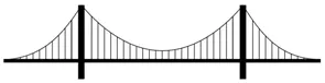
Coefficient of Thermal expansion of steel = 12x10-6/°C
Aim: To determine expansion joint size of a bridge when the temperature is 40 degree celcius.
Introduction: The size of the material at different temperature are measured to understand their property by which we will be able to provide proper expansion joint to the structure being built up to avoid any future consequences.
We know that the total length of the bridge at -20 degree celcius is 2000m and the expansion coeffiecient of the material is 12x10-6/°C.
To understand the total length of the bridge at 40 degree celcius is that we need to calculate differece in temperature they are
ΔT = 40–(−20)=60 degree celcius.
Hence the length difference is
=12x10-6 x 2000 x 60 = 1.44 m
So the total lent of the bridge at 40 degree celecius is
= 2000+1.44= 2001.44 m