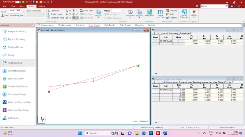
Week 1 Challenge
Question 1.1- Write the steps involved to upload a .std file through web mail?
Answer-
- Select STAAD Import from the backstage.
The Import from STAAD.Pro dialog opens.
- Click [...] in General settings to browse and select a STAAD.Pro (*.std) file to import.
- Select Use Mapping File in Section Mapping settings, and then click [...] to browse and select a mapping file to import.
Note: Mapping files are delivered with AECOsim Building Designer, and are named using analysis program names. Their function is to compare two lists of section data, and to map the STAAD.Pro sections to the corresponding sections in AECOsim Building Designer. They are located in the active configuration \\Configuration\Datasets\[active dataset]\Datadata folder
- Set the catalog type and catalog instance assignments for the imported member types. This data is used by AECOsim Building Designer to rebuild the members' structural data as defined in the structural member catalogs.
- In Steel settings, select a section definition that is to be designated as the Default Section Name. This section definition is applied to imported members whose section data is not available in AECOsim Building Designer.
- Check Verify to scan the imported file for unknown sections.
The Unknown Sections dialog appears providing an opportunity to write the unknown sections to the active XML section definition file before importing.
- In Revision Tracking, check Use Design History. Design History tracks changes to a DGN file. Viewing details about the revision by using the controls on this tool.
- Click Import.
The update design dialogue appears. Review detailed information about each imported member and select which ones you want to import before accepting them into the target DGN file.
Note: Update Design Results contains Load Case and Load Combination data imported from the STAAD.Pro (*.std) file. - Click Update to complete the import process.
The structure is updated.
Question 1.2- Name the different materials that can be designed using STAAD Pro.
Answer- STAAD Pro is a structural analysis and design software widely used in civil engineering and construction industry. The software can be used to design a wide range of materials and structures, including:
-
Concrete structures: STAAD Pro can design and analyze reinforced concrete (RC) structures such as buildings, bridges, retaining walls, and tanks.
-
Steel structures: It can also be used to design steel structures such as trusses, columns, and beams.
-
Timber structures: STAAD Pro has the capability to analyze and design timber structures such as bridges, buildings, and roofs.
-
Composite structures: The software can be used to design composite structures that combine different materials such as steel and concrete.
-
Masonry structures: STAAD Pro can analyze and design masonry structures such as arches, columns, and walls.
-
Foundation systems: The software can also be used to design foundation systems such as footings, pile caps, and mat foundations.
-
Seismic analysis: STAAD Pro has advanced capabilities to perform seismic analysis and design of structures subjected to earthquake loads.
Question 1.3- Is it possible to capture images in STAAD Pro? If yes how?
Answer- Yes, it is possible to capture images in STAAD Pro. Here are the steps to capture an image in STAAD Pro:
-
First, open the structure model you want to capture an image of in STAAD Pro.
-
Adjust the view and orientation of the model in the 3D view window to get the desired perspective.
-
Go to the File menu and select the Export option.
-
In the Export dialog box, select the desired format for the image (e.g., BMP, JPEG, PNG) from the dropdown menu.
-
Select the Save as type option as Image Files.
-
Browse to the location where you want to save the image file, and give a name to the file.
-
Click the Save button to save the image.
Alternatively, you can also use the Print Screen key on your keyboard to capture an image of the STAAD Pro screen. Once you have captured the image, you can use an image editing software such as Microsoft Paint or Adobe Photoshop to crop, resize, and enhance the image as needed.
Question 1.3- Name the three ways by which you can create a model.
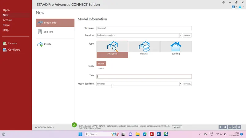
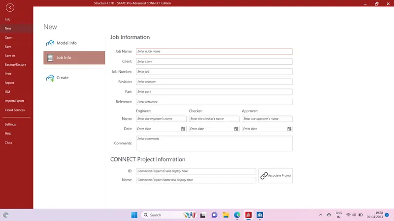
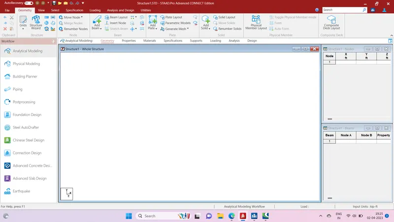
Answer- The three ways to create a model is as follows
1) Model Information
2) Job Information
3) Create option
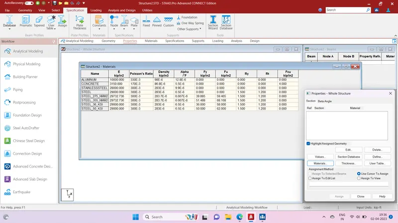
Question 1.5- Write the steps followed to assign properties in a model.
Answer-
-
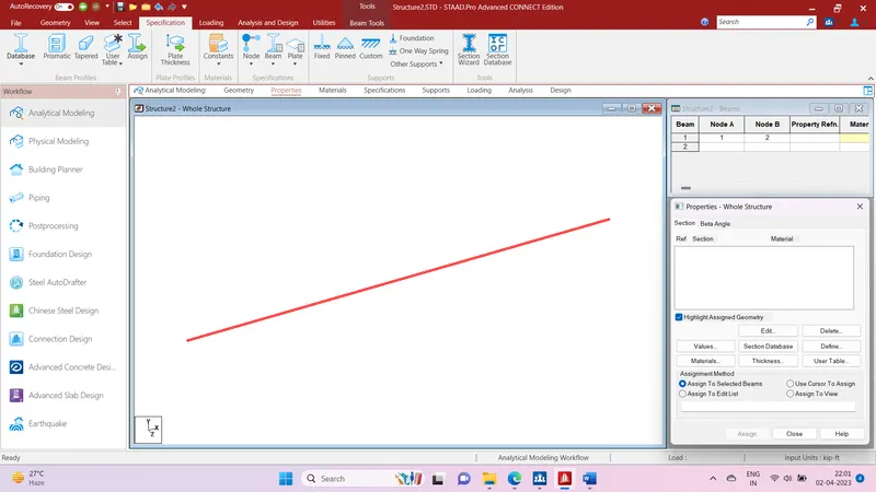
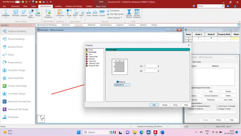
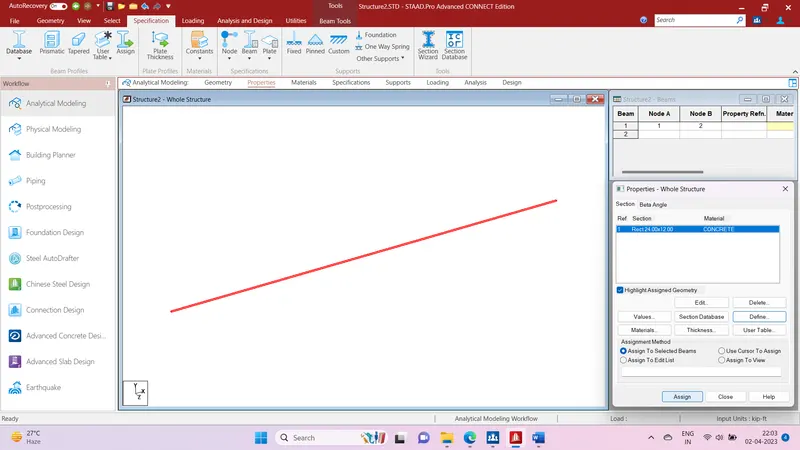
Select the "Properties" option from the toolbar in the STAAD.Pro GUI.
-
In the Properties dialog box, select the member(s) for which you want to assign properties.
-
Choose the appropriate property type from the list of options such as steel, concrete, timber, or aluminum.
-
Select the appropriate cross-section type from the list of available options for the chosen property type. For example, for a steel member, you may choose from options such as I-section, HSS section, angle section, etc.
-
Enter the values for the cross-sectional dimensions such as height, width, thickness, etc. depending on the chosen cross-section type.
-
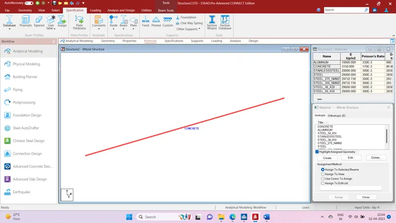
Enter other parameters such as material properties, shear area, moment of inertia, and torsional constant if required.
-
Click "OK" to assign the selected properties to the selected members.
Question 2.1- Name any six design parameter involved in RCC design.
Answer- Following are the six design parameter involved in RCC design
-
Concrete compressive strength: The compressive strength of concrete is a critical parameter in RCC design, as it determines the load-carrying capacity of the structure. The strength of concrete is typically expressed in megapascals (MPa).
-
Steel yield strength: The yield strength of steel is another important parameter in RCC design, as it determines the amount of stress that the steel reinforcement can withstand before it starts to deform. The yield strength of steel is typically expressed in megapascals (MPa).
-
Reinforcement ratio: The reinforcement ratio is the ratio of the cross-sectional area of steel reinforcement to the cross-sectional area of concrete. It is an important parameter in RCC design, as it influences the strength and stiffness of the structure.
-
Slab thickness: The thickness of a slab is an important design parameter, as it influences the load-carrying capacity, deflection, and cracking of the slab. The thickness of the slab is typically determined based on the design load and span.
-
Span-to-depth ratio: The span-to-depth ratio is the ratio of the span of a beam or slab to its effective depth. It is an important design parameter, as it influences the strength and deflection of the element.
-
Loadings: The loadings on a structure are an important design parameter, as they determine the design forces and moments that the structure must be able to resist. Loadings can include dead loads, live loads, wind loads, seismic loads, and other types of loads that may be applicable to the specific structure being designed.
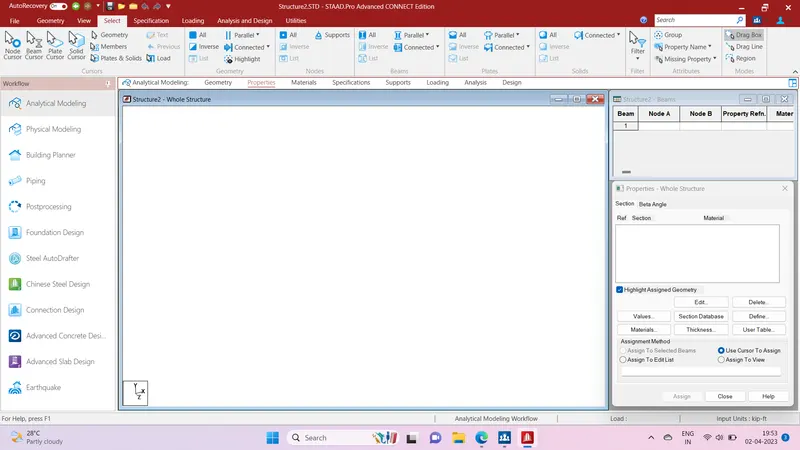
Question 2.2- What are the different cursor types available in STAAD Pro?
Answer- In STAAD.Pro, there are several cursor types available that can be used for different purposes. Here are the main cursor types:
-
Select cursor: This cursor is used to select and highlight elements in the STAAD.Pro model, such as nodes, members, and plates.
-
Zoom cursor: This cursor is used to zoom in and out of the model view.
-
Pan cursor: This cursor is used to move the model view up, down, left, or right.
-
Distance cursor: This cursor is used to measure the distance between two points in the model.
-
Angle cursor: This cursor is used to measure the angle between two lines or segments in the model.
-
Section cursor: This cursor is used to create cross-sections of members in the model for analysis and design purposes.
-
Axis cursor: This cursor is used to define the global and local coordinate systems for the model.
-
Offset cursor: This cursor is used to define offsets for members or nodes in the model.
-
Intersection cursor: This cursor is used to find the intersection point of two lines or segments in the model.
These cursor types can be accessed from the toolbar at the top of the STAAD.Pro interface, or by using shortcut keys on the keyboard. The selection of the appropriate cursor type depends on the task at hand and can help to streamline the modeling and analysis process in STAAD.Pro.
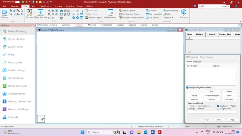
Question 2.3- How will you generate different views for a model? State the steps involved.
Answer- Following are the steps to generate different views for a model in STAAD.Pro:
-
Open the STAAD.Pro model for which you want to generate different views.
-
Select the "View" option from the toolbar at the top of the screen.
-
Choose the type of view you want to generate from the list of available options, such as plan view, elevation view, 3D view, or perspective view.
-
If necessary, adjust the settings for the view, such as the scale or rotation angle.
-
Click "OK" to generate the selected view.
-
Repeat the above steps to generate additional views as needed.
-
To switch between different views, select the "View" option again and choose the desired view from the list of available options.
-
You can also customize the appearance of the views by selecting the "View Settings" option from the toolbar and adjusting the settings such as the background color, line styles, and element colors.
Question 2.4- Explain the procedure to define a “Simply Supported” condition in STAAD Pro
Answer- To define a "Simply Supported" condition in STAAD.Pro, you can follow these steps:
-
Open the STAAD.Pro model for which you want to define the "Simply Supported" condition.
-
Select the member for which you want to define the condition. You can do this by clicking on the member in the model view, or by selecting it from the structure tree on the left-hand side of the interface.
-
Right-click on the selected member and choose "Properties" from the context menu.
-
In the "Member Properties" dialog box, select the "Releases" tab.
-
Check the box next to "Fixed (F)" under the "End Releases" section. This will remove all the fixities from the selected end of the member.
-
Check the box next to "Shear (V)" under the "End Releases" section. This will release the member for shear forces.
-
Check the box next to "Moment (M)" under the "End Releases" section. This will release the member for bending moments.
-
Click "OK" to save the changes and close the dialog box.
-
Repeat the above steps for all the other members in the model that you want to define as "Simply Supported."
Question 2.5- Name any five topics that you will include while creating DBR.
Answer- DBR stands for Design Basis Report, which is a document that outlines the design criteria, assumptions, and constraints for a particular engineering project. The topics that may be included in a DBR can vary depending on the type of project and the specific requirements of the client, but here are five topics that could be covered:
-
Project overview: This section provides an overview of the project, including its purpose, scope, and goals. It may also include information on the project site, the client's requirements, and any relevant regulations or standards that need to be followed.
-
Design criteria: This section outlines the design criteria that will be used to develop the engineering design, such as the load requirements, the design codes and standards that will be followed, and any other specifications that need to be met.
-
Assumptions and limitations: This section lists any assumptions that have been made during the design process, as well as any limitations or constraints that may impact the design. This can help ensure that the design is realistic and achievable within the given constraints.
-
Design methodology: This section describes the design methodology that will be used to develop the engineering design, including any analysis techniques or software tools that will be used. It may also include information on the design process, such as the steps involved in developing the design and the roles and responsibilities of the design team.
-
Quality control and assurance: This section outlines the quality control and assurance measures that will be put in place to ensure that the design meets the specified criteria and standards. It may include details on the testing and inspection procedures that will be used, as well as any documentation requirements or record-keeping procedures.
Question 2.6- Describe the term “Multi material design” of STAAD Pro.
Answer- The term "Multi-material design" of STAAD Pro defines the structure that is designed by implementing more than one structural material. For example, suppose I am designing an R.C.C. building but at the same time few parts of that RCC building are composed of different materials like Steel in order to make the sheds, garage, etc. So This type of building design with different materials is known as the "Multi-Material Design".
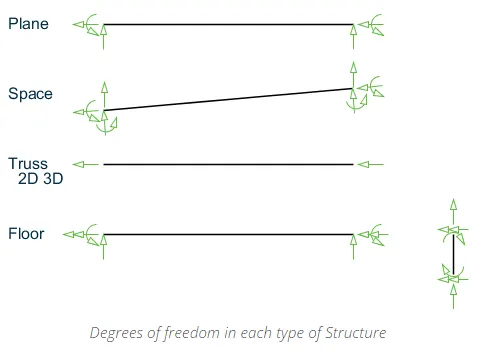
Question 3.1- Name the structure systems in STAAD Pro? Explain each system?
Answer-
-
Truss System: This system is used to model structures that consist of triangular trusses. A truss is a structure that consists of a series of interconnected triangles that form a stable structure. The truss system in STAAD Pro is used to analyze the stresses and strains in the truss members and to determine the forces acting on the members.
-
Beam System: The beam system is used to model structures that consist of beams. Beams are long, horizontal structural members that are used to support loads. The beam system in STAAD Pro is used to analyze the stresses and strains in the beams and to determine the deflection of the beams under load.
-
Column System: The column system is used to model structures that consist of vertical columns. Columns are used to support the weight of the structure and to transfer the loads to the foundation. The column system in STAAD Pro is used to analyze the stresses and strains in the columns and to determine the deflection of the columns under load.
-
Frame System: The frame system is used to model structures that consist of a combination of beams and columns. Frames are used to support loads and to transfer the loads to the foundation. The frame system in STAAD Pro is used to analyze the stresses and strains in the beams and columns and to determine the deflection of the structure under load.
-
Shell System: The shell system is used to model structures that have a thin, curved surface. Examples of structures that can be modeled using the shell system include domes, tanks, and shells. The shell system in STAAD Pro is used to analyze the stresses and strains in the shell and to determine the deflection of the shell under load.
-
Plane System: The plate system is used to model structures that have a flat surface. Examples of structures that can be modeled using the plate system include slabs, walls, and foundations. The plate system in STAAD Pro is used to analyze the stresses and strains in the plates and to determine the deflection of the plates under load.
Question 3.2- Explain the coordinate system adopted in STAAD Pro software.
Answer-
The coordinate system that is adopted in STAAD Pro software are X, Y, and Z coordinates.
- So basically the co-ordinate system adopted in STAAD Pro software is:
- Global Axis: Mainly global axis is fixed in the coordinate system.
- Local Axis: Local axis is variable in nature. We can change the local axis but not the global axis.
As the STAAD Pro software. Basically, it uses a conventional cartesian coordinate system, and in this system Y is a global axis that is in an upward direction. We can say that the height of the building is always parallel to the global Y-axis
Question 3.3- Elaborate DBR and its uses.
Answer-
DBR stands for Design Basis Report. It is a document that outlines the design criteria and assumptions that are used in the design of a particular structure or project. The DBR provides a systematic and structured approach to the design process, helping to ensure that the design meets all the necessary requirements and is safe, reliable, and efficient.
The DBR typically includes the following information:
-
Design Loads: The DBR specifies the design loads that the structure must be able to withstand. This includes the weight of the structure itself, as well as any additional loads from wind, earthquakes, snow, or other environmental factors.
-
Material Properties: The DBR specifies the material properties that will be used in the design of the structure. This includes the strength, stiffness, and other physical properties of the materials.
-
Design Standards: The DBR specifies the design standards that will be used in the design of the structure. This includes industry-specific standards, such as those set by the American Institute of Steel Construction (AISC) or the American Concrete Institute (ACI).
-
Analysis Methods: The DBR specifies the analysis methods that will be used to evaluate the structure's performance under different load conditions. This includes the use of software programs like STAAD Pro, SAP2000, or ETABS, as well as manual calculations and other analysis methods.
-
Design Assumptions: The DBR specifies the design assumptions that are made during the design process. This includes assumptions about the behavior of the materials, the load distribution, and the structural response.
The DBR is a critical document in the design process, as it provides a foundation for all subsequent design decisions. It is also used as a reference document throughout the project, helping to ensure that the design stays on track and meets all the necessary requirements. In addition, the DBR is often required by regulatory agencies and clients as part of the project approval process.
Question 3.4- Explain the different types of analysis options in STAAD pro.
Answer-
The main types of analysis options in STAAD Pro are as follows:
-
Static Analysis: Static analysis is the most common type of analysis used in structural engineering. It evaluates the behavior of a structure under static loading conditions, such as dead loads, live loads, and wind loads. In STAAD Pro, static analysis can be performed using linear or nonlinear methods.
-
Dynamic Analysis: Dynamic analysis is used to evaluate the behavior of a structure under dynamic loading conditions, such as seismic loads or wind loads with vortex shedding. In STAAD Pro, dynamic analysis can be performed using time history analysis, response spectrum analysis, or modal analysis.
-
Buckling Analysis: Buckling analysis is used to evaluate the behavior of slender structures under compressive loading conditions. In STAAD Pro, buckling analysis can be performed using linear or nonlinear methods.
-
Pushover Analysis: Pushover analysis is used to evaluate the behavior of a structure under lateral loading conditions, such as earthquake loads. In STAAD Pro, pushover analysis can be performed using static or dynamic methods.
-
Nonlinear Analysis: Nonlinear analysis is used to evaluate the behavior of a structure when the material behavior or geometric nonlinearity is significant. In STAAD Pro, nonlinear analysis can be performed using the finite element method or the equivalent frame method.
-
P-Delta Analysis: P-Delta analysis is used to evaluate the effect of second-order or geometric effects on the behavior of a structure. In STAAD Pro, P-Delta analysis can be performed using linear or nonlinear methods.
Question 3.5- Explain the difference between Fixed and Fixed But condition.
Answer-
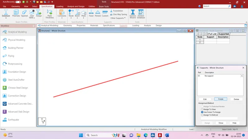
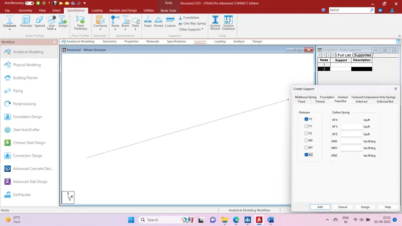
In STAAD Pro, "Fixed" and "Fixed But" are boundary conditions that are used to model the supports of a structure. The main difference between these two boundary conditions is that a "Fixed" support restrains the translation and rotation of the node in all three directions, while a "Fixed But" support restrains the translation of the node in all three directions, but allows rotation.
More specifically, when a node is assigned a "Fixed" boundary condition, it is assumed that the node is rigidly connected to the supporting structure and cannot move or rotate in any direction. This means that the node is fully restrained in all six degrees of freedom: three translations (X, Y, Z) and three rotations (about X, Y, Z).
On the other hand, when a node is assigned a "Fixed But" boundary condition, it is assumed that the node is connected to the supporting structure by a hinge or a pin, which allows rotation about one or more axes. This means that the node is restrained in all three translations (X, Y, Z) but is allowed to rotate about one or more of the axes.
The main advantage of using a "Fixed But" boundary condition is that it allows for more realistic modeling of the support conditions of a structure. In some cases, such as when modeling a beam-to-column connection or a joint, it may be necessary to allow for rotational movement at the support. The use of "Fixed But" boundary conditions allows for this rotational movement while still providing restraint in the translational directions.
In summary, "Fixed" boundary conditions fully restrain a node in all six degrees of freedom, while "Fixed But" boundary conditions restrain a node in all three translations but allow rotation about one or more axes.